To Model a RC residential structure using TSD
1.
AIM: Setup model for RC building design and based on following parameters for cover
|
MEMBERS |
IN CONTACT WITH GROUND |
ABOVE GROUND |
|
Column |
50mm |
40mm |
|
Beam |
30mm |
25mm |
|
Slab |
30mm |
25mm |
|
Pilecap |
75mm |
|
|
Foundation |
50mm |
PROCEDURE:
- Open Tekla structural design
- Go to settings->Structure defaults
- Select the SSL for the cover in contact with the ground
- enter the cover values as given in the above table.
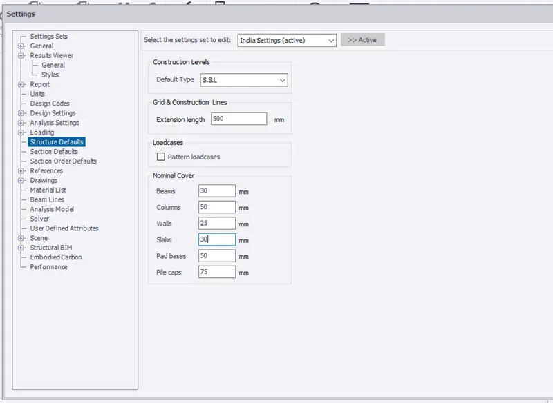
- For the cover above the ground change default type to TOF
- and apply the cover to the slabs
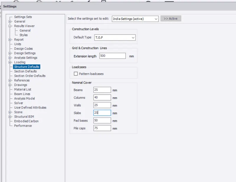
RESULT: The cover has been provided to the concrete materials
2.
AIM: Model grids as per the attachment 2,2.1 and 2.2
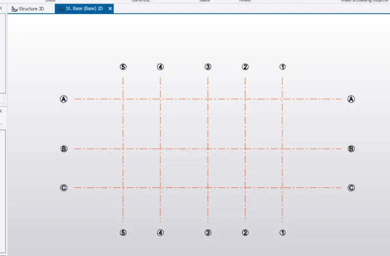
PROCEDURE:Gridlines are used to locate the columns and beams position in a structure.Gridlines are important as they help in placing the elemenst with accuracy
- on the previous question we were working
- Go to model tab->under grids and construction lines
- Draw grid lines accoring to the placement of the columns
- Click on Grids ->draw the grid line and then select parelled quick in grids panel
- Enter the distance of the grids as per the placing of the columns
- Then use the perpendicular grid and select the line to which u want the perpendicular grids
3.
AIM: Study the layout and write a summary for general arrangement of the structure
ANSWER:Before starting the design of any structure ,we need to study the layout and decide whether the layout is poosible according the structure behaviours. We also need to check that the columns placement is done at the place where it does not interfere with the passage or windows/doors.
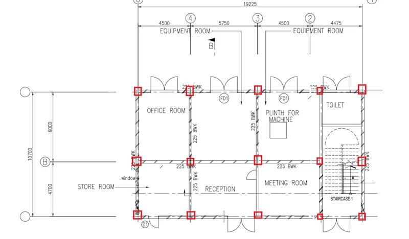
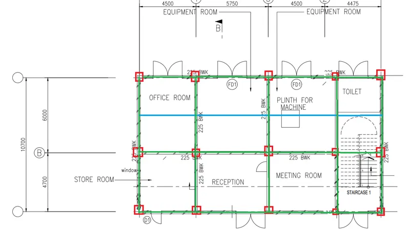
- Below shown is the column arrangement according to the plan
- as you notice one column line is not at the grid line 2
- we need to adjust the arrangement according to the entrance.
- The blue line shows the secondary beams
- Secondary beams are provided when the distance between 2 beams are high
- To reduce the deflection of the beams we provide secondary beams
- and we dsign the primary beams for torsion which support the secondary beam.
- the greem line show the primary beams
4.
AIM: Model RC columns, beams and slabs as per your general arrangement.
PROCEDURE:
- Go to model panel
- Constructution level->enter the details of the levels you want
- we have G+1 floor level in this plan
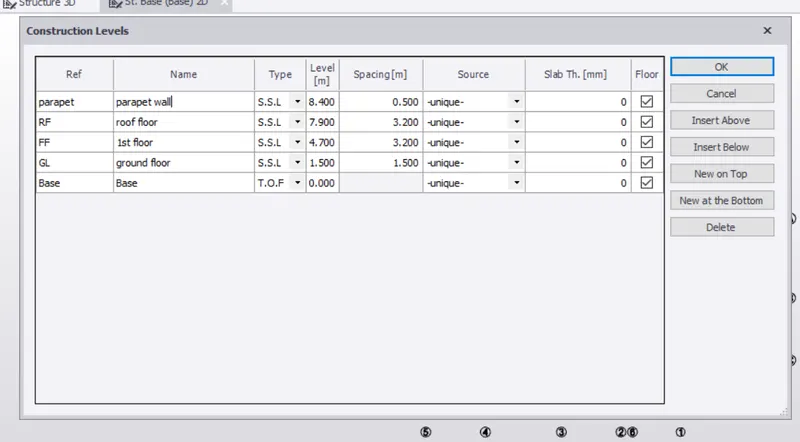
- After entering the detail->Click OK
- Now the construction level is given,
- Go to the base level
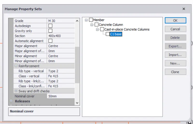
- Go to Home->manage property sets->New
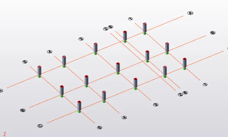
- Concrete columns->select the materials(M30,Fe415 Nominal cover=50mm)
- Now provide the columns at eh intersecton of the grids
- Go to model tab->select column C1->Select top level ground floor
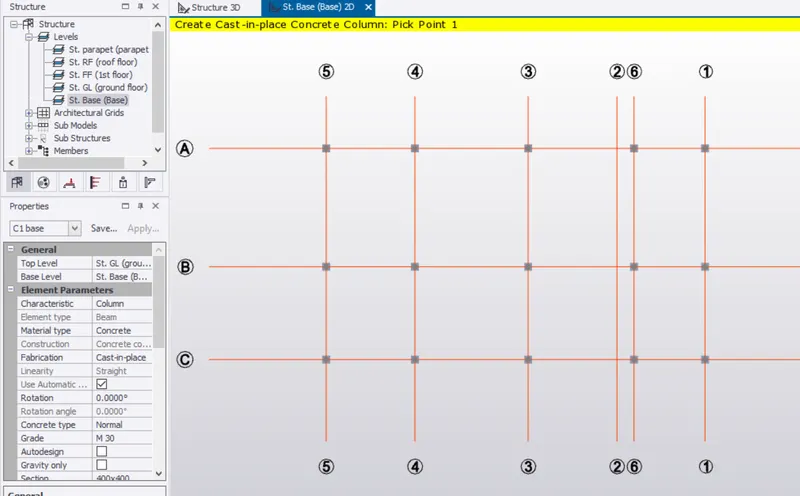
- Select 3D toggle to view in 3D
- Now we will add Beams to the plan
- Go to the attachment we got->Place the beams as per requirement
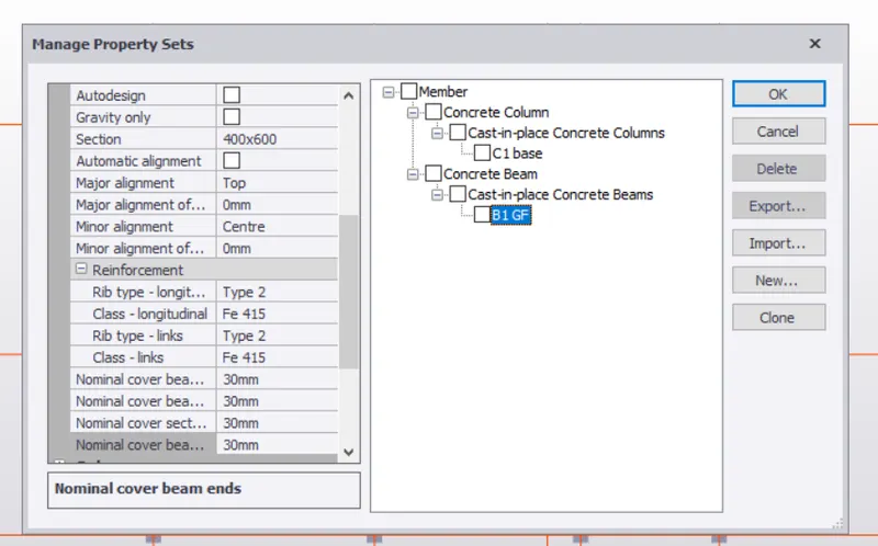
- Home->Manage property sets->New->Concrete beam
- Provide section 400x600,cover =30mm
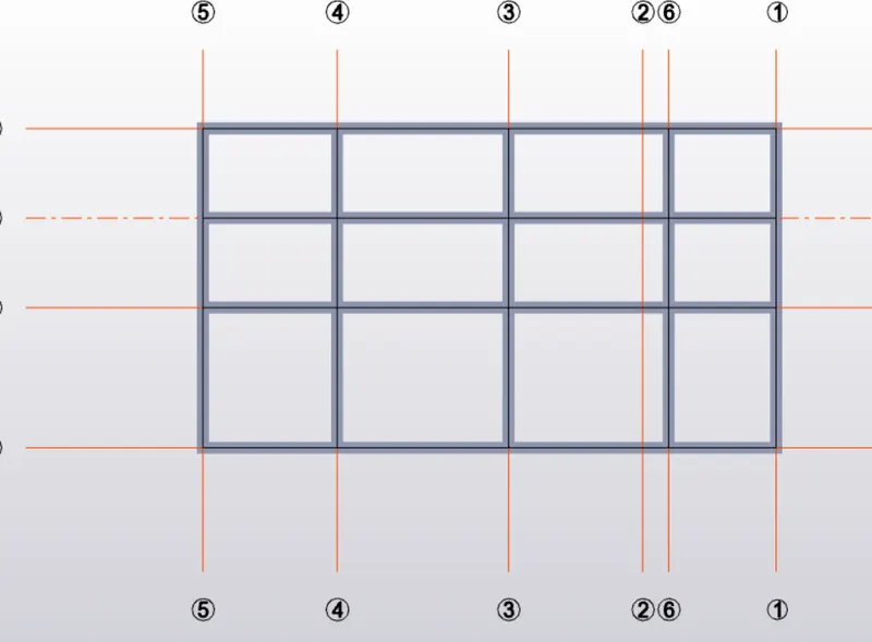
- Now place the beams over the columns
- Open the ground florr level
- Go to model->Concrete beam->select B1 and apply
- Go to 3D toggle
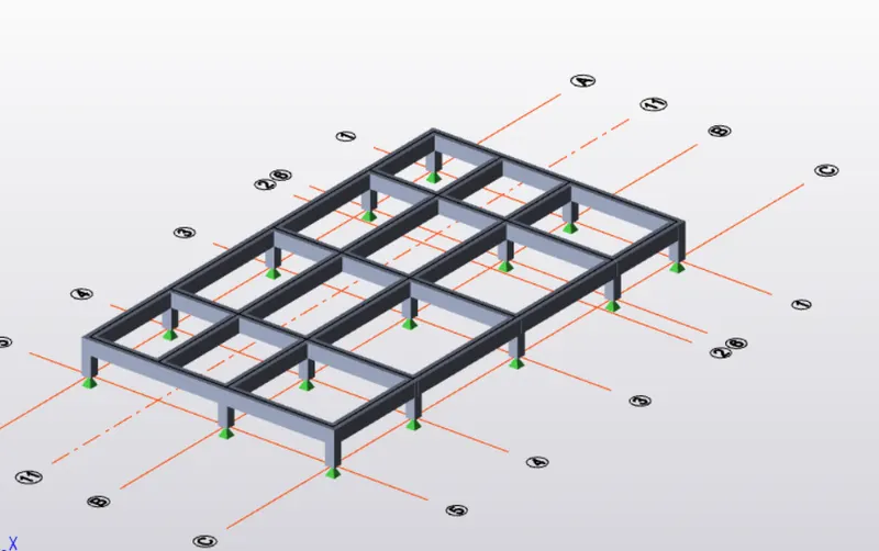
- Now we provide column upto the top with different cover
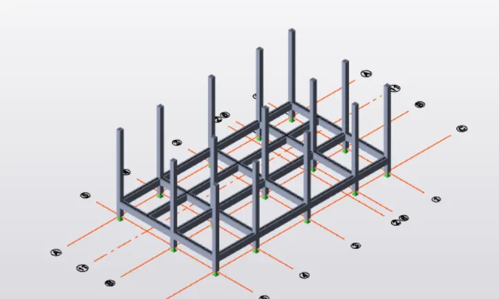
- After providing the column and beams to the structure
- 3D toggle view
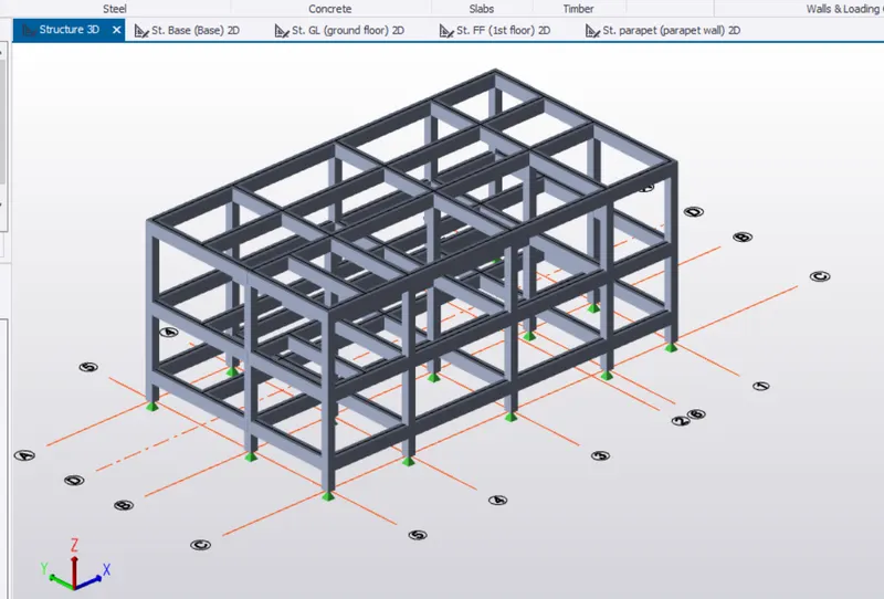
- Now we design the slabs for the structures
- Go to home panel->Manage property sets
- New slab on beams items
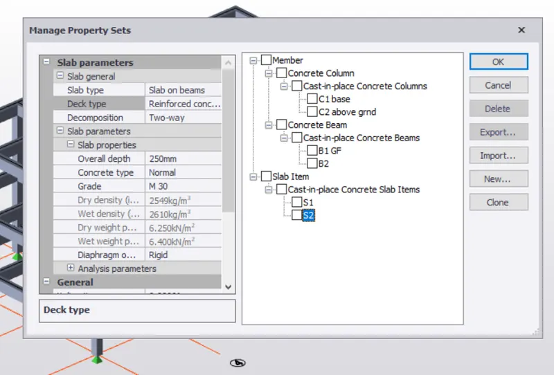
- Go to ground floor->Select slab on beams select the area where you want to place the beams
- Leave the area of slabs for the stairs
- we use slabs of lesser thickness(200mm) on the roof because live load will be less(if roof is not accessible)
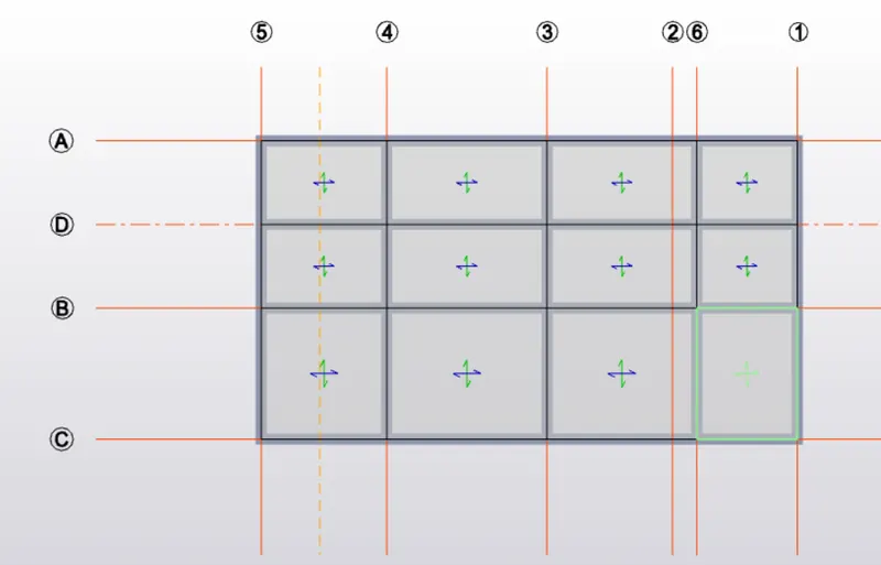
- Go to model panel->click on validate->no error shown
- go to structure 3D to view the model in 3D
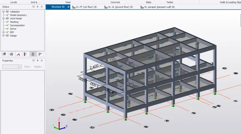
RESULT:
- concrete columns are placed
- concrete beams are placed
- slab on beams are placed
- model is validated and checked for errors.