Project 1 _Creating an Architectural plan for the provided plot size and develop relevant basic structural drawings
1.
AIM: Create an architectural plan of 60ft*20ft house plan .keeping the orientation EAST Draw the Elevation ,section of the plan.For the structural part draw the beam,column footing plan.
PROCEDURE:
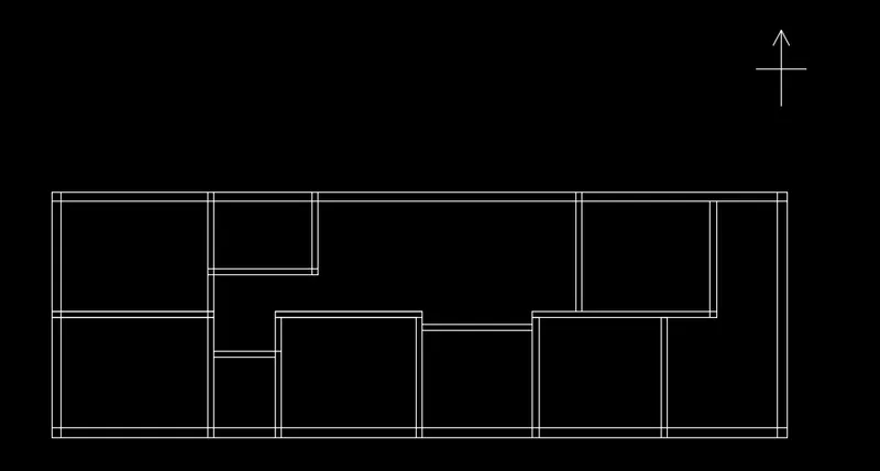
- To Draw the floor plan of the house (60ft x 20ft) by taking the width of the exterior wall as 9" and inner walls as 6"
- To draw the elevation of the house plan and taking the ceiling depth as 1'.
- Cutting the section as AA' for the section view.
- Taking placement of the coulm in the floor to make the column plan.
- Creating the plan of Beam line running throughout the walls of the house.
MAKING FLOOR PLAN
STEP1
Command:XLINE
- Draw a vertical and horizontal line for the house plan.
Command :OFFSET
- Take an offset of 60ft of vertical XLINE and 20ft offset of horizontal line as the house plan boundary.
Command :TRIM
- Trim the extra lines outside the house plan.
STEP2
Command:OFFSET
- Take offset of 9" to make the exterior wall. //From all the side towards inside
- Starting from the down left side,Take offset of 9' from horizontal line and 12' from vertical line //for the BEDROOM 3 &2
- Take 6" offset for interior wall.
Command:TRIM
- Trim the extra lines of the bedroom
Command:OFFSET
- TAke offset from vertical line of 6" for interior wall.
- Take offset of 8' and 5'6" from vertical and horizontal wall respectively. //For common TOILET size
- Take offset of 5' and 5'6" from vertical and horizontal wall respectively. //For attached toilet
- Take offset of 6".
STEP3
Command:TRIM
- Trim all the xtra edges of the walls.
Command:OFFSET
- Take offset of 21' and 9' from vertical and horizontal line from the toilet wall. //For the drawing and dining hall
- Take offset of 6" for interior wall.
- Now take offset of 11' and 9' from the vertical and hosrizontal line respectively. //For BEDROOM1
- Take offset of 6".
//Again use the trim command after making of each room/HAll.
Command:OFFSET
- Take offset of 9' &8'4" from vertical and horizontal walls. //For making kitchen
- Taking 6" offset for the walls.
//Like wise make the study room and living room from the above used methods.
STEP4
Command:TRIM
- Trim all the xtra edges of the walls.
RESULT:
STEP5
Command:RECTANGLE //To make the door
- make a rectangle of 2"x9"
Command:LINE
- Make a line of length 3' from the center of the rectangle.
Command:MIRROR
- Select the rectangle.
- choose the center of line a axis and make the mirror of rectangle
Command:LINE
- Make an horizontal line of 1" from the rectangle and then vertically upwards.
Command:CIRCLE
- From the pivot poin of the door draw a circle till the radius meets the other rectangle //To make the width of door panel
Command:TRIM
- Trim the extra circumference of the circle other than the door panel swing.
STEP6
Command :RECTANGLE //To make the windows
- make arectangle of 4'x9"
Command: OFFSET
- TAke an offset of 3"
- Connect the lines to the edges of the rectangle
STEP7
Command:COPY
- Copy the doors and windows to the rooms walls and entrance.
Command:TRIM
- Trim the lines doors panels
STEP8
Command:LAYER
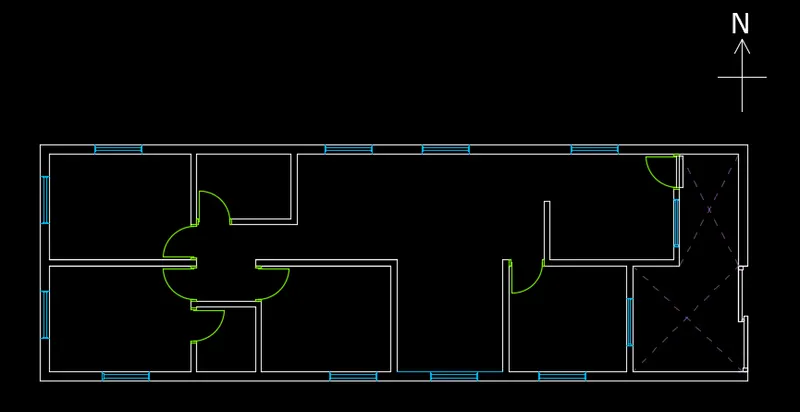
- Create a new layer of DOORS,WINDOWS,TEXT,VENT,SECTION LINES,CENTER LINES
- Select different colors for the different layers
//SELECT THE RESPECTIVE NAME LAYER WHEN WORKING ON THAT
- Select the doors and go to layers and select the layers to giver the corresponding properties //Similarly do it witht the vents
RESULT:
STEP8
Command :LAYER
- Select the dimension layer.
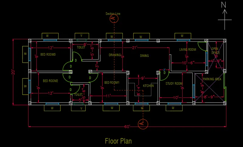
- select starting point and end point to show the dimensions. //To give the dimsion to the rooms
- "DIMSTYLE" ,to change the text style and size to the visible size. //To change ,create or modify the dimesion according to the need
Command: DIMCONTINUE
- To continue the dimesion along the path .
Command :TEXT
- Use single line text to write down the text on the plan .
- click on the area,specify the angle u need the text to be shown and type the text.
//USing the above command write the texts and dimension to the plan.
RESULT:
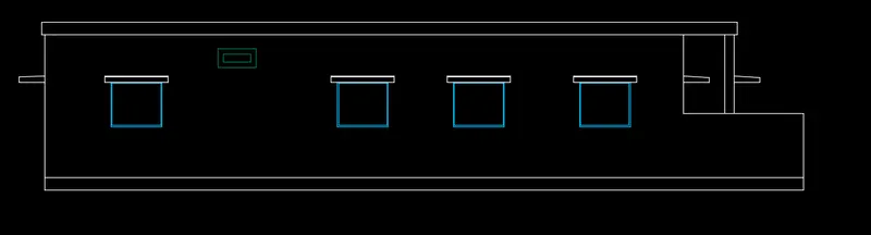
HOUSE ELEVATION
STEP9
Command:XLINE
- Extend and infinite line from the left and right side of the house plan below
- Draw a horizontal line for the ground floor.
command:OFFSET
- Take an offset of 13'3" from the ground level and to the top. //For total height of the elevation
- take 1' offset from top ceiling and ground level. //For ceiling and ground floor depth
Command:XLINE
- Extend and infinite line from the windows and vents of the plan to the elevation //For reference line
- draw a horizontal line at a height at the height of 4' from the start of the floor //For the height of the windows
STEP10
command:OFFSET
- Take offset of 5' from the floor level above for thr bouundary wall. //For the boundary wall of the house
Command:TRIM
- Trim the extra extruding line for the corner of the boundary wall
RESULT:
STEP11
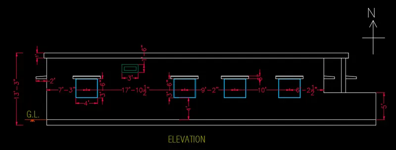
Command:RECTANGLE
- Create a rectangle of width 4'x3' from the intersection point of the XLINE we created. //For the sizeof window
- Create a rectangle above the window of size 5'x6". //Creating slab for chhajja
COmmand:COPY
- Copy the window, chhajja and paste it in the side for other windows at the same elevation using polar tracking.
Command:LINE
- Make a line of 9" horizontal n the left wall and OFFSET it at a distance of 6". //For the side view of the chhajja
- From the level of lower side of chhajja,extend a line of 2' horizontal and 3" vertical.
- Now join the line .
STEP12
Command:TEXT
- Make the text layer as current layer.
- Use single line text to write down the text on the plan .
- click on the area,specify the angle u need the text to be shown and type the text.
Command:DIMLINEAR
- Selcet the dimensions layer.
- Select the point on the windows and vents and height of the elevation //To give dimensions to the elevations
Command:DIMCONTINUE
- It will start taking dimension continously from the last position
RESULT:
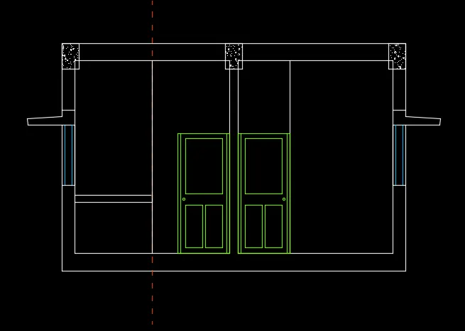
SECTION A-A'
STEP13
Command:XLINE
- MAke a horizontal line from top and bottob side of the house plan. //As a reference of the width of house
Command:ROTATE
- Rotate the elevation 90degree right and extend the height refernce line from the elevation.
Command:TRIM
- TRIM the extra line of the xline . //to make the section visible clearly.
STEP14
Command:OFFSET
- TAke an offset of 1' from the top ceiling and ground level
- Take offset as a height of 3' from the ground as kitchen slab.
Command :RECTANGLE
- Make a rectangle of 3'x7' and some smaller size door panel design //For the door
Command:CIRCLE
- Make a small circle for the door knob
STEP15
Command :RECTANGLE
- Make a rectangle 9"x3' for the window For making the section of windows
- TAke offset for the 3" from both the sides and join the edges
//Take reference for the height of chhajja from the ground level (from the elvation)
Command:OFFSET
- Take offset from the base of the chhajja to the upward direction of 6"
- Join the upper base of chhaja to the lower side of it
Command:TRIM
- TRIM the inside line of the chhajja
STEP16
Command:LAYER
- Select the "section line" layer and draw the section change plan line on it //To show the section plane change
- select the doors and windows layer and apply it to the doors and windows of the section plane.
RESULT:
STEP17
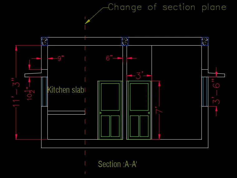
Command:TEXT
- Make the text layer as current layer.
- Use single line text to write down the text on the plan .
- click on the area,specify the angle u need the text to be shown and type the text.
Command:DIMLINEAR
- Selcet the dimensions layer.
- Select the point on the windows height,chhajja and doors
RESULT:
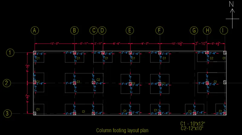
COLUMN FOOTING LAYOUT PLAN
STEP18
Command:COPY
- Copy all the columns from the plan of house.
- select a base point and paste it
Command:RECTANGLE
- make a rectangle boundary from top left corner to down right corner //To make an outer boundary for the footings
STEP19
Command:LAYER
- Select the "center line" .
Comand:LINE
- Draw a line from the center of the columns. //Keep a single line for the columns that are in same line
- Draw lines both vertically and horizontally direction of columns. //To make the grid position of the columns
Command:OFFSET
- Select the column and make an offset of 2'6" of each column //To make the footing size of the column
Command:TRIM
- Trim the outer portion of the column which are outside the boundary
Command:EXTEND
- Extend the center lines of columns to about 7' outside the boundary //Extension for the number of columns
STEP20
Command:CIRCLE
- Create a circle at the end of the center lines
Command:TEXT
- Got to TEXT layer
- Enter the text A,B,C,D.... in the vertical centre lines and 1,2,3 in horizontal //For perfectly identifying the individual column
- Write the topic of the drawing and column size.
- C1=9"x12" & C2=12"x9"
Command:DIMLINEAR
- Select the "dimensions" layer and make it current.
- select the point from center to center of the column
- enter "DIMCONTINUE" to continue the dimension //Select from center to center of the columns
RESULT:
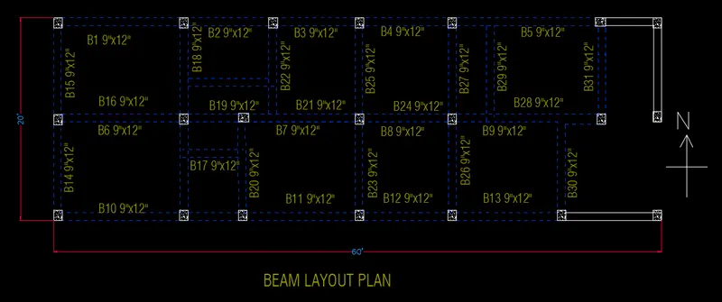
BEAM LAYOUT PLAN
STEP21
Commmand:COPY
- select all the walls of the plan and column //To take the exact position of walls
- select a base point an paste it .
Command:OFFSET
- Offset all the beams width to 9" (including inside walls) //as the width of plan of beam is 9"x12"
- The beam which are not connected to the column are hidden beams //Hidden beams are hidden inside the slab.
STEP22
Command:LAYER
- Selet the "beam" layer,make it as current.
- select one beam and make it the current layer. //It will make the beam into the beam layer
Command:MATCHPROP
- select the source object //The actual beam layer object
- select the destination object. //It will copy the properties of the source objet to destination object.
STEP23
Command:LTSCALE
- Enter a value to make the dashed lines visible accordingly.
Command:TEXT
- Change the layer to TEXT , and select a point on the beam plan(0 degrees).
- Type B'N' 9"x12" //specifying the beam number to the beams ,N= number of the beam
- Type the name of the beam plan
RESULT: