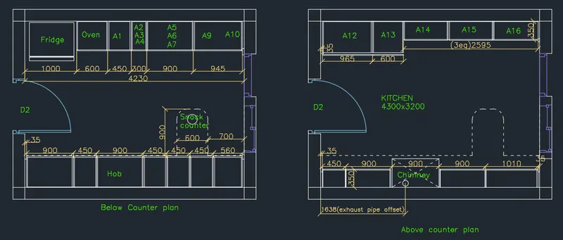
Creating a Wardrobe detailed drawing, Floor Plan, Kitchen Layout and Column Detail using AutoCad
1.
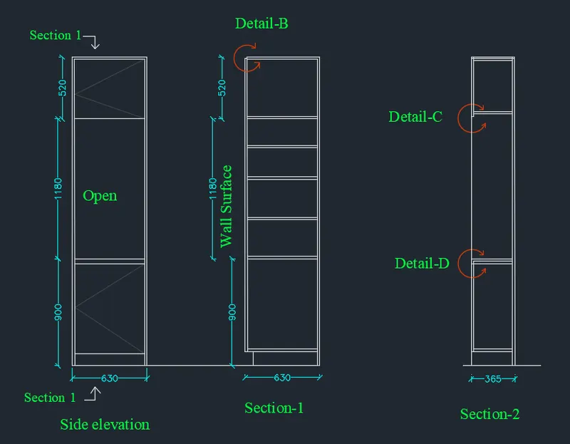
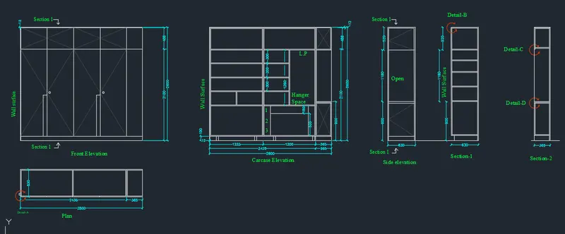
AIM: Draw the elevation and details of a wardrobe
PROCEDURE:
STEP1
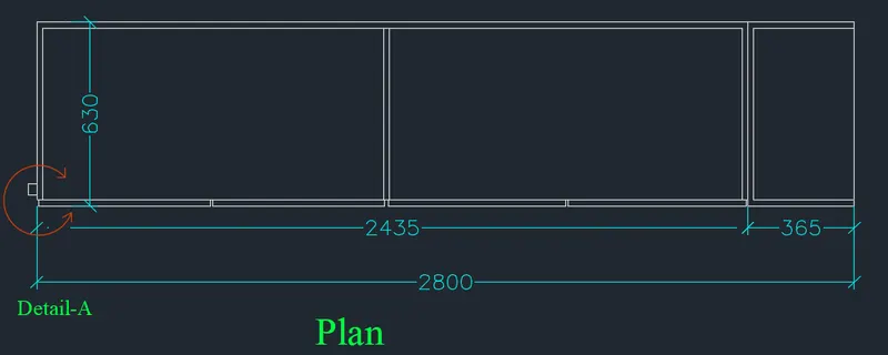
Command: L //To make the outer boundary of 2800mm & 630mm
LINE
Specify first point:
Specify next point or [Undo]
STEP2
Command: O
OFFSET
Current settings: Erase source=No Layer=Source OFFSETGAPTYPE=0 //To take offset of the above made lines to make the rectangle
Specify offset distance or [Through/Erase/Layer] <6.000>: //Offset distance of 2800 and then 630mm
Command: O
OFFSET
Current settings: Erase source=No Layer=Source OFFSETGAPTYPE=0 //To take offset of thickness of wardrode
Specify offset distance or [Through/Erase/Layer] <630.00>: //Taking thickness of 20mm & for hinges and door 6mm offset
STEP3
Command: TRIM
Current settings: Projection=UCS, Edge=None //For trimming the extra edges of the wardrobe doors and hinges
Select cutting edges ...
Command: DIMSTY //For selecting dimension style romans.shx
DIMSTYLE
STEP4
Command: XL
XLINE
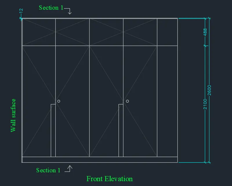
Specify a point or [Hor/Ver/Ang/Bisect/Offset]: //for taking vertical reference line for the elevation
Specify through point:
Command: L //To make a horizontal base line for elevation
LINE
Specify first point:
Specify next point or [Undo]:
Command: O
OFFSET
Current settings: Erase source=No Layer=Source OFFSETGAPTYPE=0 //To take offset of the horizontal line 2600mm
Specify offset distance or [Through/Erase/Layer] <0.000>:
STEP5
Command: O
OFFSET
Current settings: Erase source=No Layer=Source OFFSETGAPTYPE=0 //Taking offset for the middle opening of doors
Specify offset distance or [Through/Erase/Layer] <0.000>:
STEP6
Command: _text
Current text style: "Annotative" Text height: 90.000 Annotative: Yes Justify: Left
Specify start point of text or [Justify/Style]: //Type the text as required in the drawing
Specify rotation angle of text <0>:
Command: _dimlinear
Specify first extension line origin or
STEP7
Command: XL
XLINE
Specify a point or [Hor/Ver/Ang/Bisect/Offset]: //for taking the horizontal eference of the height
Command: L //To make a horizontal base line for elevation
LINE
Specify first point:
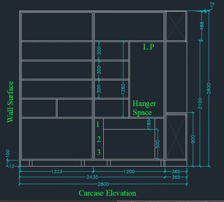
Specify next point or [Undo]: //To make a vertical line for the left side of carcase elevation
STEP8
Command: TRIM
Current settings: Projection=UCS, Edge=None //For trimming the extra edges of the wardrobe doors and hinges
Select cutting edges ...
Command: O
OFFSET
Current settings: Erase source=No Layer=Source OFFSETGAPTYPE=0 //Taking offset for the width of the wardrobe 2800mm
Specify offset distance or [Through/Erase/Layer] <0.000>:
//Using offset and trim command make 12mm thickness wall,and 20mm partition wall oof wardrobe accor. to drawing
STEP8
//Use Text command and Single line command to put dimensions and text to the drawing
STEP8
Command: XL
XLINE
Specify a point or [Hor/Ver/Ang/Bisect/Offset]: //for taking the horizontal eference of the height for the section1-2 and side elevation
Command: O
OFFSET
Current settings: Erase source=No Layer=Source OFFSETGAPTYPE=0 //Taking offset for the width side elevation
Specify offset distance or [Through/Erase/Layer] <0.000>: 630 //Similarly taking off set for section1630mm §ion 2 drawings365mm
STEP9
Command: O
OFFSET
Current settings: Erase source=No Layer=Source OFFSETGAPTYPE=0 //Taking offset for hickness of wardrobes
Specify offset distance or [Through/Erase/Layer] <630.000>: 20
STEP10
Command: TRIM
Current settings: Projection=UCS, Edge=None //For trimming the extra edges of the wardrobe doors and hinges
Select cutting edges ...
Command: CO
COPY //To copy the arc for showing the movement of the doors from the plan drawing
Select objects: 1 found
Select objects:
Current settings: Copy mode = Multiple
STEP11
Command: _text
Current text style: "Annotative" Text height: 90.000 Annotative: Yes Justify: Left //To type the text as per the drawing rotaion angle 0
Specify start point of text or [Justify/Style]:
Specify rotation angle of text <0>:
Command: _dimlinear
Specify first extension line origin or
RESULT:
2.
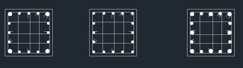
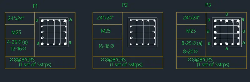
AIM: Sketch the column details as shown in Figure
PROCEDURE:
STEP1
Command: RECTANG
Specify first corner point or [Chamfer/Elevation/Fillet/Thickness/Width]: //Making the column size
Specify other corner point or [Area/Dimensions/Rotation]: @24,24
STEP2
Command: O
OFFSET
Current settings: Erase source=No Layer=Source OFFSETGAPTYPE=0
Specify offset distance or [Through/Erase/Layer] <4.75>: 1.5 //Making clear cover of column
STEP3
Command: _circle
Specify center point for circle or [3P/2P/Ttr (tan tan radius)]: _ttr
Specify point on object for first tangent of circle:
Specify point on object for second tangent of circle:
Specify radius of circle <0.78>: 0.5 //MAking the reinforcement and circle of 0.34inch
STEP4
Command: CO
COPY //To copy the circles to the corners of the stirrups and the other circles at the location
Select objects: 1 found
Select objects:
Current settings: Copy mode = Multiple
STEP5
Command: F
FILLET
Current settings: Mode = TRIM, Radius = 0.62
Select first object or [Undo/Polyline/Radius/Trim/Multiple]: 0.5 //Using fillet for the corners of the stirrups Radius 0.5 or 1Dia
ommand: L
LINE
Specify first point: _tan to
Specify next point or [Undo]: _tan to //Making the stirrups connection to the column reinforcement
STEP6
Command: CO
COPY //copy the P1 Drawing and paste it at side and
Select objects: 1 found
Select objects:
Current settings: Copy mode = Multiple
//Repeat the same procedure as above and change the reinforcement dia according to the drawing
STEP7
Command: LINE
Specify first point: //Using line command to make the table
Specify next point or [Undo]:
Command: _text
Current text style: "Standard" Text height: 3.00 Annotative: No Justify: Left //Using Text of 3inch height to write details
Specify start point of text or [Justify/Style]:
RESULT:
3.
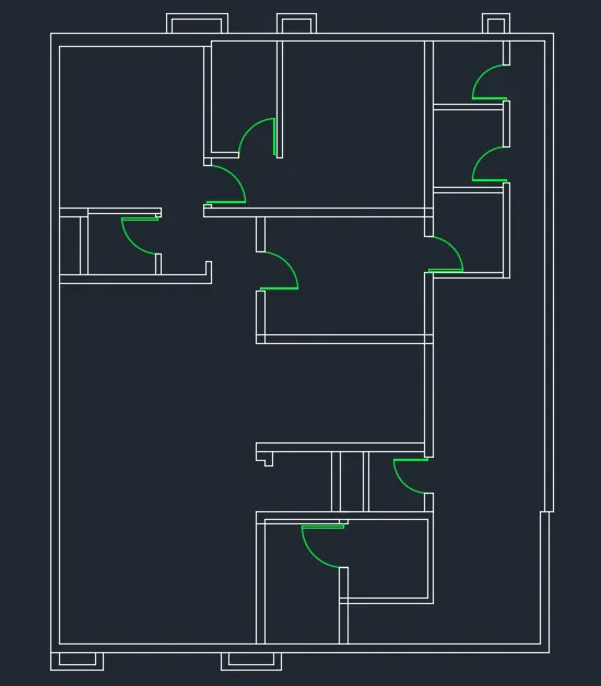
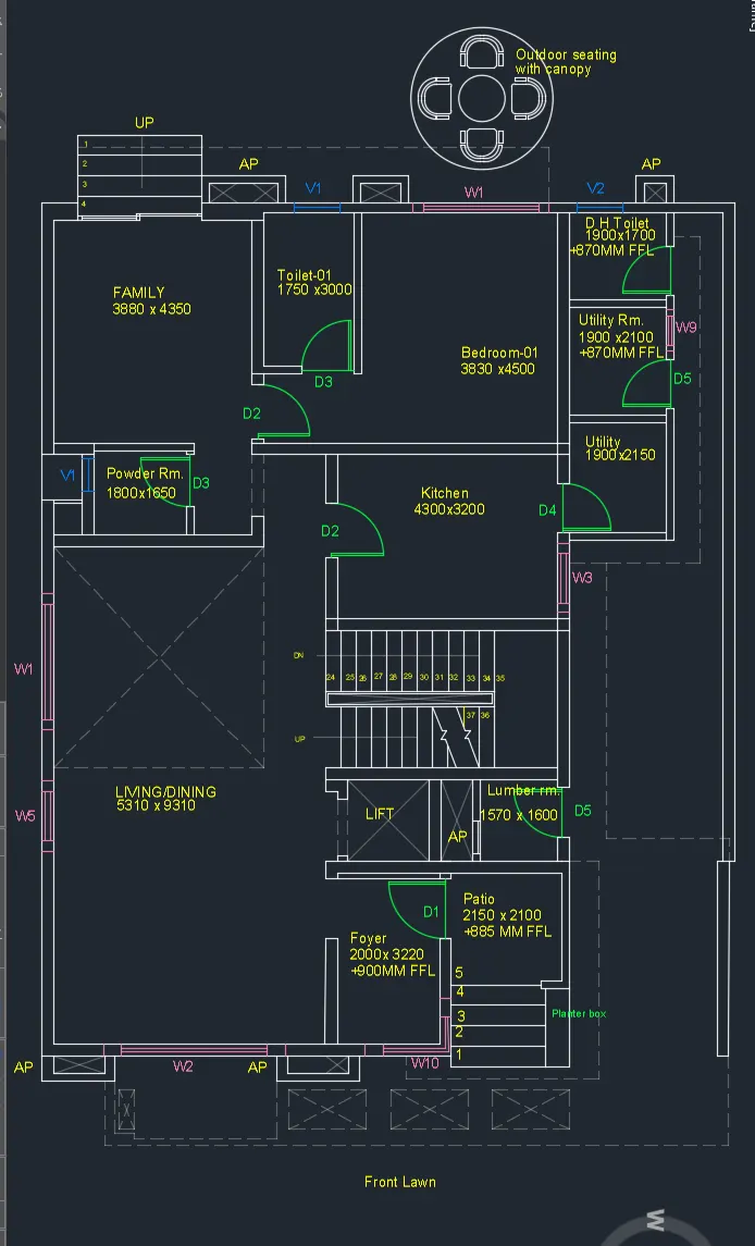
AIM:Draw the floor plan as shown in the Figure.
PROCEDURE
STEP1
Command: XL
XLINE
Specify a point or [Hor/Ver/Ang/Bisect/Offset]: //for taking the horizontal and vertical line for the left down corner
Command: O
OFFSET
Current settings: Erase source=No Layer=Source OFFSETGAPTYPE=0 //Taking offset for the width of walls
Specify offset distance or [Through/Erase/Layer] <0.000>: 230 //width of exterior wall
STEP2
Command: F
FILLET
Current settings: Mode = TRIM, Radius = 50.000
Select first object or [Undo/Polyline/Radius/Trim/Multiple]: r
Specify fillet radius <50.000>: 0 //For joing lines at the corners
Command: O
OFFSET
Current settings: Erase source=No Layer=Source OFFSETGAPTYPE=0 //Taking offset for the width of walls
Specify offset distance or [Through/Erase/Layer] <230.00>: 5310 //width of living/dining room
//Similarly using offset draw the size of length of living room 9310
STEP3
Command: O
OFFSET
Current settings: Erase source=No Layer=Source OFFSETGAPTYPE=0 //Taking offset for the width of walls
Specify offset distance or [Through/Erase/Layer] <230.00>: 230 //exterior walls
//Using offset for making the exterior and internal walls 150mm wherever required
Command: TRIM
Current settings: Projection=UCS, Edge=None //For trimming the extra lines going out the size of room
Select cutting edges ...
//Using all the above methods draw the walls of the house plan as shown
STEP4
Got to layer properties and make the layers of "DOOR"
Select colour
Command: _line
Specify first point: //Drawing hinges and door panel
Specify next point or [Undo]:
Command: _circle //To drwa the sqing path of the door
Specify center point for circle or [3P/2P/Ttr (tan tan radius)]:
Specify radius of circle or [Diameter]:
Command: *Cancel*
STEP5
Command: TR
TRIM
Current settings: Projection=UCS, Edge=None //trim the extra circle circumference
Select cutting edges ...
Select objects or <select all>:
Command: CO
COPY //To copy and paste the door at the places required
Select objects: 1 found
Select objects:
Current settings: Copy mode = Multiple
STEP6
Make a layer of name dotted linetype and make the open parking areas of house
Command: _circle
Specify center point for circle or [3P/2P/Ttr (tan tan radius)]:
Specify radius of circle or [Diameter] <1412.761>: //For making inner and outer circle of canopy
Command: *Cancel*
Command: _rectang
Specify first corner point or [Chamfer/Elevation/Fillet/Thickness/Width]: // for making seat
Specify other corner point or [Area/Dimensions/Rotation]:
Command: F
FILLET
Current settings: Mode = TRIM, Radius = 200 //For making curve edges of the seating
Select first object or [Undo/Polyline/Radius/Trim/Multiple]: r
Specify fillet radius <200.000>: 0
STEP7
Command: O
OFFSET
Current settings: Erase source=No Layer=Source OFFSETGAPTYPE=0 //Taking offset for the handrest
Specify offset distance or [Through/Erase/Layer] <230.00>:50 //taking 70 offset for the width of handrest
Command: TRIM
Current settings: Projection=UCS, Edge=None //For trimming the extra lines of the hand rest
Select cutting edges ...
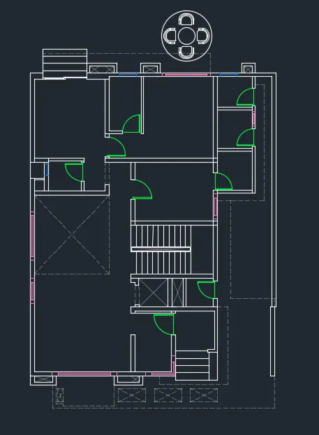
STEP7
Command:LA
Layers
create a layer of texts and choose the colour for it
Enter the texts as required in the drawing along with the dimensions
RESULT:
4.
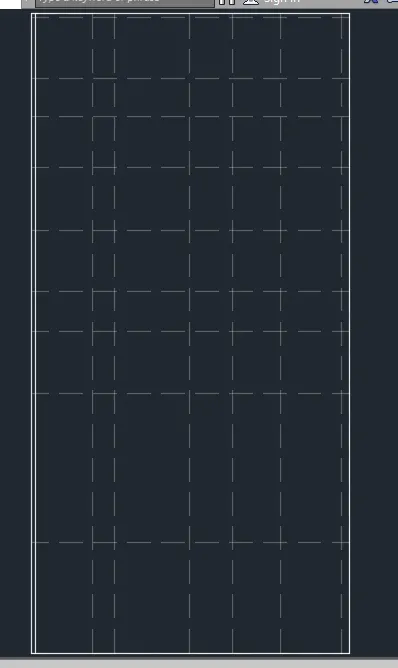
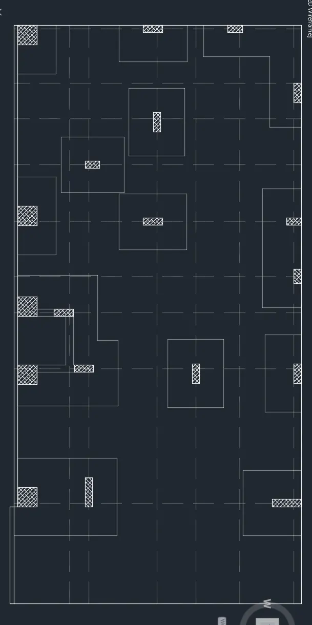
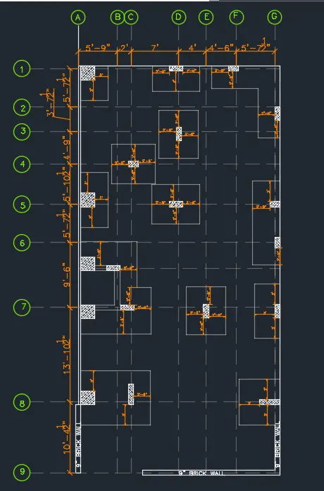
AIM: Draw the Raft Layout as shown in the Figure.
PROCEDURE:
STEP1
Command: XL
XLINE
Specify a point or [Hor/Ver/Ang/Bisect/Offset]: //for making a vertical line and horizontal line
Command: O
OFFSET
Current settings: Erase source=No Layer=Source OFFSETGAPTYPE=0 //Taking offset the size of foundation
Specify offset distance or [Through/Erase/Layer] <0'.00">:59'3" //taking offset for the hosrizontal limits
//Similarly take offset of vertical line of 28'10.5"
STEP2
Command: TR
TRIM
Current settings: Projection=UCS, Edge=None //trim the extra extended lines of the boundry
Select cutting edges ...
Select objects or <select all>:
STEP3
Command: LA
Layer ,Create of layer of 80% transparency and dashed line type
Command: O
OFFSET
Current settings: Erase source=No Layer=Source OFFSETGAPTYPE=0 //Take off of vertical dashed line
Specify offset distance or [Through/Erase/Layer] <0'.00">:5'9" //similarly take off set for 2',7',4',4'6",4'7.5" respectively
Command: O
OFFSET
Current settings: Erase source=No Layer=Source OFFSETGAPTYPE=0 //Take off of horizontal dashed line
Specify offset distance or [Through/Erase/Layer] <0'.00">:4'7.5" //Take offset from top 5'7.5",3'7.5",4'9",5'10.5",5'7.5",9'6",13'10.5",10'4.5" respectively
STEP4
Command: REC
RECTANG
Specify first corner point or [Chamfer/Elevation/Fillet/Thickness/Width]: //Making column sizes
Specify other corner point or [Area/Dimensions/Rotation]: @24,24
Command: RECTANG
Specify first corner point or [Chamfer/Elevation/Fillet/Thickness/Width]:
Specify other corner point or [Area/Dimensions/Rotation]: @9,24
Command: RECTANG
Specify first corner point or [Chamfer/Elevation/Fillet/Thickness/Width]:
Specify other corner point or [Area/Dimensions/Rotation]: @9,18
STEP5
Command: _hatch
Pick internal point or [Select objects/Undo/seTtings]: Selecting everything... //To make hatching of the columns
Selecting everything visible...
Command: CO
COPY //copy the columns to their required places in the footing
Select objects: 1 found
Select objects:
Current settings: Copy mode = Multiple
STEP6
Command: DIMLIN
DIMLINEAR
Specify first extension line origin or <select object>: //insert the dimension for the sizes
Specify second extension line origin:
Command: _text
Current text style: "Standard" Text height: 0'-10.0" Annotative: No Justify: Left
Specify start point of text or [Justify/Style]: //Write the column lines with the text
Specify rotation angle of text <0>: 0
RESULT:
4.
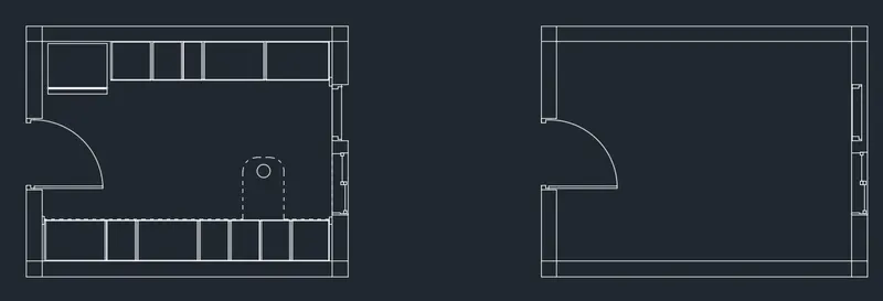
AIM: Create the Kitchen Layout as shown in the Figure .
PROCEDURE:
STEP1
Command: XL
XLINE
Specify a point or [Hor/Ver/Ang/Bisect/Offset]: //for making a vertical line and horizontal line
Command: O
OFFSET
Current settings: Erase source=No Layer=Source OFFSETGAPTYPE=0
Specify offset distance or [Through/Erase/Layer] <0.00>:230 //taking offset for the wall thickness
STEP2
Command: RECTANG
Specify first corner point or [Chamfer/Elevation/Fillet/Thickness/Width]:
Specify other corner point or [Area/Dimensions/Rotation]: //For making the size for fridge
Command: O
OFFSET
Current settings: Erase source=No Layer=Source OFFSETGAPTYPE=0
Specify offset distance or [Through/Erase/Layer] <0.00>:230 //taking offset for the different compartment of the kitchen
//Taking offset from horizontal and vertical lines and making the compartments using the above steps
STEP3
Command: TR
TRIM
Current settings: Projection=UCS, Edge=None //trim the extra extended lines of the boundry
Select cutting edges ...
Select objects or <select all>:
STEP4
Command: _line
Specify first point: //Drawing hinges for the door from the reference
Specify next point or [Undo]:
Command: _circle //To draw the swing path of the door
Specify center point for circle or [3P/2P/Ttr (tan tan radius)]:
Specify radius of circle or [Diameter]:
Command: *Cancel*
Command: TR
TRIM
Current settings: Projection=UCS, Edge=None //trim the extra extended lines of the boundry
Select cutting edges ...
Select objects or <select all>:
STEP5
Command:LA
LAYER
create a layer of dashed linetype
Command: _line
Specify first point: //Drawing dashed lines for the snack counter
Specify next point or [Undo]:
Command: O
OFFSET
Current settings: Erase source=No Layer=Source OFFSETGAPTYPE=0
Specify offset distance or [Through/Erase/Layer] <0.00>:700 //taking offset for snack desk
//Repeat the above method to draw the seconf drawing according to the dimensions given
STEP6
Command: DIMLIN
DIMLINEAR
Specify first extension line origin or <select object>: //insert the dimension for the sizes
Specify second extension line origin:
Command: DIMCONT
DIMCONTINUE
Select continued dimension:
Specify second extension line origin or [Select/Undo] <Select>: //continous dimensions for continous dimension
Enter dimension text <0.00>: ______
Command: _text
Current text style: "Standard" Text height: 100.00 Annotative: No Justify: Left
Specify start point of text or [Justify/Style]: //Write the texts of the kitchen and the spaces
Specify rotation angle of text <0>: 0
RESULT: