Modelling of 25 storey building with the specified properties using ETABS
6
AIM: ETABS modelling of a 25 storey building
Model a 25 storey building on ETABS with structural properties as specified below. Ground floor or plinth floor level can be taken at a height of 1.5 metres from the base. Each of the successive 25 storeys has a storey height of 3 metres.
PROCEDURE:
STEP1
- Open E-Tabs ->new file
- A new tab will open
-
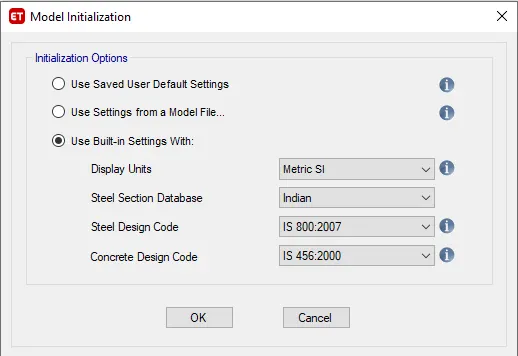
- Use built in settings ->change the units and codes as per indian standard->Click Ok
- A new tab will open
STEP2
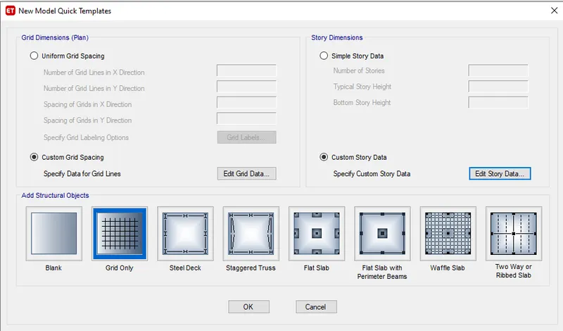
- Click on custom grid spacing->Edit grid data->A new tab will open
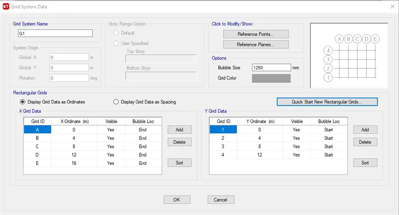
- Enter the grids ordinates in X direction And Y direction
- Click on Add to made more grids as pers requirement->Click on Ok
- You will be brought back to the previous page(Quick templates page)
- Click on custom storey data->A new tab will open
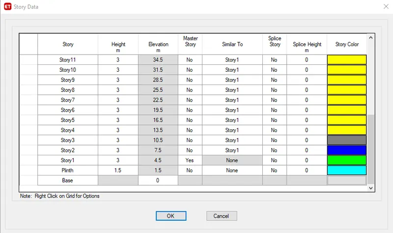
- Right click on and select "add new story"->Enter number of story you want->enter distance between them
- Select story 1 as the master story and all athers as No(as shown in the above pic)
- Select siimilar to "Story 1"->SO that all other story will be similar to story 1
- Click Ok
STEP3
- Will be taken to template page->click Ok
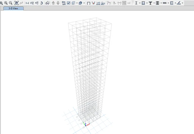
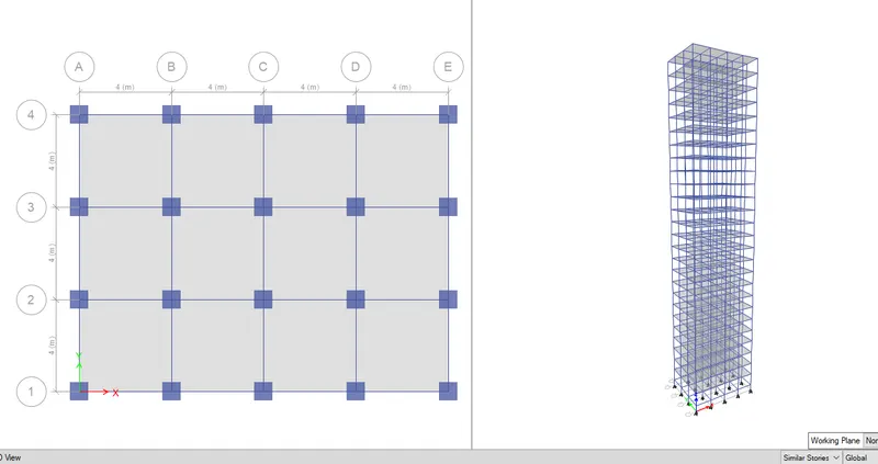
- The main page will open showing the building structure you designed(shown below)
STEP4
- Click on Define bar->material properties->a new tab opens
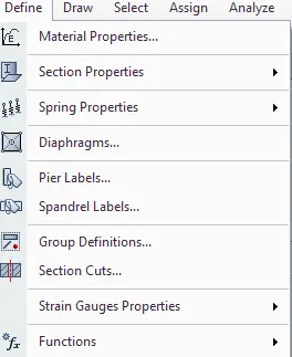
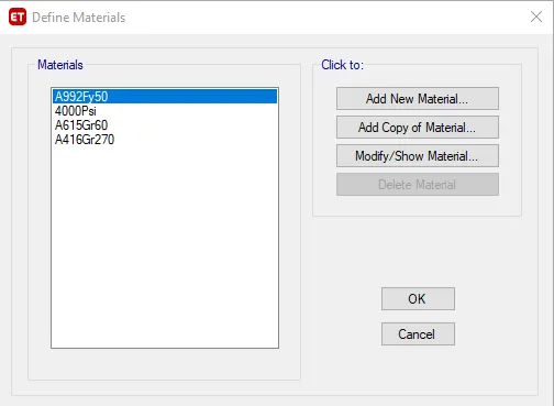
- after selecting material properties->new tab will open
STEP5
- Click on add new material->New tab opens-.selct as per the standard(concrete/rebar etc.)
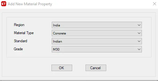
- Next we need to check material property data
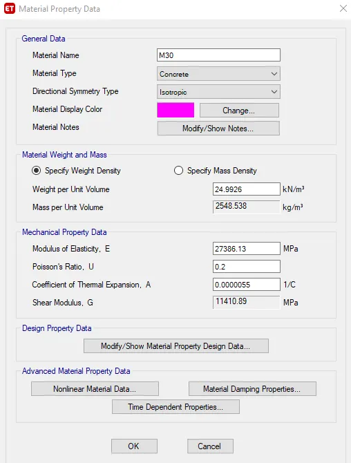
STEP6
- Next we need to add rebar as the materail
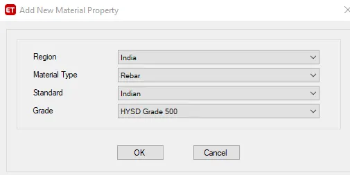
- we need to check material property data of the HYSD bar
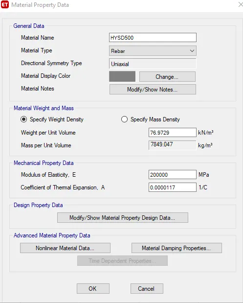
- click on OK
STEP7
- Also do the same for 415 rebar similar ot the abive 500HYSD
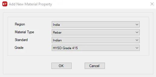
STEP8
- After adding the material properties->we have to add the column and beams sections
- Go to define->section properties->frame sections
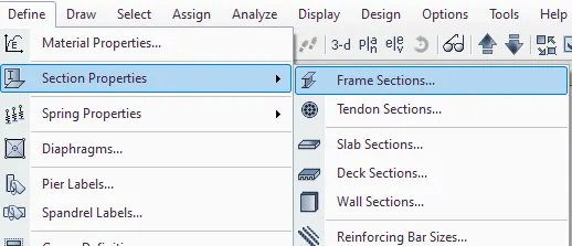
- a new tab will open->Click on Add new property
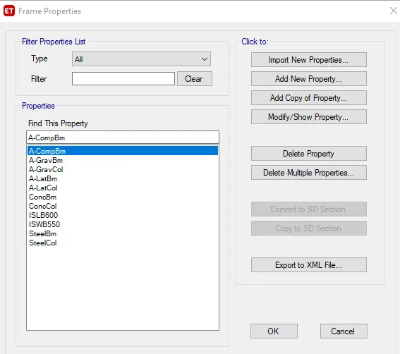
STEP9
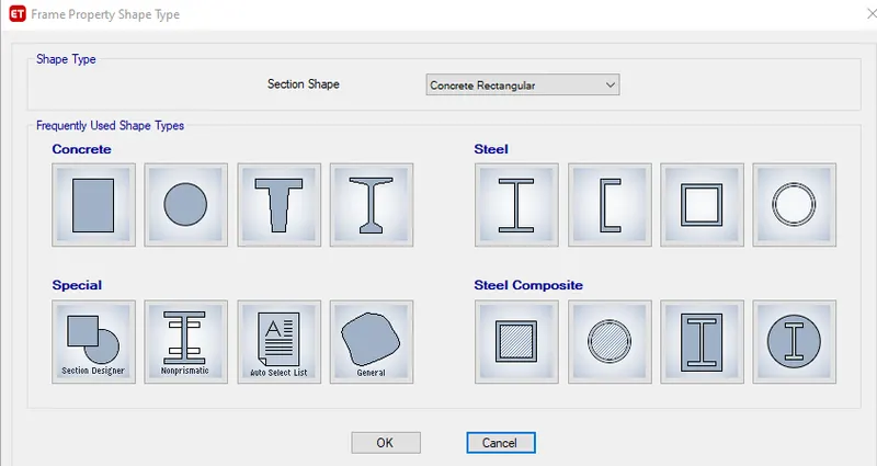
- After click add new property->A new tab open ->from here select the rectangular concrete and click ok
- To add new beam and column frames
- Next a frame section property data will open->you have to enter the data for the beam and columns
- Change the property name as pers given data B300x400->change material in to M30
- enter the depth and widht of the sections
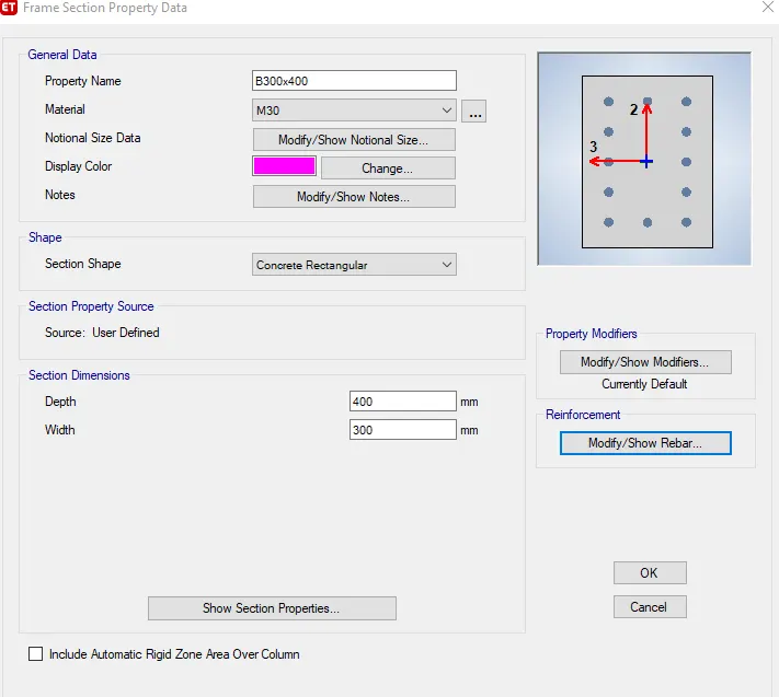
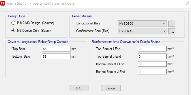
- Click on Modify/show rebar->to enter the rebars types and numbers
- A new tab will open->click on M3 design only
- Change longitudnal bars and Ties bar types to the one you made before
- Enter the covers distance ->click on OK
STEP10
- Again on frame sections->Add new property
- Select the rectangular concrete section->click on OK
- A new tab open->rename the property as C800x800
- Enter the width and depth of the column
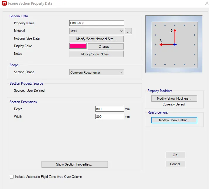
- Click on modify/show rebar->To enter the bars type of clumns
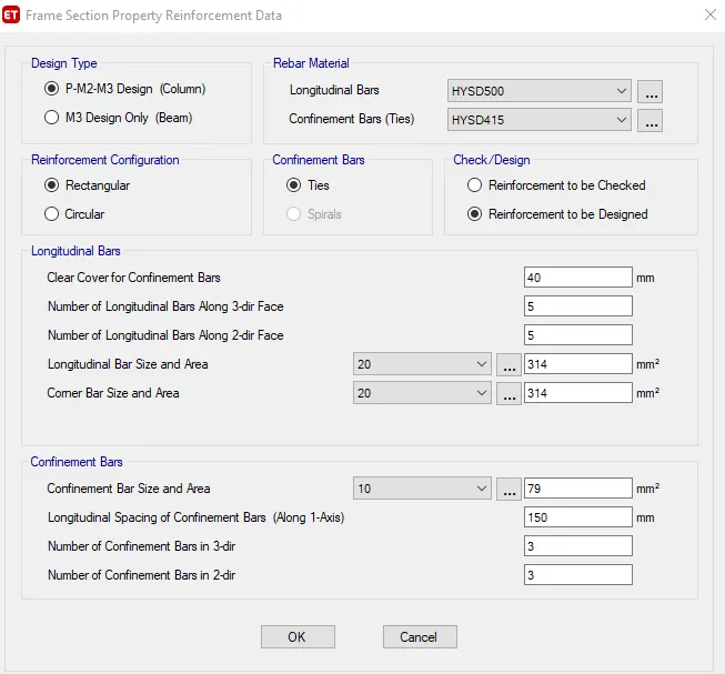
- A new tab will open->click on P-M2-M3 design->Enter longitudnal and tie bars type
- reinforcement to be designed->Enter the number of bars your want in 2&3 direction
STEP11
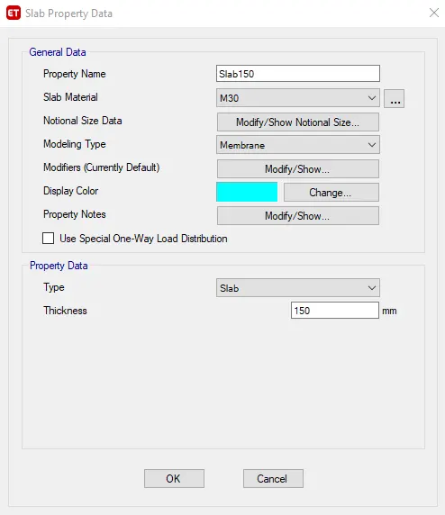
- Next we select the slab section for the slab of 150mm
- Go to define->section properties->slab sections
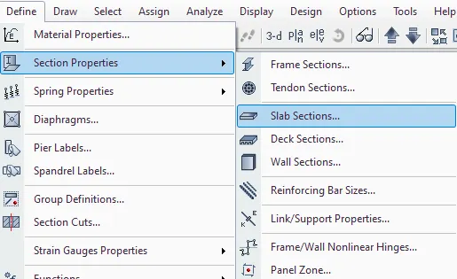
- A slab properties tab will open->Click on slab1 ->modify/Show property
- Slab property data tab will open->rename the slab as Slab150
- select the slab material as M30->Modeling type as "membrane"
- enter the thickness of the slab->click OK
STEP12
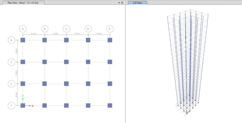
- Now we will add columns to the structure.
- Go to bottom right corner and select ALL STORIES
- Click on "Quick draw columns" of left side toolbars->a new tab will open
- select the C800x800 from the property
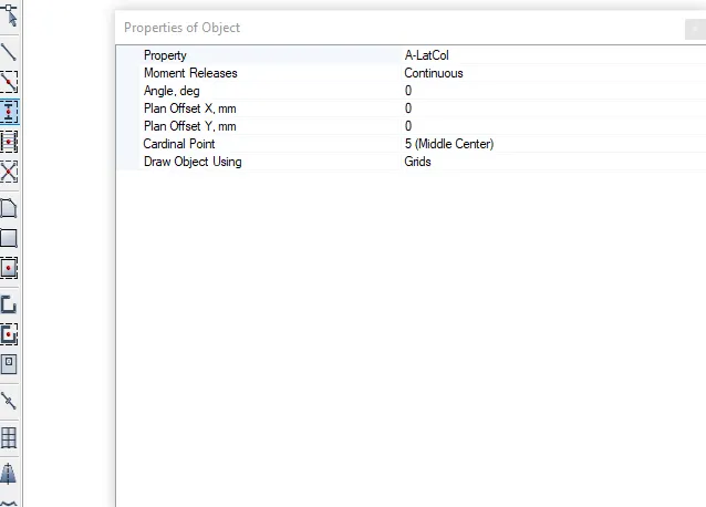
- select all the columns ->all the columns will be applied to the grids
STEP13
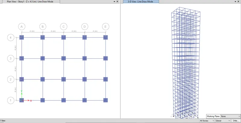
- Now beam will be added->Select quick draw beams (keep the selection to ALL stories)
- a tab will open->select the property to B300x400
- select all the beams section->the beams will be applied
STEP14
- Now add slabs to the section-Select quick draw floors/Slabs
- a tab will open->change the property to slab 150
- Change the selection To similar stories
- select all the slabs of any one floor ->the floors will be applied
 15
15
STEP15
- Now joints will be added to the base
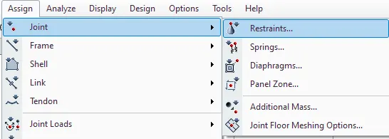
- Goto Assign bar->Joints->Restraints
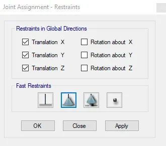
- A new Joint assignment tab will open->select the pin joint
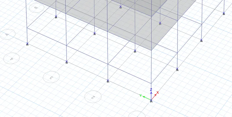
- Now the pin joint is assigned to the base of the columns
STEP16
- Now we need to define load patterns->Go to Define Bar "Load patterns"
- Add dead load ,live load,brickwall load and earthquake load as shown below
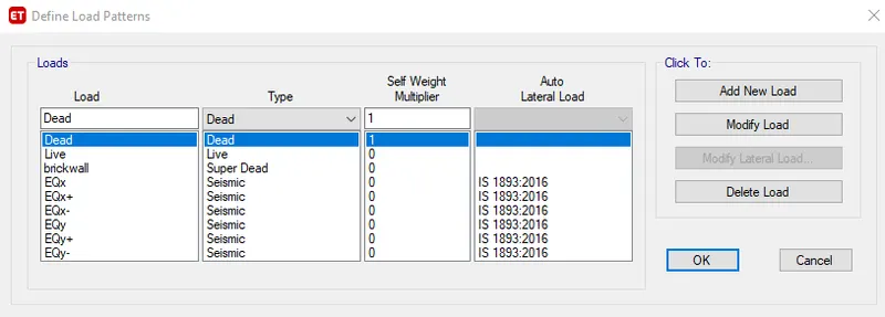
- Now we have to modify the earthquake load as per the direction of applications
- To modify ,click on earthquake loads "EQx-" ->CLick on Modify lateral load
- A new tab will open-> select only the Load direction you want(X dir-eccentricity in this case)
- Select Site III as suggested in the question & time period user defined 0.5 sec
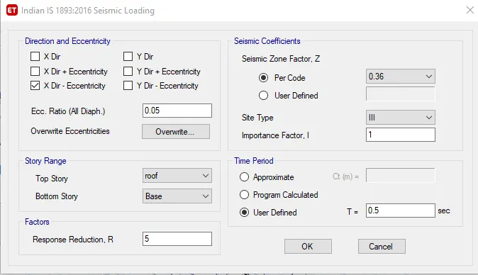
//Do this for all the earthquake directions,just change the eccentricity and direction in the above
STEP17
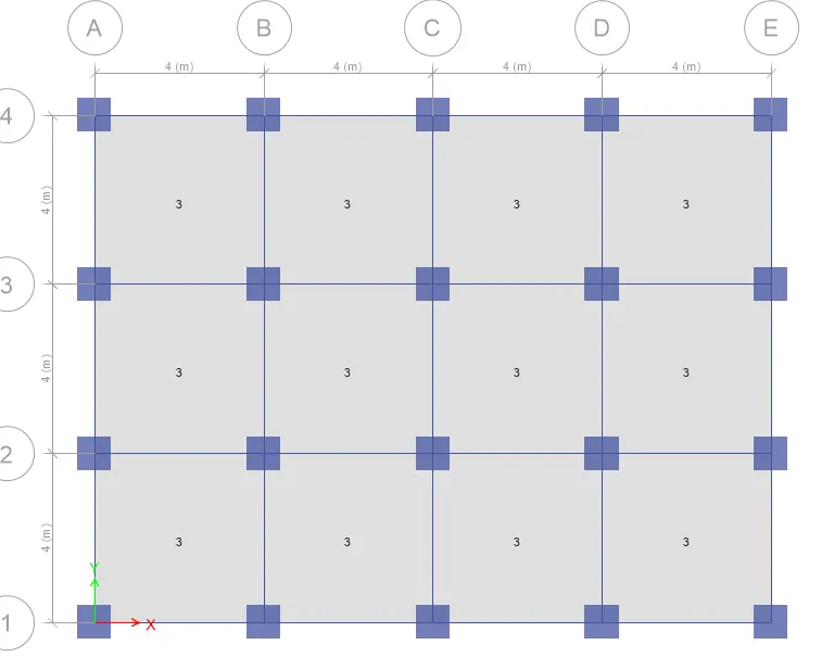
- Now we have to assign the live load to the slabs and brick wall loads
- Select all the slabs of any floor
- Go to Assign->Shell loads->Uniform
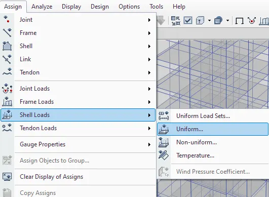
- A Shell load assignment will open->Input a live load of 3 KN/m^2 as per the question
- Make sure the similar stories are selected
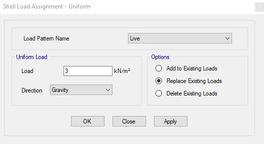
- Now the live load is applied to all the floors
STEP18
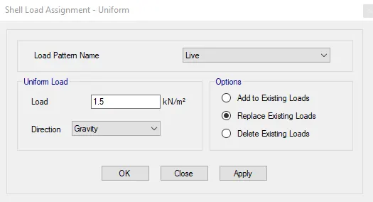
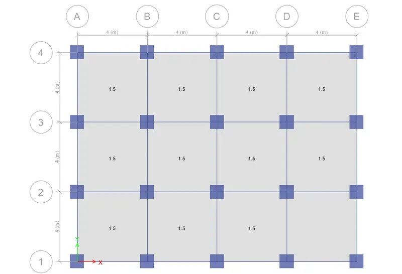
- Now the live load will be applied on the roof
- Go to the roof plan->Change the selection into One story
- select all the slabs of the roof
- Go to assign->shell loads->Uniform
- Put live load of 1.5KN/m^2 (the roof has live load of 50% of the floor)
STEP19
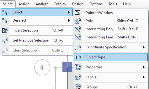
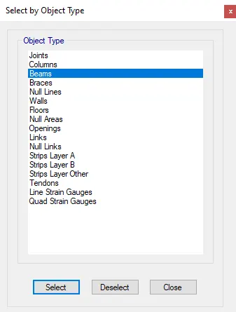
- Now assigning the brickwall load to the beams //Make sure u change the selection to all stories
- GO to select menu->object types->select beams(all beams will be selected)
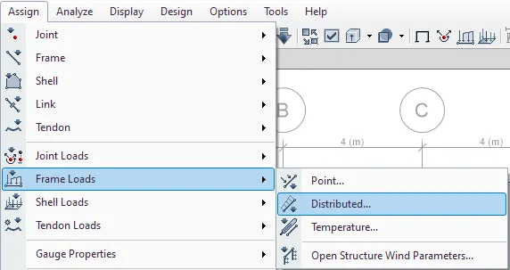
- Now go to Assign menu->Frame load->distributed
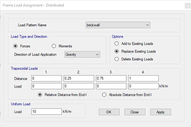
- load assessment tab will open->select the brickwall from the selection
- enter the value of 10KN/m
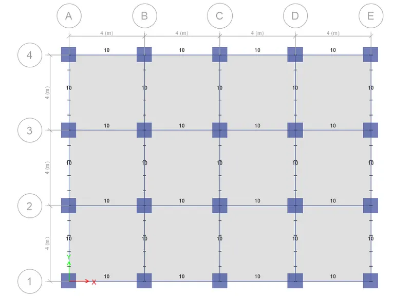
- brickwall is districbuted all over beams
STEP20
- Now we define mass source
- Go to Assign Menu->MAss source
- A new tab will open->Click on Modify/show mass source
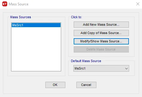
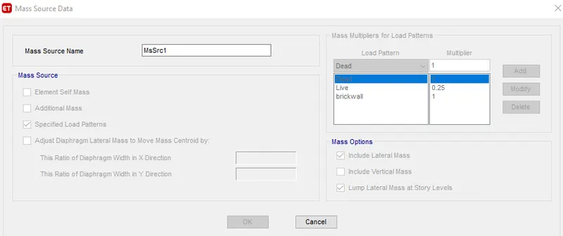
- modify tab will open->select specified load patterns
- Input dead=1,brickwall-1,live=0.25
STEP21
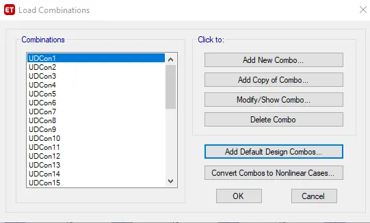
- Now load combination will be defined
- From the define menu->go to load combination
- a new tab will open->click on Add default design combos
- Select concrete frame design
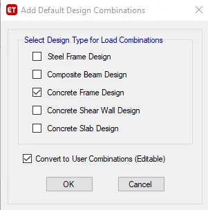
- Click oK
STEP22
- MAking the diaphragm of the structure
- Go to select menu->object types->seelct the floors
- Assign->Shell->Diaphragm
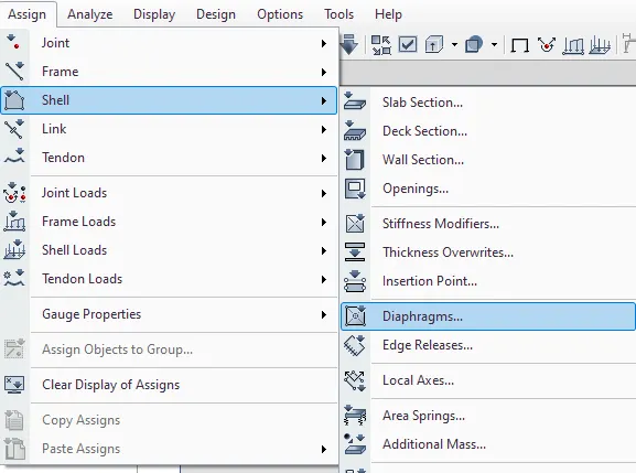
- A new tab will open->in that select D1 and apply
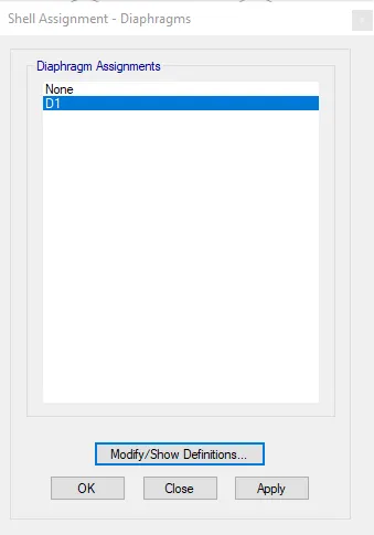
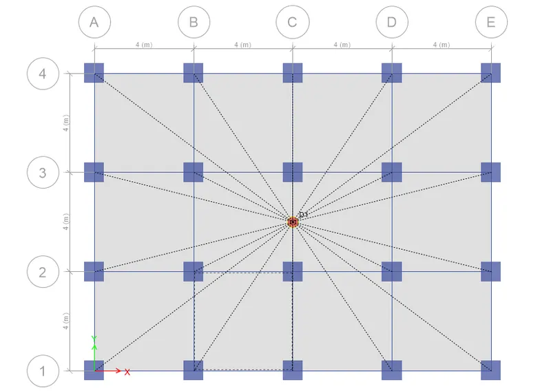
STEP23
- Now we check the model for errors
- Go to analyze menu->check model
- A new tab opens->tick all the checks
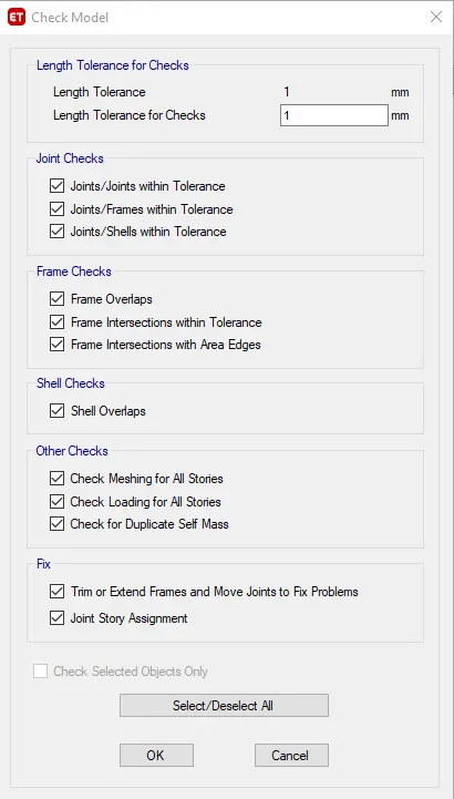
- A no error mesage will be shown if there are no errors in the structure
STEP24
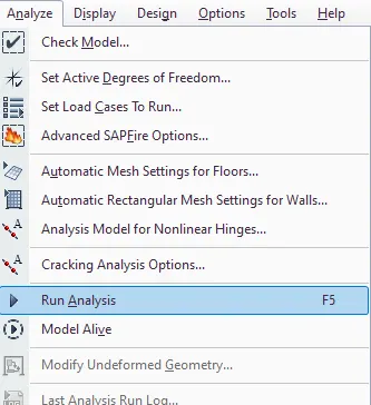
- Now Go to analyze menu->run analysis->analysis will take some minutes
- Go to "Show deformed shape or F6"->Tab will open and select any case(live/dead,earthquake) you want view the deformed shape
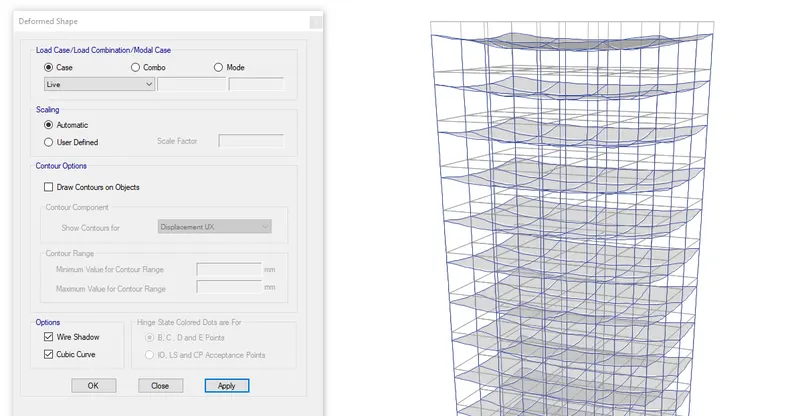
//Check on all other cases and see the deformed shapes
STEP25
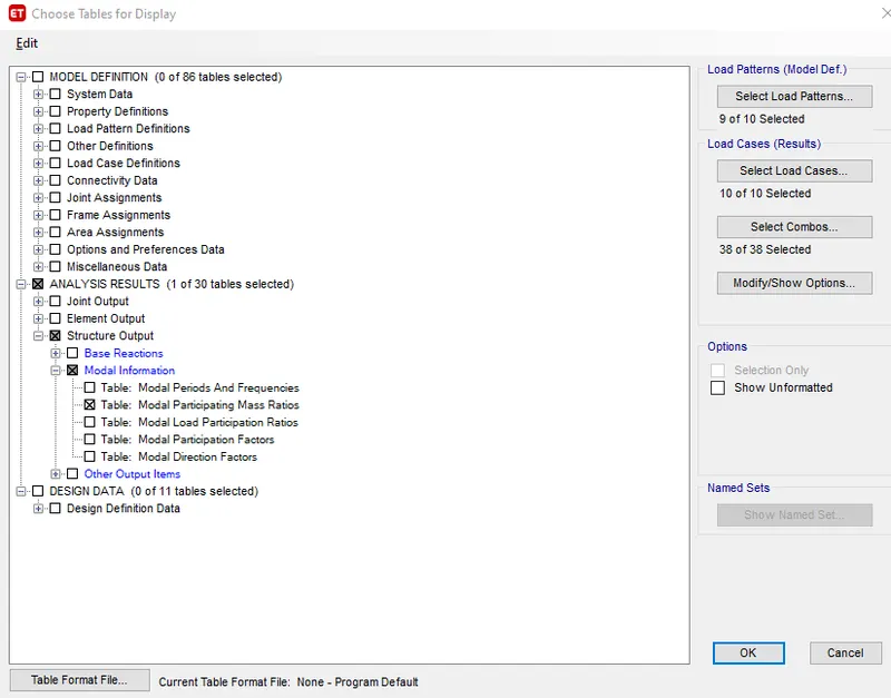
- click on Display menu->Show tables->TAbles display will open
- select anaylysis results->structure output->modal information->Modal participation mass ratios
- A Modal participation mass ratios table will appear with all the mass ratios action on the builidng
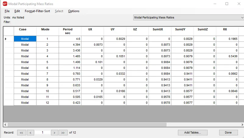
- From table Natural time period of mode1 is noted and torsional DOF is noted
- Tx1=4.6sec,Ty1=4.394sec and Txy=3.436sec
- so it is clear from the table that the torsional time periiod is less than the two translational time period as required by IS 1893 provision table 5
CONCLUSION:The analysis is done and the result is within the range