Creating Kitchen layout, Hatching of Architectural elements and sectional view of an Industrial Building in AutoCad
1.
AIM: Create the layouts of the Kitchen and provide hatches pattern as shown. Also, use blocks wherever required. Provide appropriate dimensions in the plan. Assume the size of doors, appliances and others as per the standards.
PROCEDURE:
- To Make the door Block
- To make the windows and vents
- Making the kitchen layout
- To insert the hatching pattern in the required places
STEP1
Command:XLINE
- TO ddraw a line in vertical and horizontal direction
command:OFFSET
- Take a n offset of 230mm from both vertoical and horizonatla line //For making the kitcehn walls
- Take an offset of 3190 from horizontal line
- and take offset of 4230mm fro vertical line //for making the interior space of the kitchen
- Take offset of 230mm for the walls
STEP2
Command:TRIM
- Trim the extra lines of the XLINE //To make it visibly clear
Command:RECTANGLE
- Make a rectangle of 1000x750mm //For the fridge
- make a rectangle of 3195x350mm //for te stove and other spaces of kitchen
Command:OFFSET
- Take offset of 17mm from the edges of each kitchen boards . //on both the side to make the partion from each other
//similarly using rectangle and offset command make the kitchen utensils using the above methods
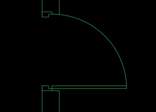
STEP3 //MAKING THE DOOR
Command:RECTANGLE
- Make a small rectangle of 128x64mm //for the border of door
- Make a rectangle of 994mmx37mm . //for the door panel from th edge of door border
Command :CIRCLE
- Make a circle ,center point from the door hinges to the outer part of the door
Command:BLOCK
- Select the door,click enter
- Name the object as "door1"
- select the coner of the door as basepoint,click OK //To make the object as block
STEP4
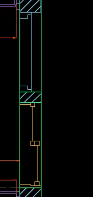
Command:RECTANGLE
- Creaye a rectangle of 230mmx906mm
- Create a small square box inside of 45mm //Fo the window slider
Command:LINE
- Connect the lines of the rectangle //To show as the glass of windows
Command:BLOCK
- Select the door,click enter
- Name the object as "door1"
- select the coner of the door as basepoint,click OK //To make the object as block
STEP5
Command:RECTANGLE
- create rectangle on the walls //according to the drawing for the hatches
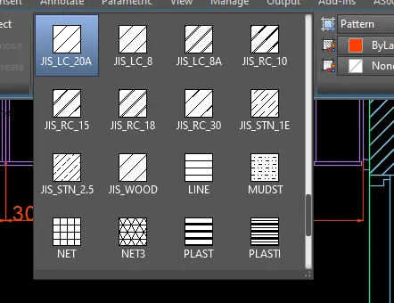
Command:HATCH
- Select the hatch pattern
- JLC_LC_20A is the pattern selected //Select the hatching pattern
- pick the internal point iside the rectangles made
STEP6
Command:LAYER
- Create the new layer
- Name the layer as Walls. //Similarly create layers ofr text dimension,windows kitchen
- Select the objects and click on the laeyer //To assign the properties of the layers
Command:DIMLINEAR
- Click on two point to show the distance between them //After making the dimension assign the property
Command:TEXT
- Click on the location u want to write text
- specify the angle for the text
- Type the text as required.
STEP7
Command:INSERT
- Insert click n the block u want to insert
- select the object scale and rotation
- place the object where u want o place it //helps in using the block we made easily
//Using the above methods and INSERT command make the other kitchen plan
RESULT:
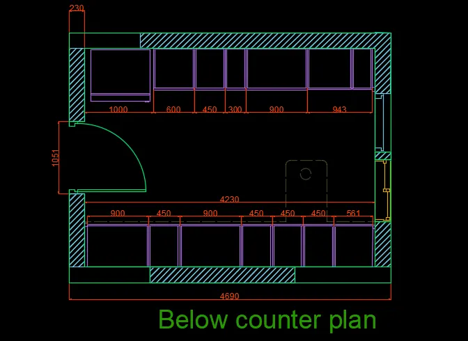
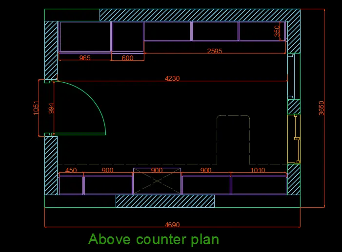
2.
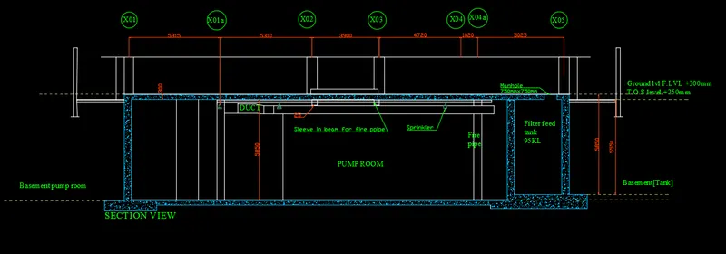
AIM:Create the section view of an industrial building as shown in Figure. Provide appropriate hatches and dimensions wherever required. Also, provide annotations to the drawing.
PROCEDURE:
- to make the outline boundary of the drawing
- drawing the ground level and sprinklers
- creating hatches
- Writing texts
- Writing dimensions
STEP1
Command:XLINE
- Create an horizontal line //for the top level base
Command:LINE
- draw a line of length 2144mm vertically //For the pipeline
STEP2
Command:OFFSET
- Take an offset of vertical line of 554mm //For thickness of pipe
- take an offset of 10078mm for the distance between pipes
- then again offset of 554mm
- take offset of 3317mm //Distance between pipes
- Take an offset of 2144mm of horizontal line //In downwards direction
- Take offset of horizontal line of 300mm
Command:LINE
- Draw a line of 2756mm from the side horizontally //for the side channel
STEP3
Command:COPY
- Copy the line
- select the basepoint and paste it at some distances
Command:RECTANGLE
- From the endpoint of the above line create a reactangle //203mmX 4026mm
STEP4
Command:MIRROR
- Copy the side channel pipe and
- select midpoint as base
- mirror it on other side
Command:RECTANGLE
- Create a rectangle of 45673x472mm //For the duct
- On the endpoint f duct create 499x5809 size of rectangle //For the air pipes
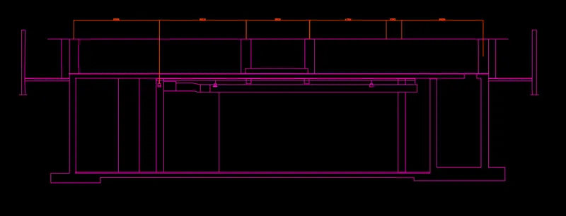
//Repeat the above process to create the section of an elevation accordin to the sizes given
STEP5
Command:LAYER
- Create layers of name walls ,texts ,dimensions,dashed lines //To create different layers accoriding to their types
Command:LINE
- Select the dashed line layer and make it current
- extend the lines from the baselines
Command:LTSCALE
- Increase or decrease the line type scale for more clear identification //to make the dashed lines visible
STEP6
Command:HATCHING
- Select the hatching "AR-CONC" //AR-CONS for showing the concrete hatching
- Pick internal points
- slect the closed region where u want the hatching pattern
STEP7Command:TEXT
- Select the text layer
- select the point where u want to type texts
- input the angle u want //to give the angle
Command:MLEADER
- SEelect the point fro the leader
- select upto the length you want the leader line
- Type the text you want to type.
Command:DIMLINEAR
- select the dimension layer
- select the two points //Point s between which u want to know the distance
//Repeat the process for different parts of the drawing to complete
RESULT:
3.
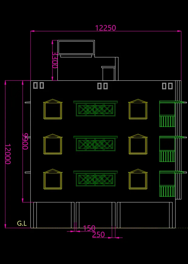
AIM:Create the section view of an industrial building as shown in Figure. Provide appropriate hatches and dimensions wherever required. Also, provide annotations to the drawing.
PROCEDURE:
- to take reference line from the week 7 drawing
- to make windows as blocks
- making vents as blocks
- making balcony
STEP1
Command:XREF
- Select PDF file
- Select the week 9 challenge
Command:XLINE
- draw the vertical line on both left and right side of the plan //To make the width of the elevation
- draw a horizontal line for the base of the elevations //Upto the depth of the elvation
- draw vertical line down for the windows and vents
STEP2
COmmand:OFFSET
- Take an offset of horizontal line from the base in upwards
- offset of 15300mm //for the total height of the elevation
- From the top roof take offset of 3300mm downwards // for the terrace height
- take offset of horisontal line 9900mm downwards // for the base of the first floor
Command:TRIM
- Trim the extra lines coming from the reference pic.
Command:LAYER
- Create layer name .walls,window1,window2,vents,G.L. line,texts,dimensions
- Assign different colours to them
STEP3
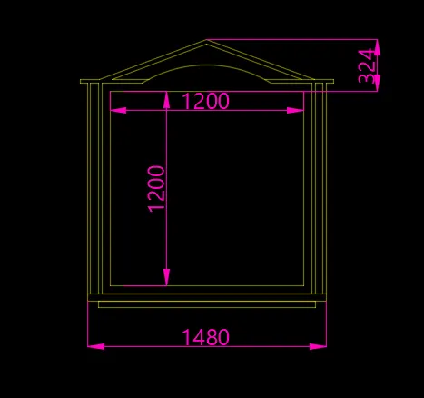
Command:RECTANGLE
- Create a rectangle of 1200mmx1200mm //For the window size
Command:OFFSET
- Take offset of 50mm outside //For window width
- Take offset of the rectangle 20mm outside //Repeat this methods 2 times
Command:CIRCLE
- From the center of the window draw a circle of 763mm
Command:LINE
- From the top of the circle draw a rectangle on atop of it //For making chhajja design
Command:BLOCKS
- Select the object,name the object
- select the basepoint //Center of the window as basepoint
- Click on turn it into block
Command:INSERT
- Insert the windows as taken refernece line from the above pdf
STEP4
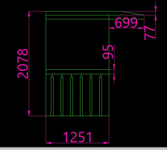
Command:RECTANGLE //MAKING THE SIDE WINDOW
- Create a rectangle of 1251x2078mm //For mking the side window
- create a rectangle from thr top of 1950mmx77 //Two times for the chhajja projection
Command:LINE
- From the edge of the window width draw angular line
- connect the start and end of the chhajja line
Command:TRIM
- TRIM the inside of the chhajja line
- and also trim the extra lines
Command:BLOCKS
- Select the object,name the object
- select the basepoint //Center of the window as basepoint
- Click on turn it into block
Command:INSERT
- Insert the windows as taken refernece line from the above pdf
STEP5 //Drawing the vents
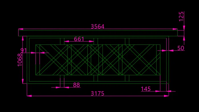
Command:RECTANGLE
- create a rectangle of 3175x1068mm
- Create a rectangle of 3564x125mm on top of the above made rectangle //For making the vent shade
Command:OFFSET //For making the vents side width of 3175x1068mm rectangle
- Take offset of rectangle 50mm inside
- take offset of the inner rectangle 145mm inside
Command:LINE
- Draw 2 vertical line 88mm apart inside the rectangle
Command:COPY
- Copy the lines and paste it at an interval of 661mm
Command:LINE
- Draw angular lines for the vents design in the innermost rectangle.
Command:BLOCKS
- Select the object,name the object
- select the basepoint //Center of the window as basepoint
- Click on turn it into block
Command:INSERT
- Insert the windows as taken refernece line from the above pdf
STEP6
Command:DIMLINEAR
- select two point between which u want to know the distance
- DIMSTYLE to change the dimesions size and style //To adjust size and text type according to need
Command:LINE
- go to G.L. Line and make it current
- Draw the ground level line //The line type is dashed
- LTSCALE to adjust the scaling
Command:TEXT
- select the text layer and make it curent //To make the text layer curent
- Select the point where u want to write text
//USE the above methods to write text and show dimension in the drawing.
RESULT: