Creating Bar Bending schedule, Different Door types, and Creation of standard drawing templates using AutoCad
1.
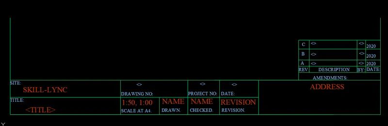
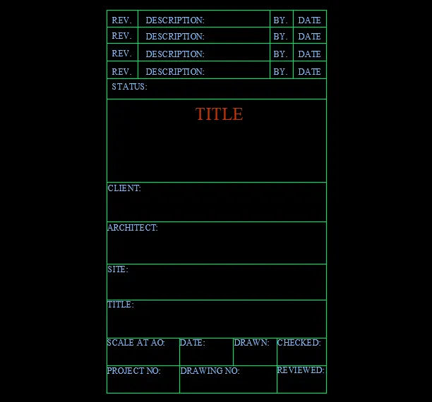
AIM:Create the templates as shown in Figures. Take the size of the title block as per industry standards or you can assume it as per the size of the paper. Use text and attributes wherever required. After creating the title block you need to save it as a block with names: Custom1_titleblock and Custom2_titleblock, respectively.
PROCEDURE:
- To create the crectangle boundary
- to create the layers
- to create the columnds and rows
- to create and type the texts.
STEP1
Command:RECTANGLE
- create the rectangle of 170mm,65mm. //Making rectangle box
Command:EXPLODE
- go to explode command.
- select the rectangle.click enter. //Explode to use it as different objects
STEP2
Command:OFFSET
- select the lower line of the rectangle. //taking offset
- enter the 7mm offset distance .
//Create the offset for the inside boxes using above step accordin to the required guidelines measurement.
Command:LAYER
- click on new layer.
- name the layers as Table,texts.
- give colours to the layers
STEP3
Command:DIMSTYLE
- To change the dimesion style accoridng to the size of the drawing
- Text height and small text height.
- create new style and name them as TEXT1 &TEXT2 //Text1 height as:2mm and TEXT2 height as:1.2mm(for smaller texts)
Command:TEXT
- click on TEXT layer and make it current. //To make it as current layer
- Select TEXT1 as the dimstyle
- Click on the area where u want to write.
- Type the text ,as for example:"TITLE:" //For making main heading
//Then select the the TEXT2 from dimstyle and make it current and make the sub-headings
STEP4
Command:COPY
- Copy the text you typed.
- paste it on the places you want write the headings
- Now,just edit the texts to the heading names u want. //shortcut method to save time and scaling text.
Command:BLOCKS
- select the object(The title block u made).
- type "blocks".
- Name the blocks Custom1_titleblock & Custom2_titleblock //To specify name to the 2 different titleblocks
- select a base point.
- Select the object. and click ok
RESULT:
Custom1_titleblock
Custom2_titleblock
2.
AIM:Create the doors type for warehouse as shown in the Figure. You need to create each door type as per standard size or given dimensions. Create the blocks of this door type after creating them.
PROCEDURE:
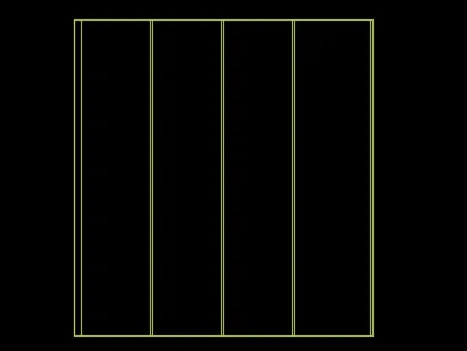
- Creating the outer boundary of the door
- Creating the panel of the door
STEP1
command:RECTANGLE
- create a rectangle of 2330,2750mm . //Making outer boundary of the door
Command:OFFSET
- take and oofset of 5mm from the below and above line //take 2 offset of 5mm for the plinth of door from top and below
- Take offset of 9mm from the below again.
- Take offset of 55 from the left horizontal line . //For the hinge of the door
- Now take offset from the line of 493mm. //For one panel of the door
//repeat the above method to make 4 Panels of the door
STEP2
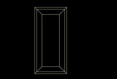
Command:RECTANGLE
- create rectangle of size 300mm,650mm //for thr panel design
Command:OFFSET
- TAke offset for 20mm inside of rectangle //For inner lines of panel design
- Take further offset of 50mm inside
Command:LINE
- Join the line corner on outer rectangle to the inner rectangle.
STEP3
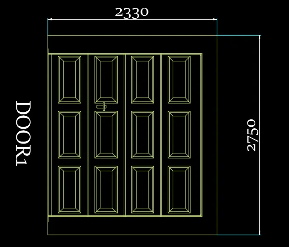
Command :COPY
- select the panel design and copy it
- select the base poin as the corner of the panel.
- place it in the middle gap of the door.
- Use ARRAY and fit at 500mm distance of 4 panel //To copy the panel design on the door
STEP4
Command:BLOCKS
- Name the block as "DOOR1"
- Select a base point . //Select the bottom middle point of door as basepoint
- select the object and click OK.
STEP5
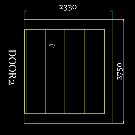
command:RECTANGLE
- create a rectangle of 2330,2750mm . //Making outer boundary of the door
Command:OFFSET
- take offset of 250mm of reactangle //To make the door size inside
Command:EXPLODE
- Click on rectangle and click enter to explode the rectangle
Command:OFFSET
- take offset of left and right vertical line of 5mm inside //hingr of door
- Take offset of 55 mm to the right and then of 493mm to the left //for making the space for the panel
STEP6
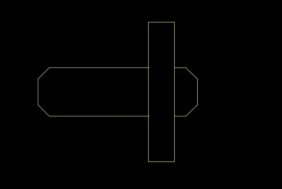
Command :RECTANGLE //to make the door handle
- Create a rectangle of 22x118mm
- create a rectangle of 118x41mm
- move one rectanlge to the other rectangle center
Command :TRIM
- trim the line passing thron the rectangle .
STEP4
Command:MOVE
- Select the door handle
- select the basepoint
- and move it to the door
Command:BLOCKS
- Name the block as "DOOR1"
- Select a base point . //Select the bottom middle point of door as basepoint
- select the object and click OK.
RESULT:
3.
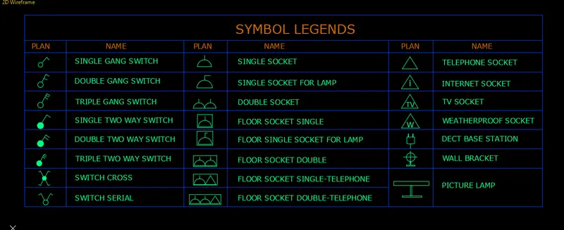
AIM:Create each symbol as a block with the name given in the legend. After creating the blocks arrange them in the legend as shown in the Figure.
PROCEDURE:
- Making the table for the legends
- making the symbols
- adding as blocks
- using field
STEP1
command:RECTANGLE
- make a rectangle of size of appropriate size //size good enough for legends
Command:EXPLODE
- Select the rectangle and click enter ot explode it.
STEP2
Command:OFFSET
- Take offset of left vertical line and make vertical lines at some space . //according to the space required
Command:TRIM
- Trim the lines for the first row for the main heading of the block. //for the main heading at the top
STEP3Command:LAYER
- Create a layer of table,text symbols
- Select the table and assign the table layer to it
- Select the text layer //For writing the txt on the table
Command:TEXT
- click to the point where u wnat to enter the text. //Enter the heading line for the legends
Command:DIMSTYLE
- select the heading and edit the text height as 18mm //To make it visible to the eyes
- create the new text style with name"TEXT2" //Fot the sub headings height=10mm
STEP4
command :CIRCLE
- Create a circle of 4.28R
Command :LINE
- type "per" for perpendicular line from the circle
- select the circle at some point and draw the line
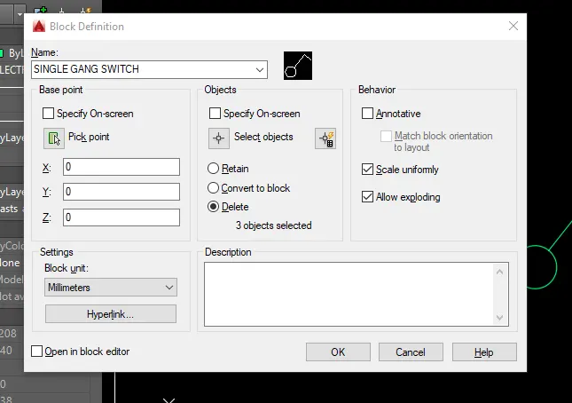
Command:BLOCKs
- Name the object as the name give in the drawing //SINGLE GANG SWITCH
- Select the base point. //select the center of the circle asbase point
- Select the object and click OK. //The object will now turn into BLOCK

//Repeat abve methods to draw every legends according to drawing given
STEP5
Command:INSERT
- select the name of the block u want to insert //small preview will be shown at the side
- check the specify on screen //To pu the block at your desired point freely
- check scale on screen and rotation. //To adjust the scale and rotation according to the space of column.
STEP6
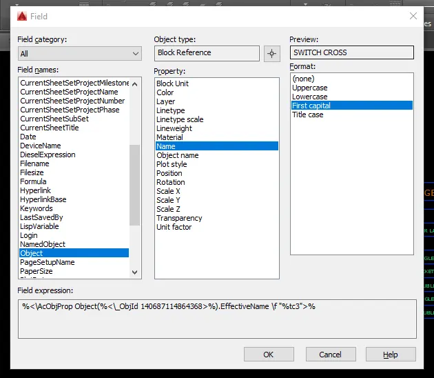
Command:FIELD
- select "objects" from field name
- Select objects . //select the object u want ot invoke the name
- Select name,click ok.
- paste the name at the place required.
//Follow the above mthod to insert the name and to make the legend table
RESULT:
4.
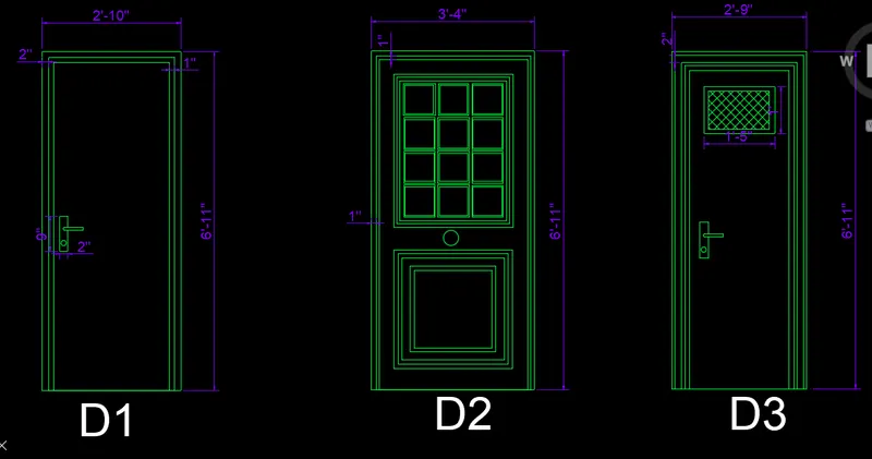
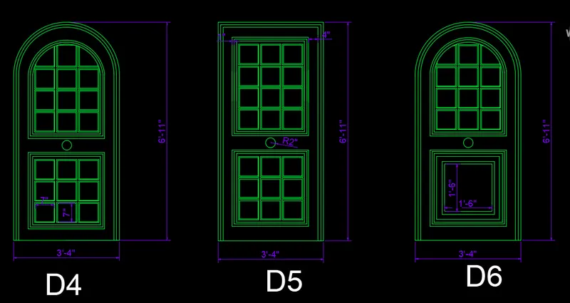
AIM:Create the door type for residential building as a block. Save the name of the blocks as type. Use given dimensions or assume dimensions as per industry standards.
PROCEDURE:
STEP1
Command:RECTANGLE
- click on a point for one corner
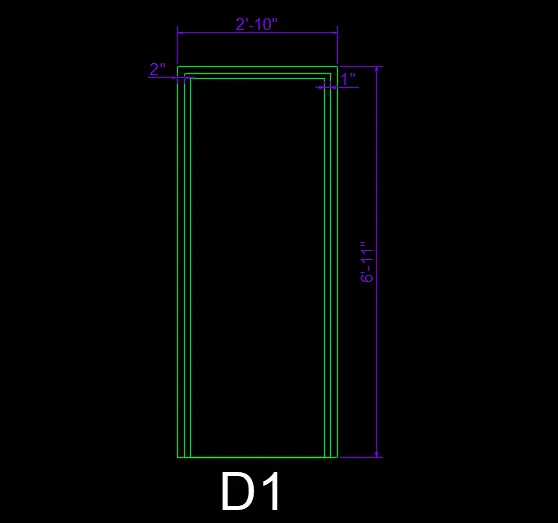
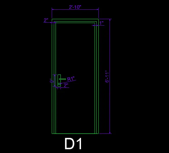
- create a rectangle of size 2'10" x 6'11"
Command:EXPLODE
- select the rectangle and click enter.
Command:OFFSET
- select the side of the rectangle and take offset of 2 inch //for the hinge part
- select the side of the hienge part and offset of 1" //to make width of the hinge
STEP2
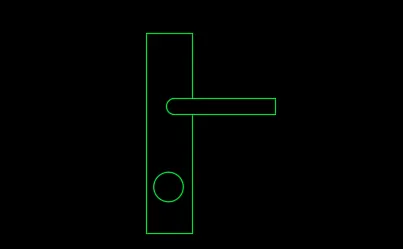
Command:RECTANGLE //To make the door handle
- make a rectangle of 2"x9" //To make the key part
- a rectangle of 4"x1" // to make the handle
Command:TRIM
- Trim the intersecting lines
Command:CIRCLE
- create a circle of 1" radius
STEP3
Command:RECTANGLE
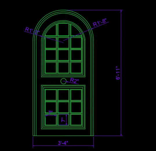
- create a rectangle of 3'4"x6'11"
Commadn:OFFSET
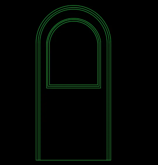
- from the abive line take an offset of 1'8" //for the outer arch
- from the above line horizontal take offset of 7" //for the inner arch
STEP4
Command:CIRCLE
- from the midpoint of line 1'8"offset,create a circle //the outer arch
- from the offset taken at 7",sraw the circle
Command:TRIM
- trim the extra intersecting lines
Commadn:OFFSET
- from the above arc take an offset of 1" //offset 2 times inwards
- from the smaller arc take an offset of are 1" //2 times inwards direction
STEP5
Command:RECTANGLE
- create a square of 2'5"x2'5"
- and create a 7"x7" square
Command :OFFSET
- select the square of 2'5"x2'5" and take offset of 1" inwards //To make door panel designs(take offset 2 times)
- select the 7"x7" square and take 1" offset inwards //For making the squaare panels
STEP6
Command:ARRAY
- Select the square 7"x7"
- enter the row and column R=3,C=3
Command:MOVE
- Move the ARRAy quare into the aquare of 2'5"x2'5"
//similarly move the square array to the above panel design //For the above design panel
Command:TRIM
- Trim the intersecting line of the panels designs
Command:CIRCLE
- Create a circle of 2" Radius into the middle of the door
STEP7
Command:BLOCKs
- Name the object as the name give in the drawing //D1 for the rectangle door D4 for the arched door
- Select the base point. //select the center of the circle asbase point
- Select the object and click OK. //The object will now turn into BLOCK
//Repeat the mthods as done above to make the objects in the drawing accoriding to the requirements of D2,D3,D5,D6
RESULT:
5.
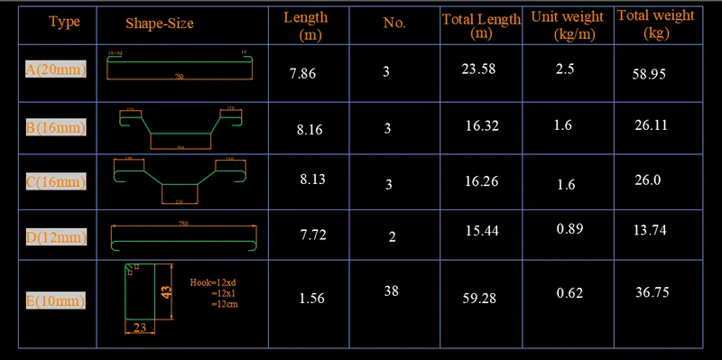
AIM:Create each shape as a block as shown in the Figure. Save the block and insert them on the table as shown in the Figure
PROCEDURE:
STEP1
Command:LINE
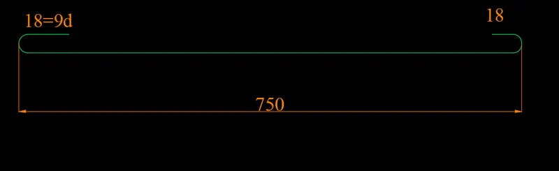
- make a line of 750mm //Main bar
- 10mm vertical and 18mm horizontal //Bent bar
Command:FILLET
- Enter the radius of 5mm
- select the first line and second
- CLick enter , //The corner line will be turned into fllet
STEP2
Command:MIRROR
- select the corner curve and bent bar
- select the base point //In the middle of the main bar
- and mirror it on the other side
Command:LAYER
- Create a new layer of name "bars" and choose a colour.
- create a layer of table and text and choose colour accordingly
- Select the bar and assign the layer properties to it //For assigning properties
STEP3
Command:BLOCKS
- name the blocks as A(20mm) //Giving name to the blocks
- Select the basepoint in the middle of bar
- select the object,click OK.
STEP4
Command :LINE
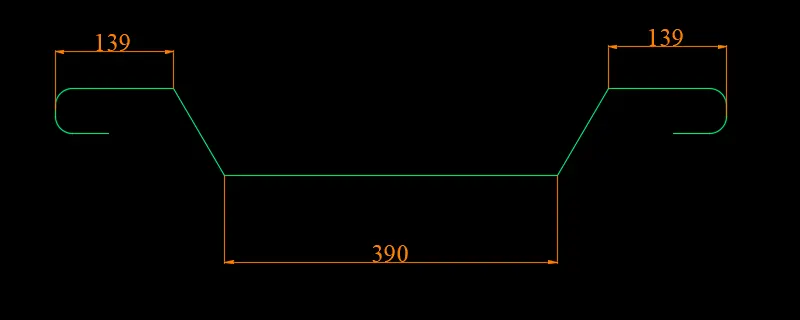
- click on a point draw 139mm line,71.4mm,390mm,139mm
- from the endpoint draw 10mm vertical line downwards //for bent-up bars
- Draw horizpntala 62mm
Command:MIRROR
- Select the bent uo bar and mirror it on the other side
Command :OFFSET
- select the 390mm line and offset it to 100mm down wards
Command:FILLET
- Enter the radius of 5mm
- select the first line and second (vertical line and main bar)
- CLick enter , //The corner line will be turned into fllet
STEP5
Command:ERASE
- erase the middle line of main bar and extra lines
Command:BLOCKS
- name the blocks as B(16mm) //Giving name to the blocks
- Select the basepoint in the middle of bar
- select the object,click OK.
STEP6
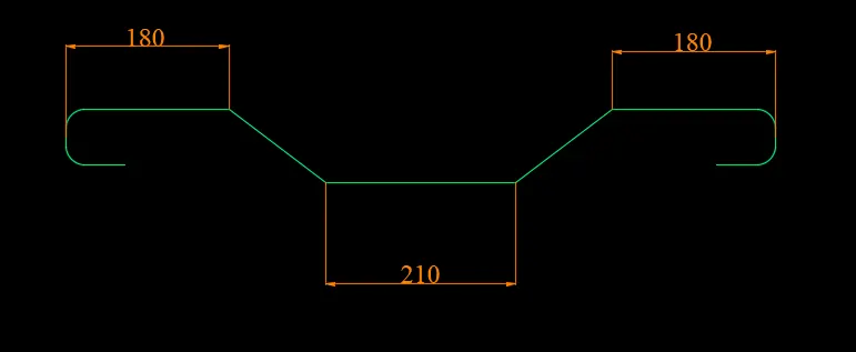
Command :LINE
- click on a point draw 180mm line,107.1mm,210mm,180mm
- from the endpoint draw 10mm vertical line downwards //for bent-up bars
- Draw horizpntala 66mm
Command:MIRROR
- Select the bent uo bar and mirror it on the other side
Command :OFFSET
- select the 210mm line(of the middle) and offset it to 100mm down wards
Command:FILLET
- Enter the radius of 5mm
- select the first line and second (vertical line and main bar)
- CLick enter , //The corner line will be turned into fllet
STEP7
Command:ERASE
- erase the middle portion line of main bar and extra lines
Command:BLOCKS
- name the blocks as C(16mm) //Giving name to the blocks
- Select the basepoint in the middle of bar
- select the object,click OK.
STEP8
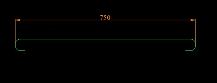
Command:LINE
- make a line of 750mm //Main bar
- 10mm vertical and 41.05mm horizontal //Bent bar
Command:FILLET
- Enter the radius of 5mm
- select the first line and second
- CLick enter , //The corner line will be turned into fllet
STEP9
Command:MIRROR
- select the corner curve and bent bar
- select the base point //In the middle of the main bar
- and mirror it on the other side
STEP10
Command:BLOCKS
- name the blocks as D(12mm) //Giving name to the blocks
- Select the basepoint in the middle of bar
- select the object,click OK.
STEP11
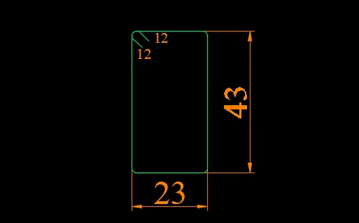
Command:RECTANGLE
- Create a rectangleof 23"x43"
Command:FILLET
- enter the radius 15mm //for showing the bent of column bar
- select polyline and select the rectangle //It'll give the fillet to all the corners
COmmand:LINE
- Type "Tan" for tangent from the circle //For taking a tangent
- draw a line on both the side of circle //TO show the bent up bars of stirrups
- the line should be of length 12mm
STEP12
Command:BLOCKS
- name the blocks as E(10mm) //Giving name to the blocks
- Select the basepoint in the middle of bar
- select the object,click OK.
STEP12
COmmand:RECTANGLE
- Create a rectangle of appropriate size //Big enough to adjust the size of the bar bendinsgs
Command:XPLODE
- Explode the rectangle //so that the lines can be used to mak row and columns
STEP13
Command:OFFSET
- enter "t" for through
- select the lines and move freely uptop the widht and depth of column rows required.
Command:TEXT
- click on heading place to type the texts //example-name,shape-size,unit weight etc.
STEP14
Command:INSERT
- select the name of the block u want to insert //small preview will be shown at the side
- check the specify on screen //To pu the block at your desired point freely
- check scale on screen and rotation.
//Insert all the blocks in the space given in the table
Command:FIELD
- select "objects" from field name
- Select objects . //select the object u want ot invoke the name
- Select name,click ok.
- paste the name at the place required.
//Place all the name of bar bending in th respecting rows
RESULT: