To plan a structural layout and to create grids using TSD
1.
AIM: Summarize the user interface in TSD with the for the following items: -
- Project Workspace – How to access and usage
- Scene Content – Demonstrate the use of scene content
- Create two scene views
- Loading drop list- How to access
- Properties windows – how to access and usage
SOLUTION:
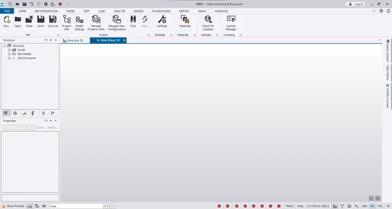
- 1.project workspace is the interface where you get to work on your file or projects.
- Open Tekla structural ->click on new
- The new opened space is called the projects workspace.
- It has useful features as model-> to model new structure components,Analyse ,design etc.
- 2.Scene content
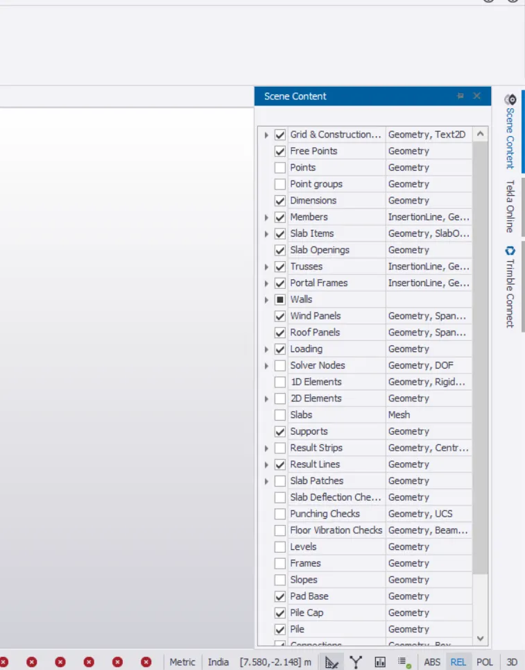
- As you open a new project you can go to windows->scene content
- or at the right most of the screen you can access the scene content
- it is used to enable or disable the visibility of objects,dimensions colours etc.
- Uncheck the boxes which you don't wanna see on the screen.
- 3.Create two scene views
- on opening the new file tekla automatically makes 2 views of the file
- 2D and 3D view
- to show the 2 views perspective I have drawn a grid line to show both type of view.
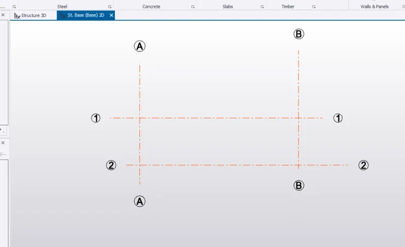 //2D view
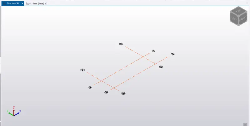 //3D view
- 4.Loading drop list-how to access.
- drop list are seen on the panel on the left side of the screen
- On the botton side click on the loading section->loading list wil open
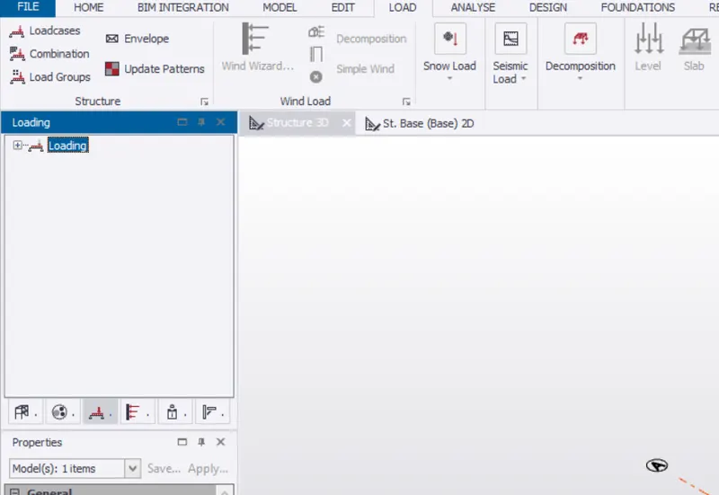
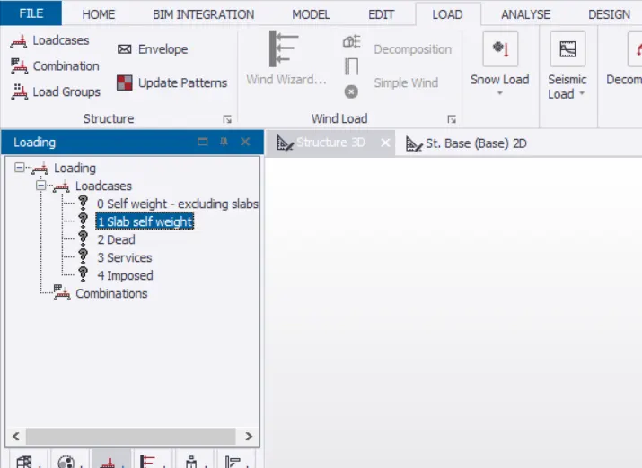
- Now click on the+ icon to drop the lists
- select the list which you want the loading to assign.
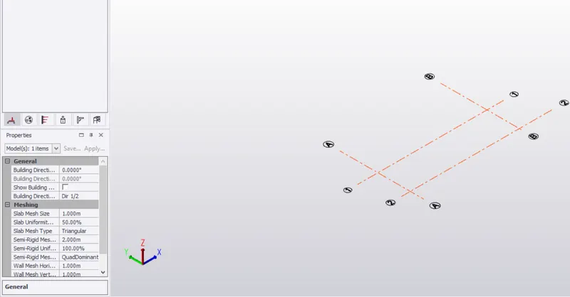
- 5. Properties windows – how to access and usage
- to open or close properties windows->go to windows panel ->activate properties windows
- then below left will be the properties windows shown
- this window shows the properties of any element or objects you select.
2.
AIM: Create a new file in TSD and set up the settings for a steel building to have member grade FE410 and concrete grade of M30 as per IS codes. The covers for the members to be as per the following input: -
|
MEMBERS |
IN CONTACT WITH GROUND |
ABOVE GROUND |
|
Column |
50mm |
40mm |
|
Slab |
30mm |
25mm |
|
Pile cap |
75mm |
|
|
Foundation |
50mm |
SOLUTION:
- OPen the Tekla structural ->create new file
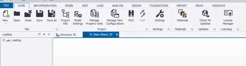
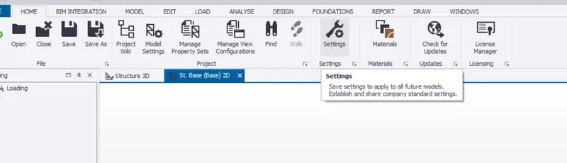
- Go to Home tab->click on materials ->a new tab will open
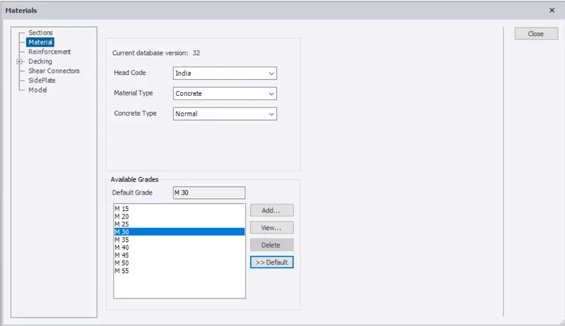
- Go to material section->select material type->select M30 grade->click on default
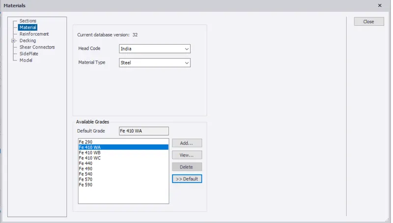
- Now change he material type to Steel->select FE410 as per the requirements
- set as defaults.
- Now to provide the clear cover to the materials
- Go to home tab->click on settings->a new tab opens
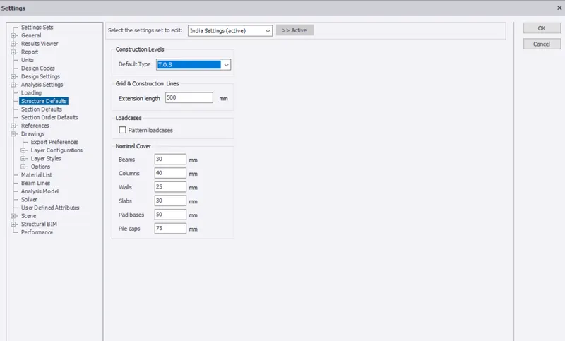
- Change the default type to S.S.L(structure slab level) and enter the value of cover in contact with the ground
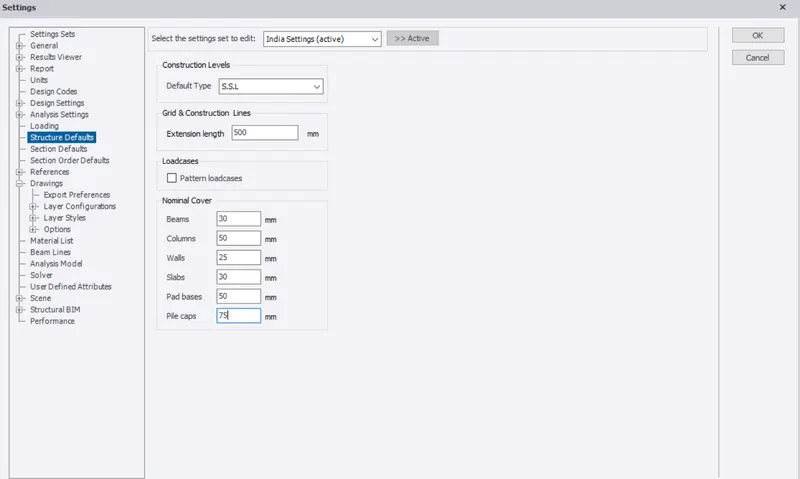
- Now change the Default type to T.O.F( top of foundation) and enter the cover values above the ground
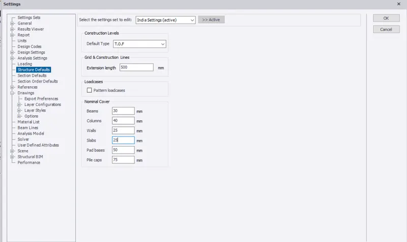
3.
AIM: With reference to the input drawing as per Attachment 1, 1.1, and 1.2 and study the steel building plan and summarize your understanding of the plan. Based on your study assume and explain the location of columns and beam and develop a hand sketch for each plan.
SOLUTION:
- Based on our studies columns are not to be placed at the openings i.e. doors,windows etc.
- columns should not be placed on the property lines.
- centre to centre distance between columns shouldd not be too much.
- columns are to be placed at the intersection of the beam and walls.
- columns to be placed in such a way that it doesn't foreshadow the aesthetic of the interiors.
- GROUND FLOOR
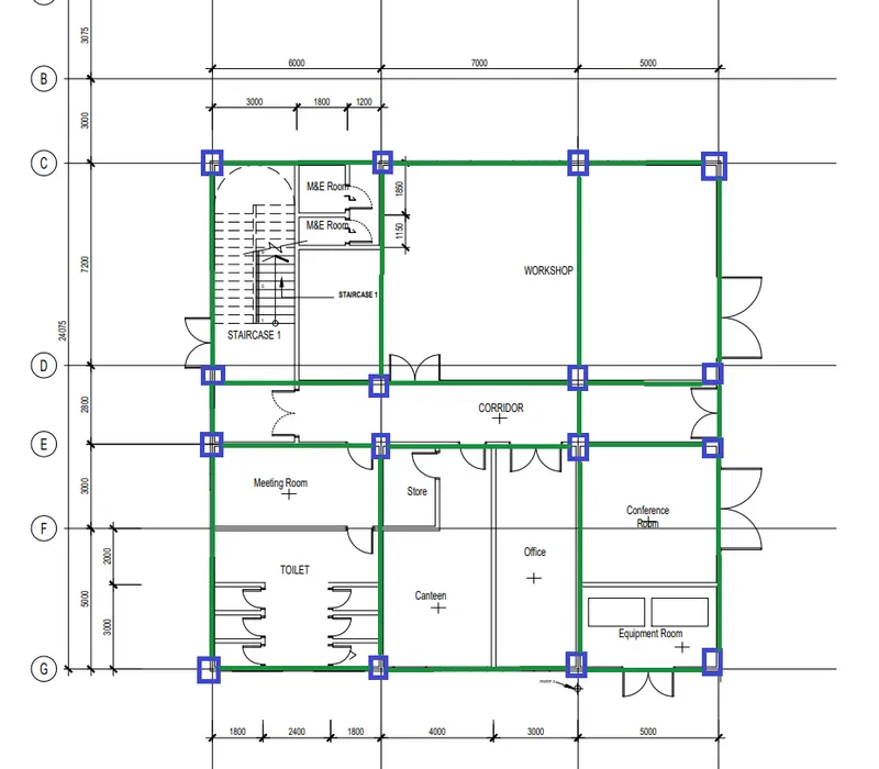
- FIRST FLOOR
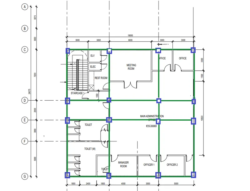
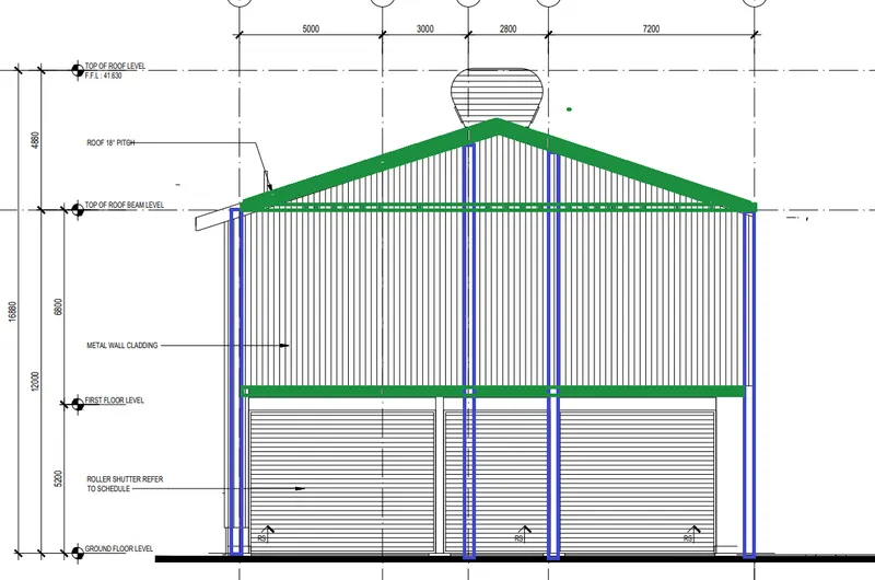
- ELEVATION:
- The lines in green are the beams
- the blue lines are the columns
4.
AIM: Model grid lines and construction levels as per Attachment 1. 1.1 and 1.2. All dimensions are in mm
- The base level to be 500mm below ground level.
PROCEDURE:
- Open Tekla structural->click on new file->Project workspace will open
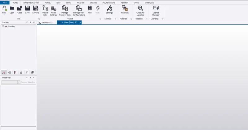
- Go to model tab->construction levels
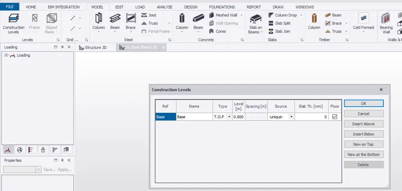
- a new tab will open->here input the levels you want
- Enter the height levels as per the Attachment files 2,2.1
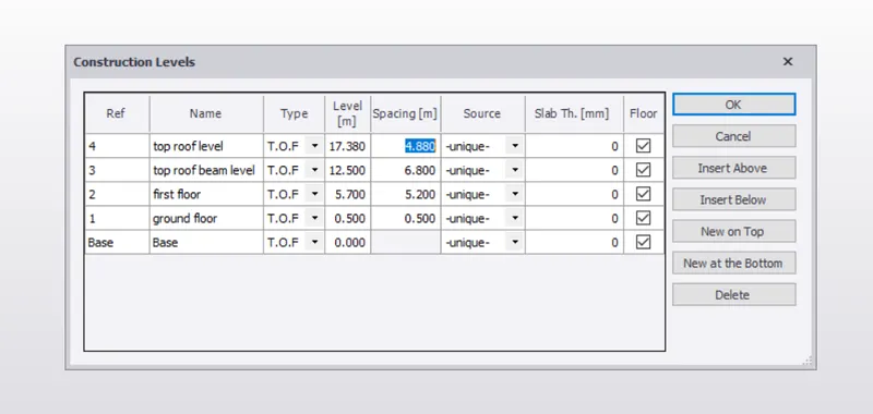
- Now after creating the levels ->click on OK
- Now go to the structure panel->select any base floor level
- Go to model tab->grid lines->create the grids according to the floor plan
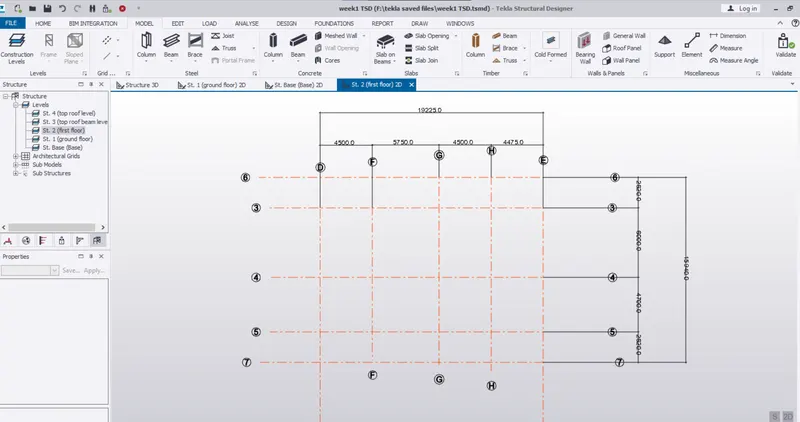
- RESULT:
- The construction level grids are drawn according to the Given attachment 2.1