Reinforcement Detailing of Beams from ETABS output
QUESTION:
Detail design of beams in Etabs 2018.
The ETABS file for a G+4 building is provided. Run the analysis and design the RCC Moment ResistingFrame. The following challenge deals specifically with two continuous beams in the 1st floor.
1) 3 span continuous beam along grid A
2) 7 span continuous beam along grid 3
Address the following issues thereafter.
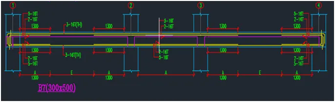
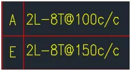
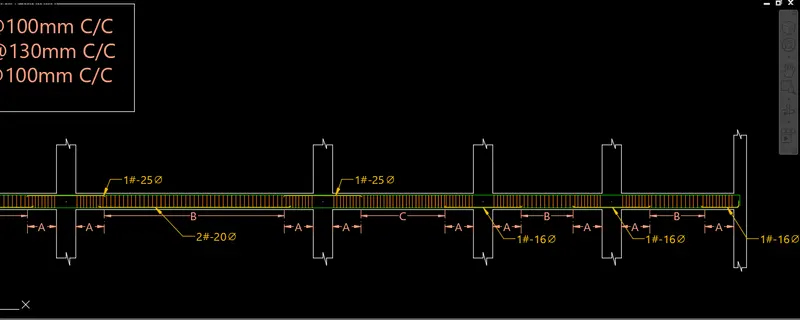
• Provide details of longitudinal and shear reinforcement for the two continuous beams. Sketch the beam elevation details or draft it using autocad software. A sample of how beam elevation details is prepared in consultancy firms is provided below. Participants can prepare it as per their preference:
• Provide reasons for failure of the middle span along grid A. What are the possible ways this issue can be resolved?
• Calculate value of the maximum shear force in any one of the spans in both the continuous beams, as per clause 6.3.3 (b) in IS 13920 – 2016. Also, confirm these values from shear force demand calculated by ETABS.Please note that if longitudinal reinforcement provided is more than required (as per ETABS results), the shear force demand will vary from what is provided by ETABS
PROCEDURE:
STEP1
- after downloding the attachment file week 7 ->open the file in ETABS 2018
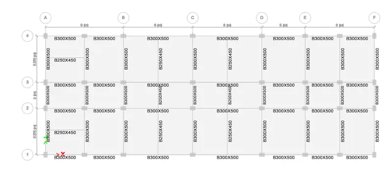
- the structure will look as shown below
STEP2
- next we check design combination
- go to concrete frame design->design load combinations
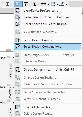
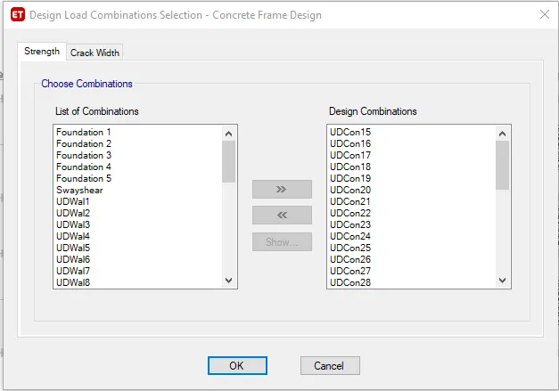
- click OK
STEP3
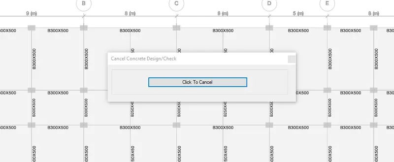
- Run the analysis
- concrete frame dsign->start design/check
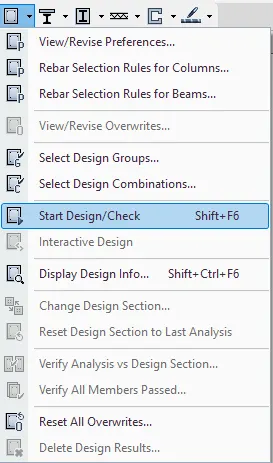
STEP4
- after design of beams we have to see the design information
- Go to concrete frame dsign->display design info
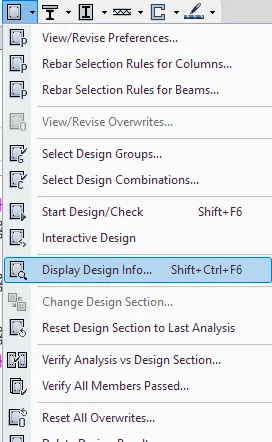
- a new tab will open
- select display output->longitudnal reinforcement(to show the output of longitudnal reinforcement)
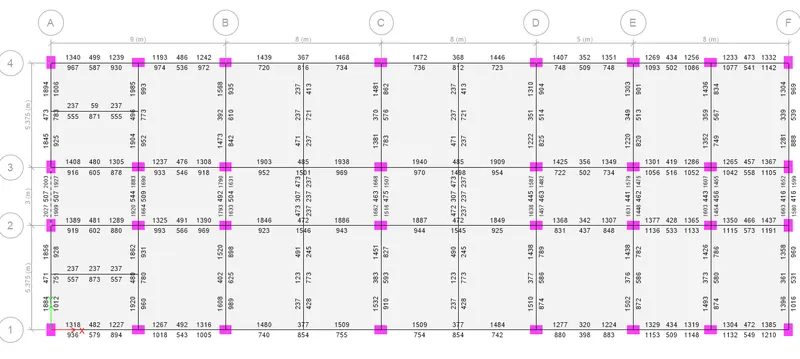
- the structure with reinforcement detail will be shown
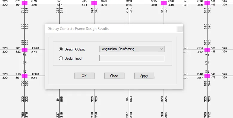
Shear along grid A
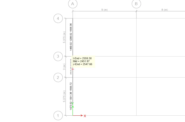
STEP5
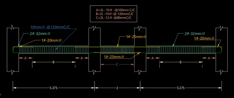
- Now reinforcing detailing is done along Grid-A of 3 continous beam span at of first floor
- maximum Ast at bottom is 1927mm^2 and at middle bottom is 783mm^2
- Maximum Ast at top 2027mm^2 and at the middle is 507mm^2
- from keeping in mind Ast of 1012mm^2 we provide 2# bars of 32mm Φ=1608mm^2 along the full length at the bottom face of beam
- 1 additional bar of 25mm Φ=490mm^2 to satisfy the requirement at the middle bottom section(A 2-3) of beam
- similarly 2# of 32mm Φ bars=1608mm^2 at the top face of beam along full length
- Additional 1#-1# bar of 20mm Φ=314mm^2 provided at both ends of continous beam on top face i.e. at 1A and 4A
- additional 1# of 25mm Φ=490mm^2 provided at the middle of the beam top face .i.e 2A-3A
We calculate shear reinforcement by formula:
=(1000*No. of legs*area of steel)/Spacing
- The result we get from the above formula must be greater than the shear values we have in the beams
- To get variation of shear values you can change in the size of diameter or spacing between the stirrups.
- the shear designing case is shown in the box below.
STEP6
- Now we design longitudnal reinforcement for the span of Grid-3 having 7 continous beam
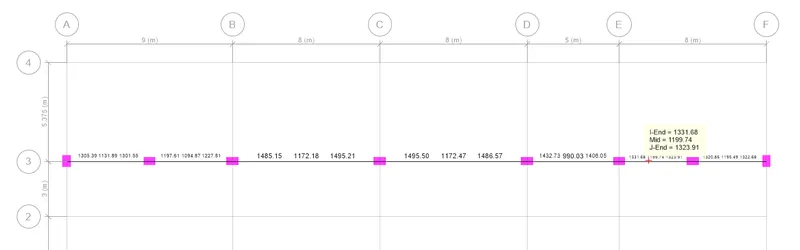
- maximum Ast at top is 1940mm^2 and at top middle is 485mm^2
- MAximum Astat bottom is 1105mm^2 and at middle bottom is 1501mm^2
- considering 1308mm^2 from the top face we design the reinforcement 2#-32mmΦ =1608mm^2 along full length
- 1 Additional bar of 25mmΦ=490mm^2 each at the top face B,C,D beam column intersection
- Now for the bottom face 2#-25mmΦ used along full length
- Additional bar of 2#-20mmΦ between B to C and C to D each and 1#-16mmΦ=201mm^2 to satify the need each at the columns between E to F
Shear along grid 3
We calculate shear reinforcement by formula:
=(1000*No. of legs*area of steel)/Spacing
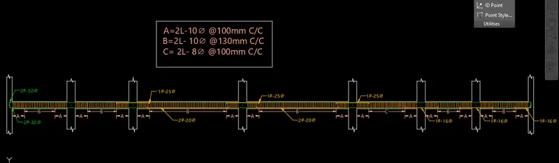
Left side beams
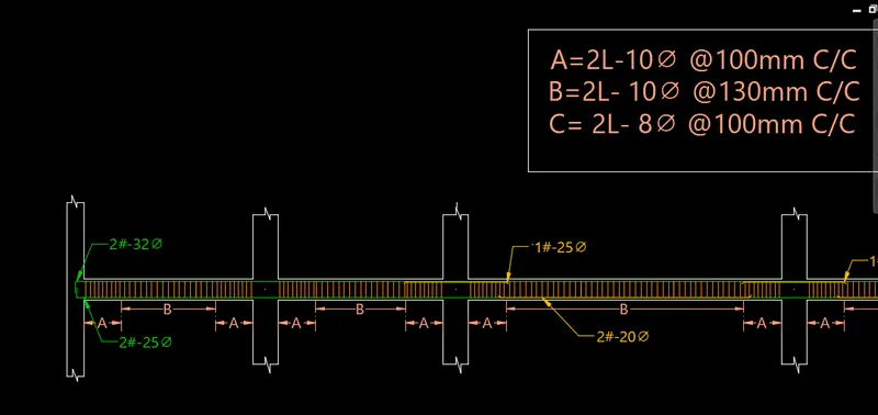
Right side
STEP7
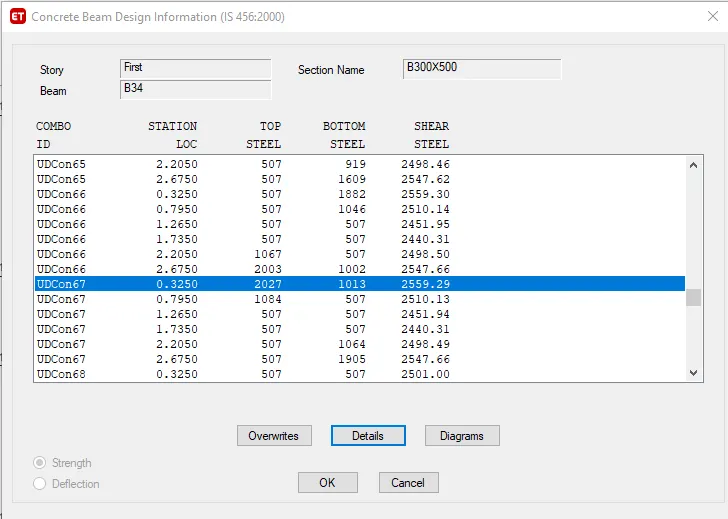
- Now right click on the mid span beam along grid 3,( B34)
- A new tab will open->click on details->shear details
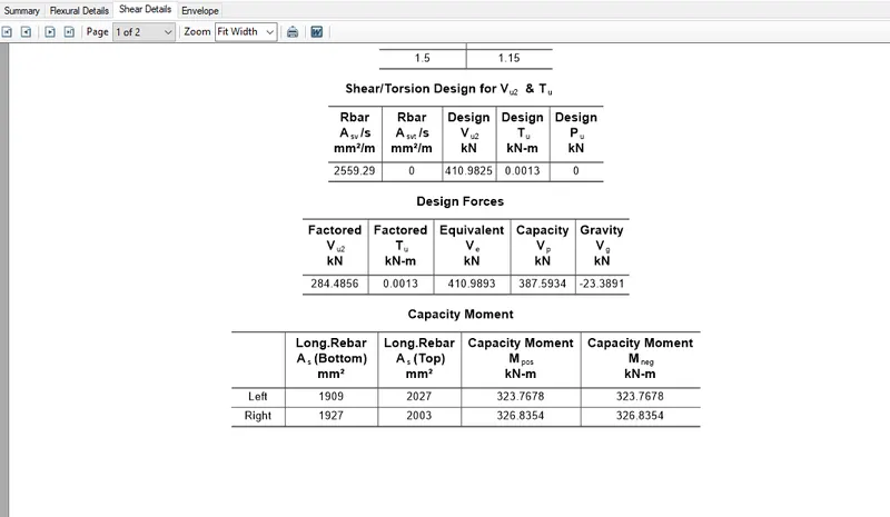
- As per IS13920 clause 6.3.3 the force of equivalent Ve=410.98KN
- shear force under linear analysis as per load combination UDCon67 ,Vu2 =284.48KN as calculated by ETABS
- as you can see the factored shear is less than the Equivalent therefore the beam is safe frim shear
Reason for failure and solution:The reason for the failure of beam alogn mid span of grid A is due to the etreme shear stress,this can be resolved ny reducing the beam depth which in turn reduces the requirement of stiffness and caues the decrese in shear stress in a beam.