Structural Modelling using Etabs 2018
AIM:
The architectural drawings for a G+7 residential building in zone 5 has been provided. The floor plan is the same for all 7 floor levels. Possible column positions have also been provided. Conceptualize a framing plan layout and then model the building in Etabs. The following architectural drawings have been provided:
- Typical floor plan – The location and thickness of the brick walls and the use of the
space (for estimating live load) can be obtained from this plan - A building section through the staircase and lift core is provided
- Parking layout in the ground floor – the column/shear wall arrangement must not
obstruct entry/exit of vehicles.
The following loadings are to be taken into account: - Brickwall made of AAC blocks
- Finishes – floor tiles of 75 mm thickness
- Live loads as per IS 875 part 2
- Water tank of 20 KL above the staircase at Mumty level
- Lift Machine room at mumty level above lift core
The structural model must comply with provisions of IS 1893 and IS 13920.
Run a modal response spectrum analysis and check analysis results of the etabs model for inter-storey drift requirements, vertical & planar irregularities, minimum shear wall requirements,maximum axial load ratio for column and shear walls, effective moment of inertia for beams
and columns etc.
PROCEDURE:
STEP1
- Open Etabs
- Create new file->use built in settings
- A new tab will open->select user grid system(use spacing)
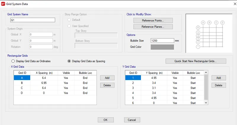
- Click OK
STEP2
- Now go to user defined floor system->enter the no. of floors you want
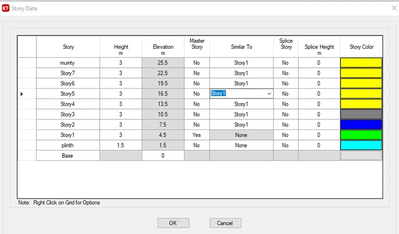
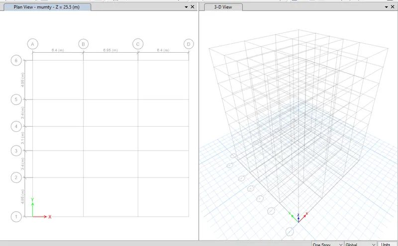
- CLick on OK->Now the grid system will be visible.
STEP3
- Now go to define->material properties
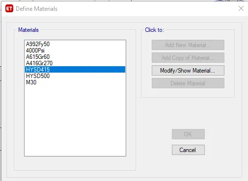
- Click on add new materials to add HYSD500,HYSD415,M30
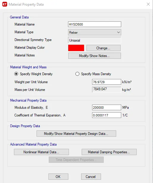 //similarly add 415 and M30
STEP4
- after adding material properties->we add beam and column sizes
- Go to define->section properties->select rectangular section
- Add new property->a new tab will open->enter the name C400x500
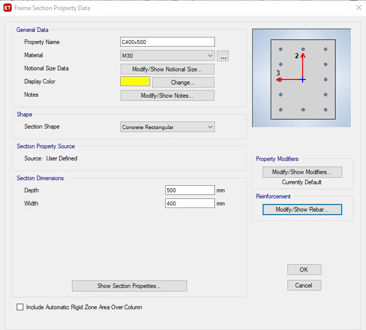
- Click on add new material->enter the B300x500
- enter the types of rebars
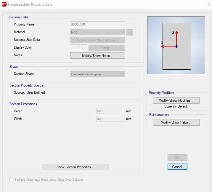
- Similarly add different sizeof columns
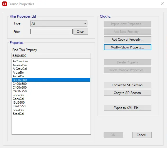
STEP5
- Now we add slabs and walls
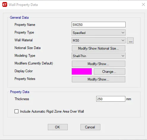
- go to Define->section property->walls section
- Add new property->enter the name SW250
- wall material as M30->enter the thickness of wall
STEP6
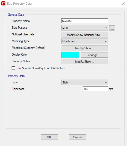
- Now we add Slabs->define->section property
- slab section->add new proprty->enter the name of slab->enter the thickness
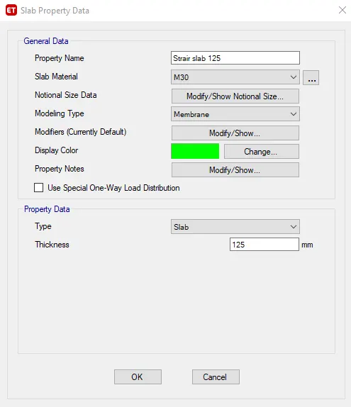
//Similaryly do for the stair slabs with thickness 125 (Tick the special one way load distribution for stairs slab)
STEP7
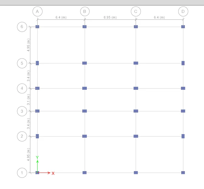
- NOw we have to add columns and beams
- Click on quick draw columns-
STEP8
- Now similarly->select quick draw beams->select the beam type(B300x500)
- select all the frames and the beam will be applied to all floors
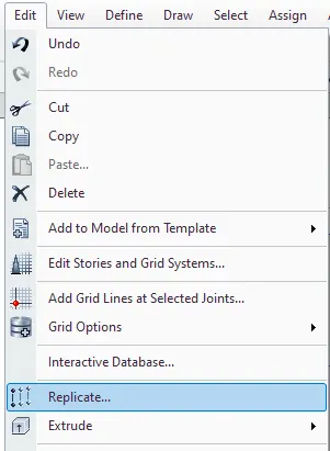
- Go to edit->Replicate(to replicatebeams at a distance)->a new tab appears
- enter the distance in dx or dy you want
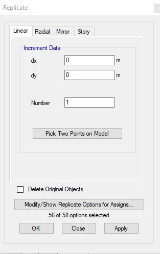
- Use the values to replicate at distance of different beams to achieve the design.
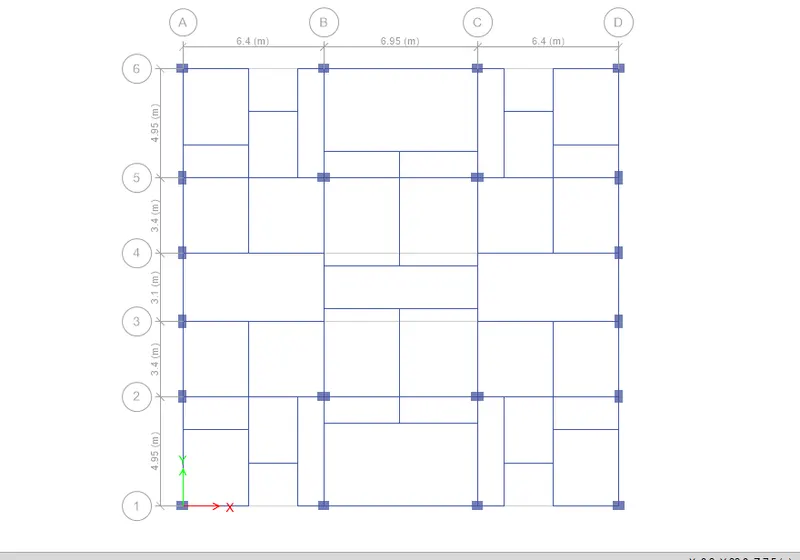
- Go to base plan->select the columns (change slection to one story)
- Go to assign->joints->restraints(Add fixed support)
STEP9
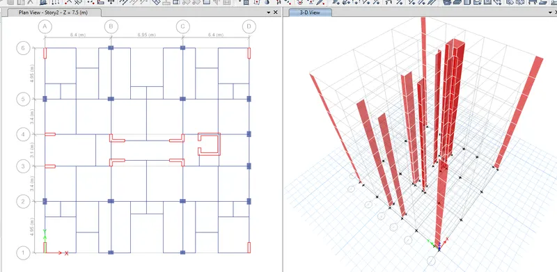
- Now we add shear walls to the structure
Note-"We remove the column where the shear walls are added"
- change the selection to all stories->select quick draw walls->select the SW250 frame rpoperty
- Apply walls at the parts required in the builidng as per your calculation
- Make sure not to obstruct the parking way of cars and not disturb the architectural design
STEP10
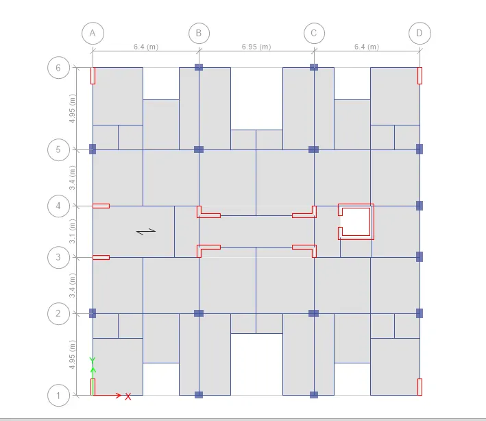
- Now we apply slabs->Go to quick draw slabs/floors
- select the slab150 and select the slab areas you want
- The slabs wiil be applied to all the floors
STEP11
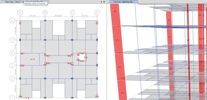
- Now we label the the piers -.>Assign->shell->pier labels
- select the shear walls and assing the pier labels individually
STEP12
- Now we enter the load patterns
- Define->load patterns->a new tab appears
- input the live ,dead ,brickwall,and seismic loads
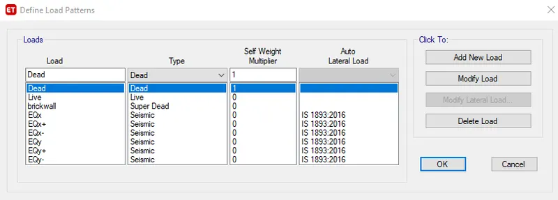
- CLick on EQ and modify lateral load
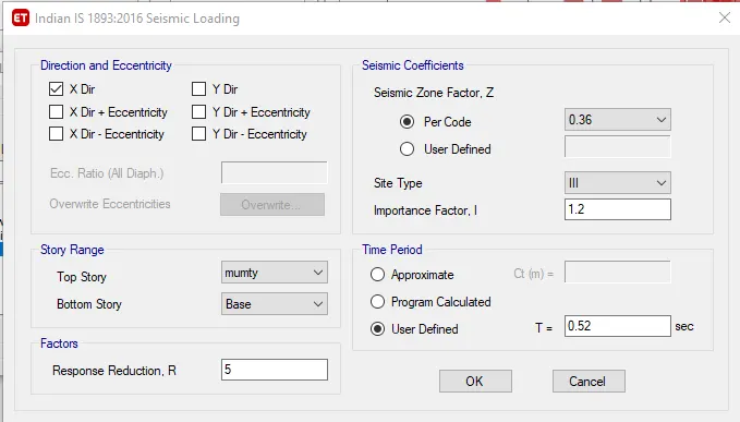
//For EQ loads ,modify the lateral loads ,Given Calculated time period Ta=0.52 (calculated as per IS 1893 part1 7.6.2) by Ta=0.09*h/d^(1/2)
//Importance factor is 1.2
STEP13
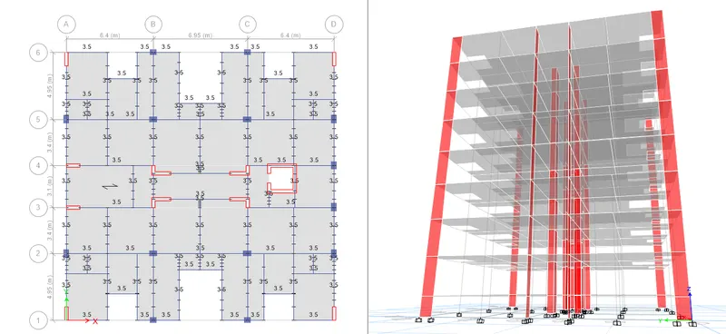
- Next we apply the loads on the frames
- Select->object types->beams(keep selection to all stories)
- Go to Assign->Frame load->distributed load
- a new tab appears->select brickwall->apply load of 3.5KN
STEP14
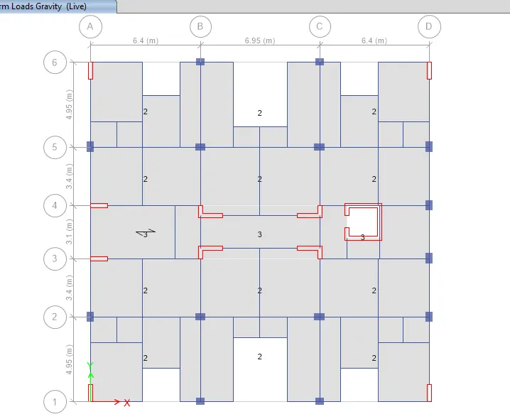
- Next we apply live loads on slabs
- Select->object types->floors
- Assign->shell loads->uniform loads->select live and input 3KN for stairs slab,walking path and elevator slabs
- //Similarly apply live load of 2KN on the Remaining slabs
STEP15
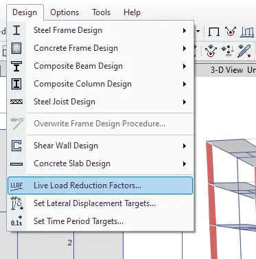
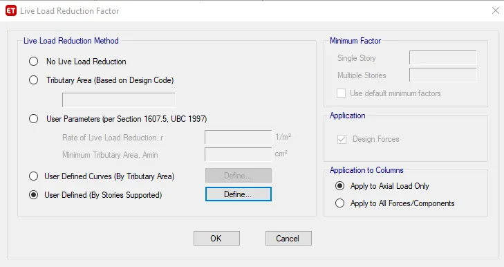
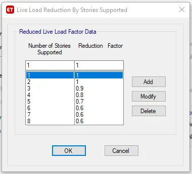
- Next we have to apply live load reduction factor
- Design->Live load reduction factor->a new tab will open
- CLick on User defined to define by yourself-> add the reduction factor according to IS 875 part2 3.2.1
STEP16
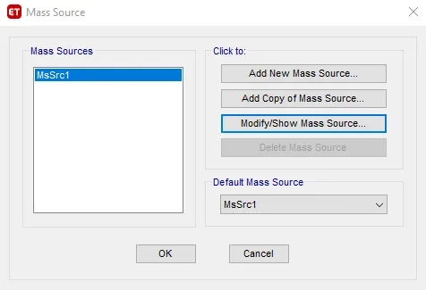
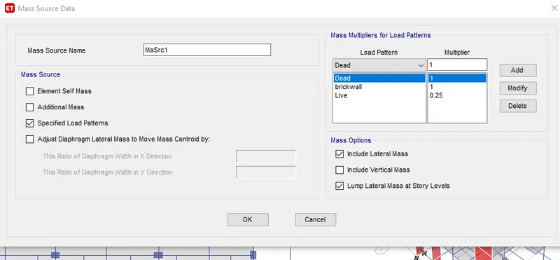
- Now we add mass source->Go to define->mass source
- click on modify mass source->a new tab will open(give live load of 25% when the live load on floor is greater than or equal to 3KN)
STEP17
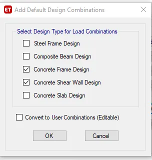
- Now we define load combination->define->load combination
- click on add default design combo->select concrete fram design & concrete shear wall designs (Editable)
- Now we add the diaphragm
- Select->Object types->floors
- Assign->Shell->Diaphragm(a new tab opens)
- select D1 and click OK
STEP18
- NOw go to define->modal cases->go to modify case
- increase the number to 30 modal cases
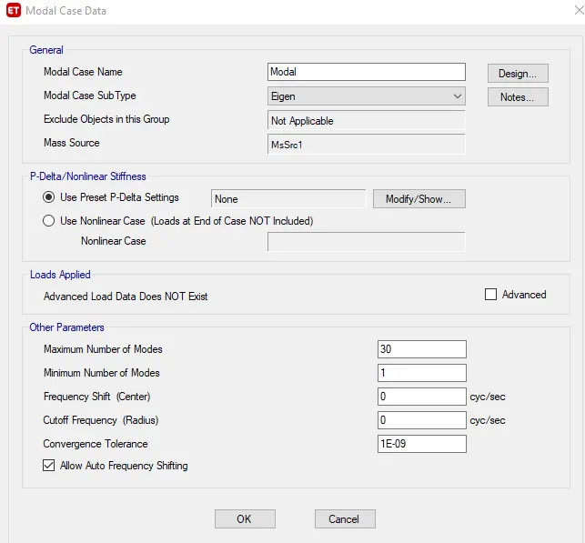
- Now we check the modal
- Go to analyse->check modal
- A message will be shown with check results(if any error occurs it'll be shown)

STEP19
- NOw we add response spectrum
- Define->fucntion->response spectrum //A new tab will open
- VHange the code to IS 1893:2016->Add new function->name it as "IS FUNCTION" and remainign data will be set automatically
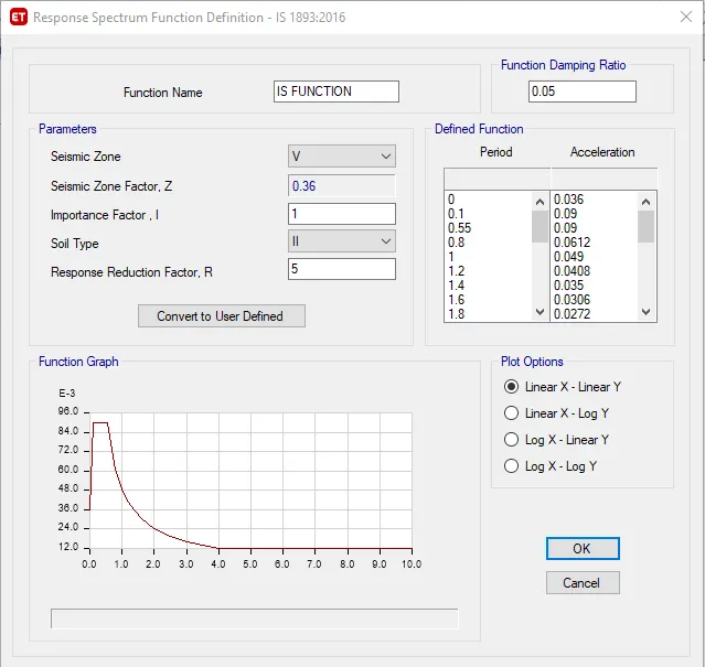
- Next we apply load cases
- Define->load cases->add new case ,a new tab opens
- Name it as RSx->load case type as "Response spectrum"->CLick OK
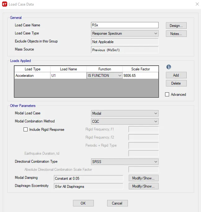 //Similarly we add new case for RXy with Load name as U2
STEP20
- Now we have to run the analysis->Analyze->run analysis
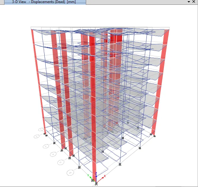
STEP21
- After the analysis is done ->show tables->modal participation mass ratio & base reactions
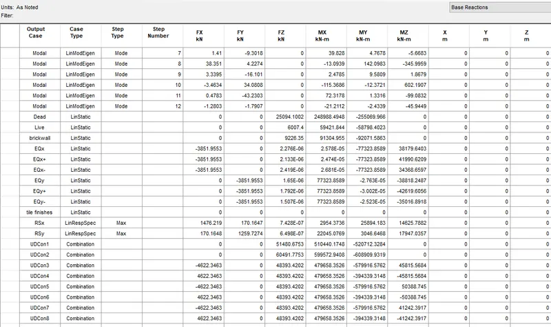
- For the structure to be stable the response spectrum (RSx & RSy) must be nearly same as of Seismic forces (EQx & EQy)
- For response spectrum to be equal we use a formula [(EQ/RS)*Scale factor],The scale factor here is 9806.65 we got in load case data
- [(3851.9553/1476.219)*9806.65]=25588.87 for RSx
- for RSy=29986.47
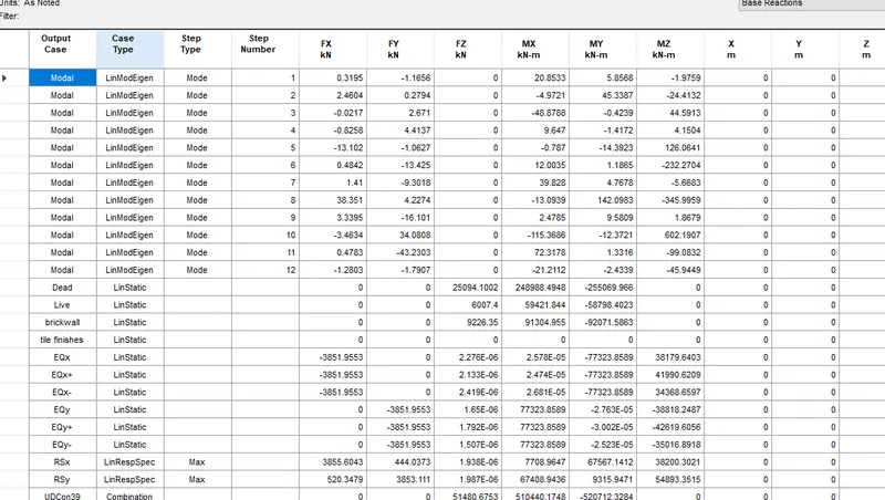
- he obtained data is then replaced by the scale factor(9806.65) which gets us the value of RS closer to EQ.The resultant BAse raction table will be as shown
STEP22
- Go to display->show tables->modal participating mass ratio
- The table shown below
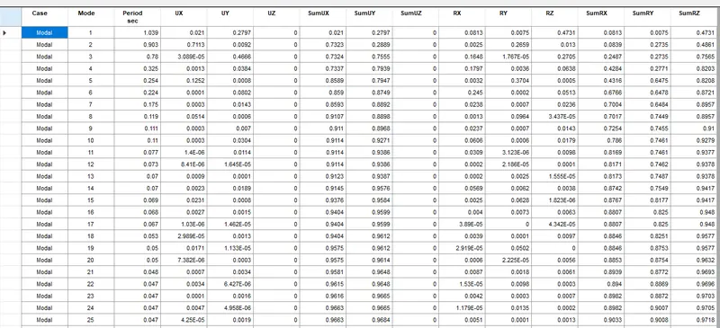
- The natural time period of Building is around 1.039sec which is acceptable for a 7 storey builidng(nearly 0.89sec for 5-10 storey)
- A Minimum of 25 mode needed in this case as we achieve 90% value for RX in 25 mode
STEP23
- now to check the max storey drift
- Display->storey response plot->Display type->Max storey drift->Case as EQx
- It's safe as the max drift less than is 0.004
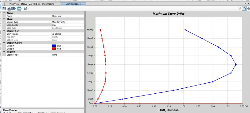
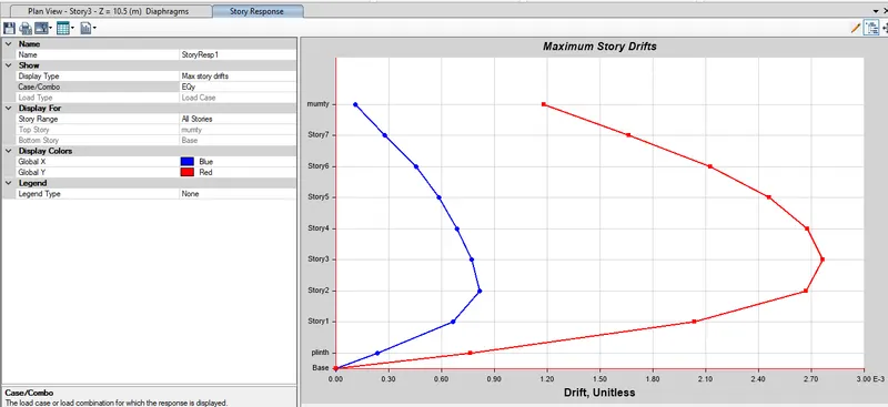
- storey response plot->Display type->Max storey drift->Case as EQy
- Drift along Y direction is also safe
RESULT:The analysis is done and the proper proper design shear walls are also given successfully