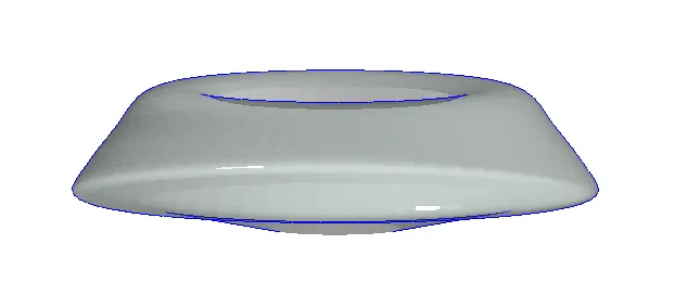
Creating Conceptual mass in REVIT and Creation of Sinusoidal curve and a Parametric stadium using Dynamo
1.
AIM:Using Dynamo create a set of sinusoidal points and create a curve and create a surface out of the curve.
PROCEDURE:
- OPen revit->New Architectural template
- MAnage tab->Dynamo
- On Dynamo->New
STEP1
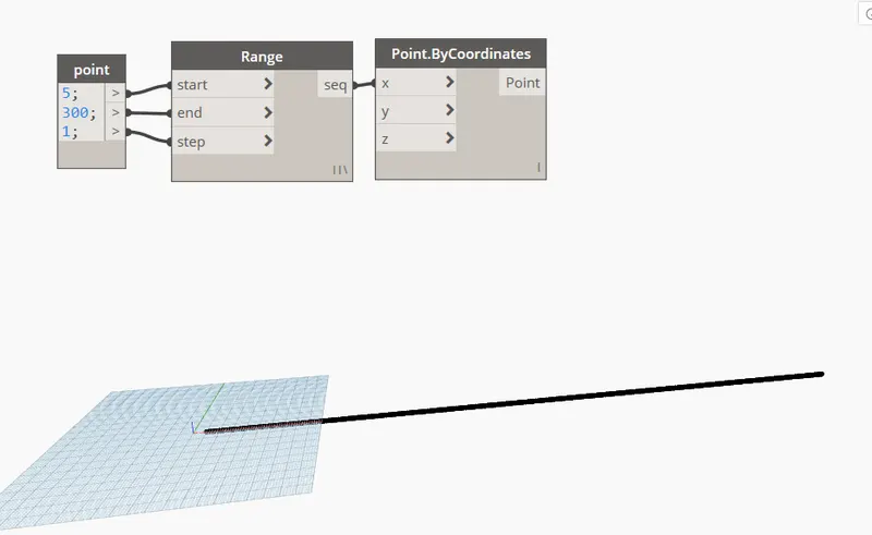
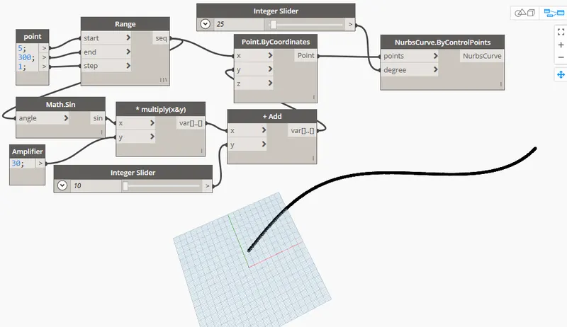
- IN search tab->"Code block"->Enter value of start,end,steps;
- Search "Range"->Project the values in the range;
- Search "Point.Bycordinates"->Project the range value in X //SO that the point lines goes in X axis
STEP2
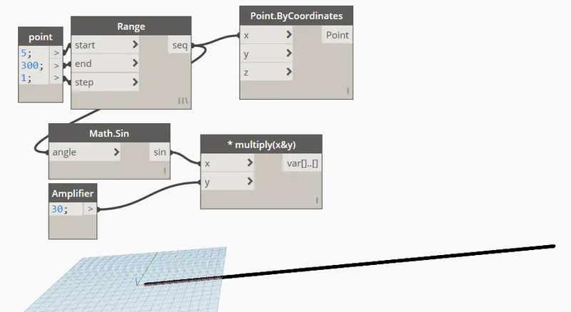
- Search "Math.sin" and insert in dynamo
- Add code block and rename it as "Amplifier"->Enter value of 30
- Now direct the sequence of "Range" into "Math.sin".
- open a "Multiply" node->Project the Sin value in X and Amplifier into Y of the "Multiply" //It'll create the sinusoidal wave
STEP3
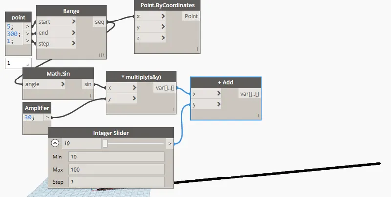
- Enter a node "ADD" to add the Sin wave and the direction
- Enter a "Integer slider"->enter minimum value of 10
- Project the variable of Multiply to "X" and Integer slider to "Y" of ADD node
STEP4
- Project the variale of ADD node to "Y" of Point.Bycordinates //To create the wave in Y direction,Put in Z if u want in Z direction
- Create Integer slider->Put minimum value of 20
- Create a Nurbescurve.bycontrolpoint (which takes points and degree)
- Project the Point of coordinates in POINTS and integer slider in DEGREE of Nurbescurves
STEP5
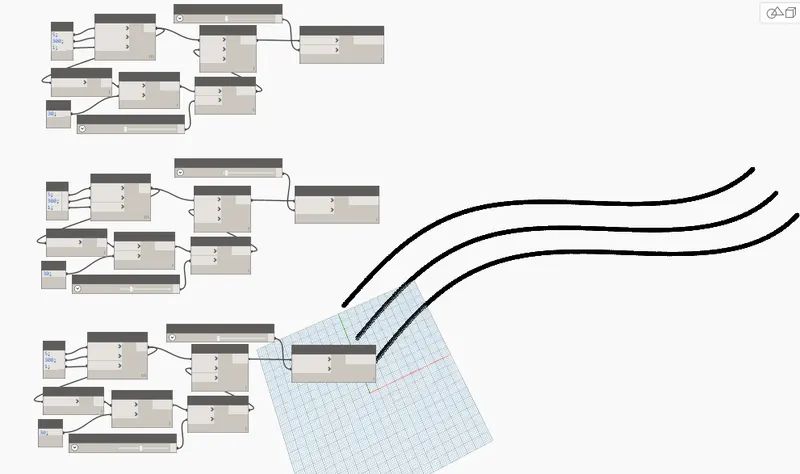
- Copy and paste the nodes 3 times for 3 waves //Paste it as much waves u need
- Increase the Integer slider in the other 2 copied nodes //To move the other two waves apart at some distance ex. 20 and 30
STEP6
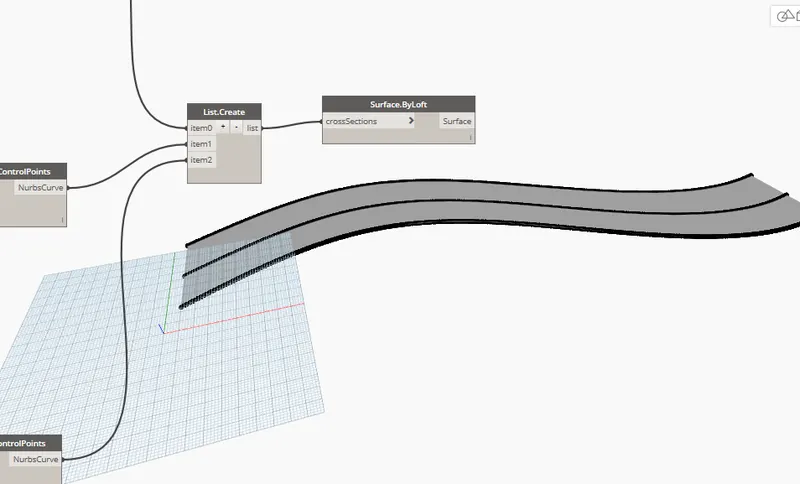
- "List.create" node->project the Nurbscurve of the above copied
- Projectt the nurbscurve to each item of the list
- Create "surface.Byloft"->project the list into the Crossections.
RESULT:
2.
AIM: Create a conceptual layout of floor plan in dynamo . Using the tools available in dynamo link the lines to appropriate model elements in Revit by choosing the wall types and wall parameters. Make use of the sliders to slide through the height of the wall and length of the wall.
PROCEDUERE:
STEP1
- Open revit->New Architectural template.
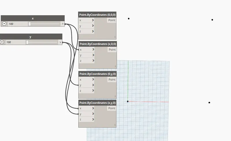
- Open Dyanmo->Create 2 "Integer slider"->Give minimum value of 100
- Rename them as X&Y
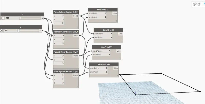
- Create 4 "Points.ByCordinate" And name them //For origin(0,0,0),X(x,0,0)point ,Y(0,y,0) point xy(x,y,0) point
- Project the X Slider on Point having x coridnate and Y slider on Y cordinate
STEP2
- Create 4"line.Bystartpointendpoint" for each point to connect
- There by project the points created in above steps to the lines of (OtoX),(OtoY)(XtoXY)(YtoXY) start to endpoint
STEP3
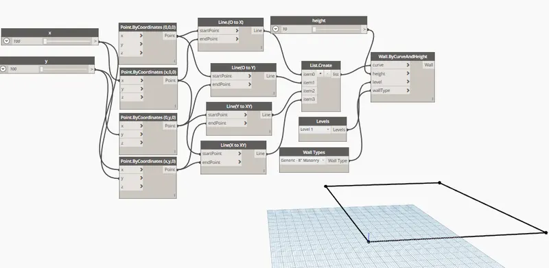
- "List.create" to create a surface for the wall->Add items to each line i.e. 4 items
- Create node "walls.bycurvesandheight"->It takes input of height,levels,walltypes and curves
- Numberslider for height of wall->Minimum height of 10
- "Levels" gives the level you want in the dynamo
- "Walltypes" and curves take the values from the list
STEP4
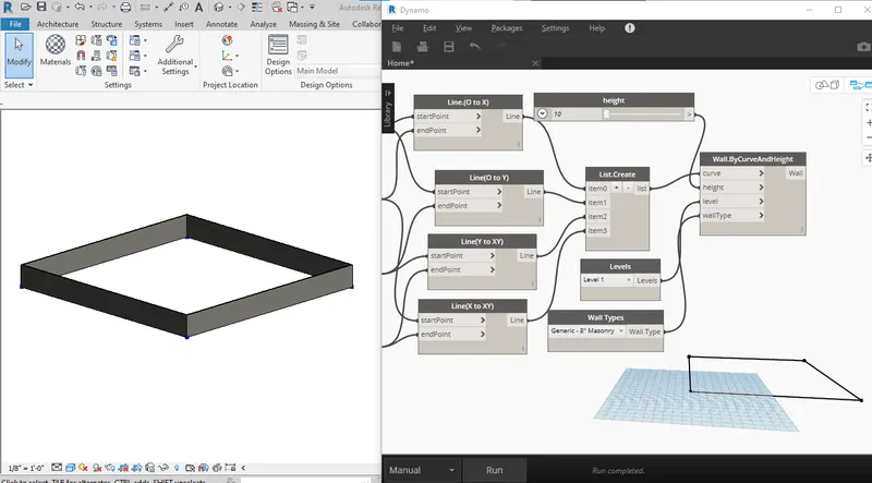
- No go to revit page->Minimize dynamo and keep it side by side with revit
- Go to 3d view in revit
- In dynamo->Increase the Height slider of the wall->It'll reflect he changes in realtime in revit
RESULT:
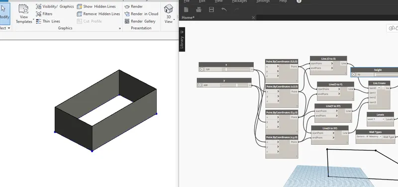
- increase the x & y sliders and watch the changes in the lenght of the walls and height of the walls
3.
AIM: Create an array of model elements in Revit. Use dynamo to vary the properties of model elements by using the slider or code block
PROCEDURE:
STEP1
- Open revit->Go to architectural template
- Go to insert tab->Load family(load any family you want) //For example :sofa
- Go to modify tab->Array tool->Select the sofa
- Enter the no. of copy you want
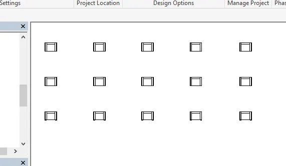
STEP2
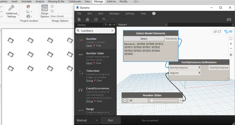
- Go to manage tab->Open Dynamo
- On dynamo page->open node "Select model elements" to select the elements from the revit file
- Open "Number slider" node->maximum value of 360 and steps 10
- To rotate "Familyinstance.setrotation" to perform the rotation task
- project select model elements into family instance and Slider to degree
- Now click on select ->Select family from the revit i.e. the sofa array
- Click on run to rotate the set
4.
AIM:Create a conceptual mass in Revit and develop a parametric column by dividing the surfaces and apply the concepts similar to used in parametric walkway modelling. Use triangular bent or square shaped panels to add finish to the parametric column
PROCEDURE:
- Open revit->Open New family template
- A new tab will open->Conceptual mass folder
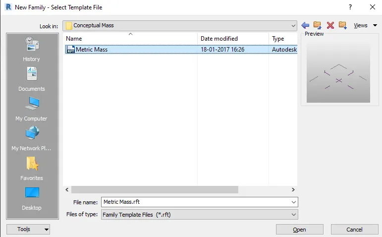
- click Open->Go to elevation view->Create a new level at proper height clearance //In this case is 12'
- Rename the level as "Height of roof"
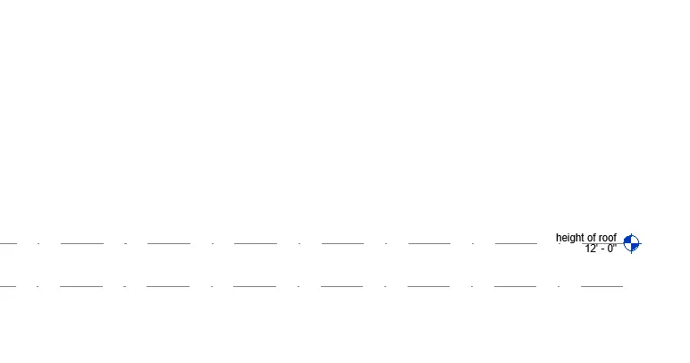
- Go to floor plan ->height of roof
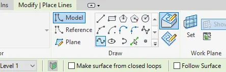
- Create tab->Model lines->Spline curve //Create a curves as you desire
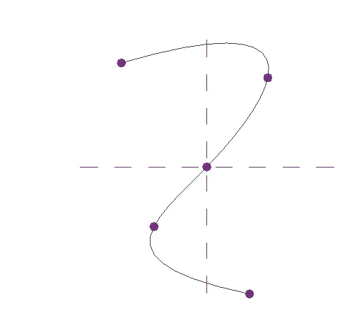
- Now go to 3D view->Set workplane->click on the pointers to set the plane
- go to Circumscribed polygon->go to the plane and draw with sides length similar to height of levels //i.e. sides =12'
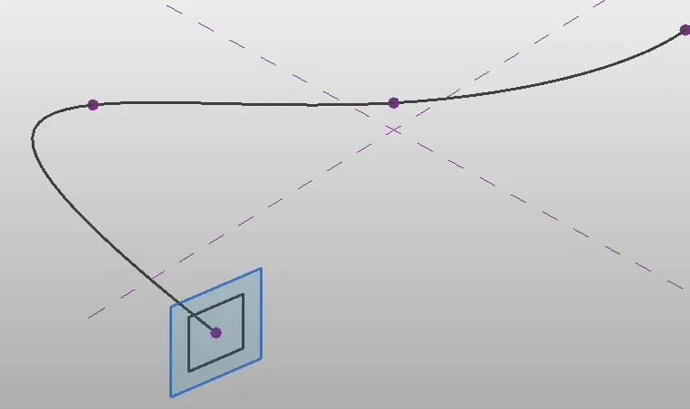
- Do this to each pointers
- Now select the path and The rectangular figure->click on create form
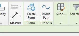
- The form will be created //keep the rectangular base horizontal to the level
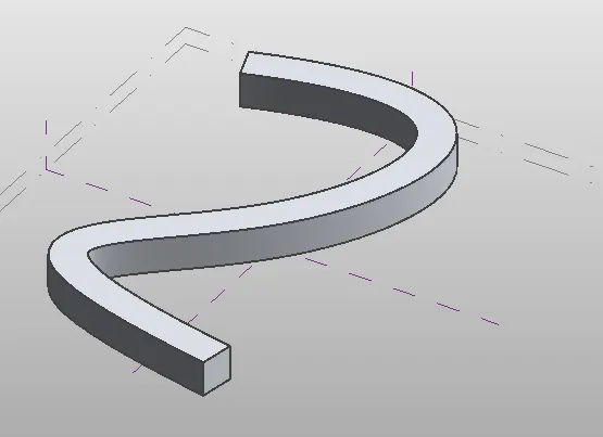
- Now select the object->Filter ,only select the form->OK
- click on Divide surface->from properties panel select the "Triangle bent"
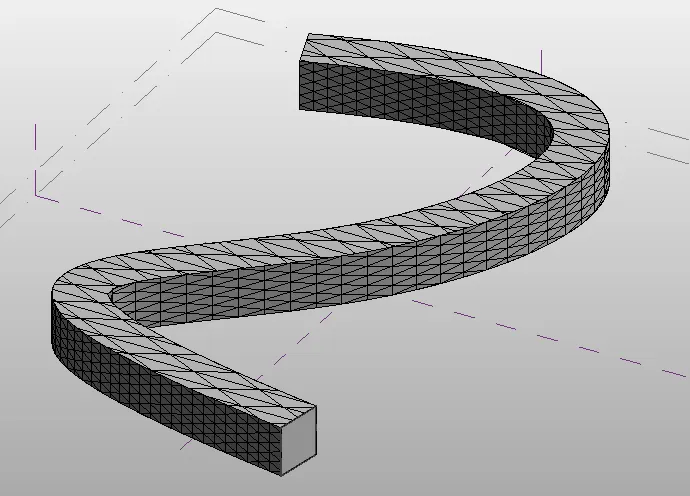
- //Adjust bent surface by changing U-grid and V-grid number
- save the file.
- Go to new->family ->Curtain panel pattern based
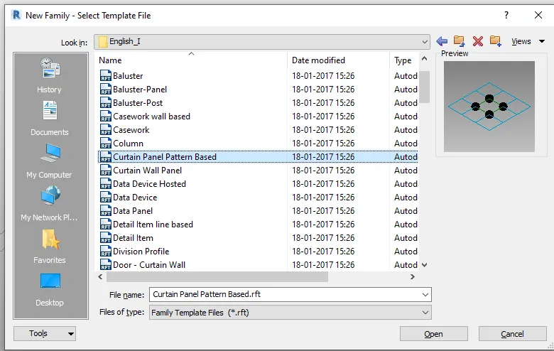
- Open the template->select the base grid->Go to properties panel and change to triangle bent
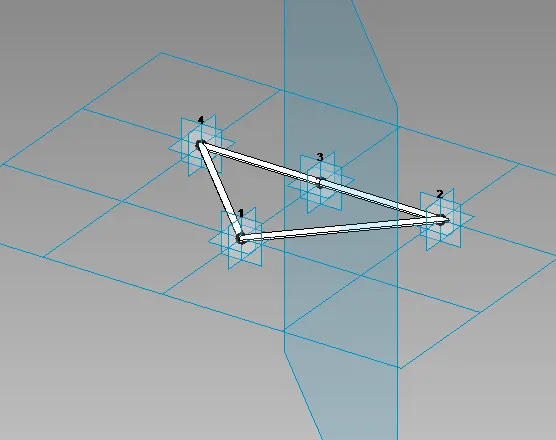
- A new triangle pattern will be shown->From the above tab select refernce point
- Selct the pointAnd select the midpoint of the line of the pattern
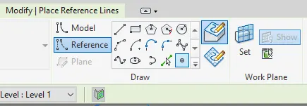
- Now set the plane at that midpoint->Go to draw ->select circle
- Draw the circle on that plane in the midpoint of 3"-10" as per choice
- Now select the line and the circle ->Create form
- Go to the above tab->Load into project
- //You'll be brought back to the project model page
- Select any one side of the divided surface you created //To avoid overloading of software,prefer to do it one by one face
- Go to properties panel->Change the selection from triangle bent to Triangle bent Family1 //it can be family1/Family2 etc.
- DO to for all the sides of spline you want
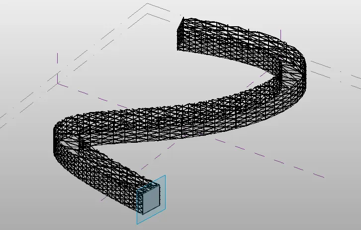
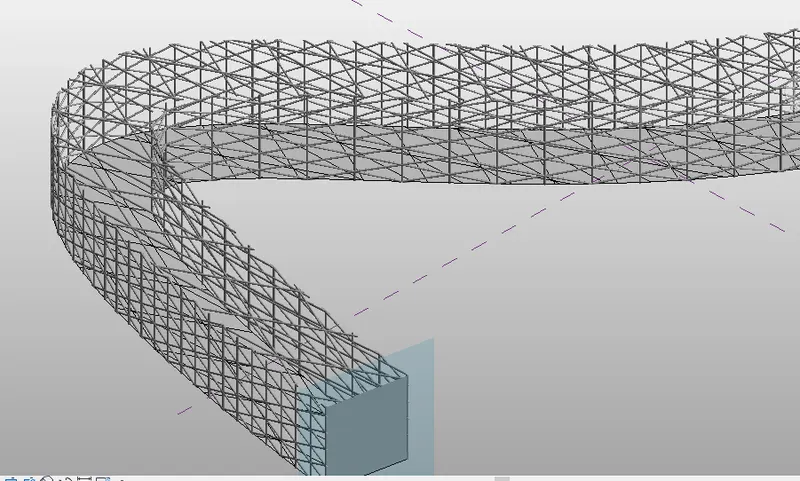
RESULT:
5.
AIM: Use Dynamo to work on developing a Parametric Stadium. List your parameters and use the visual programming approach to complete the modelling, You can use the concepts discussed in parametric high rise tower in class for reference.
PROCEDURE:
- Open revit->Architecture template
- Manage tab->Dynamo
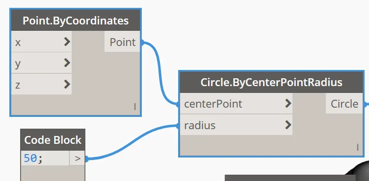
- Open node "Code block","Point.Bycordinates" and "circle.bycenterpointradius"
- Enter code block value 50 for radius //Put base circle value according to your design
- Project the point cordinates into cordinates and codeblock into radius
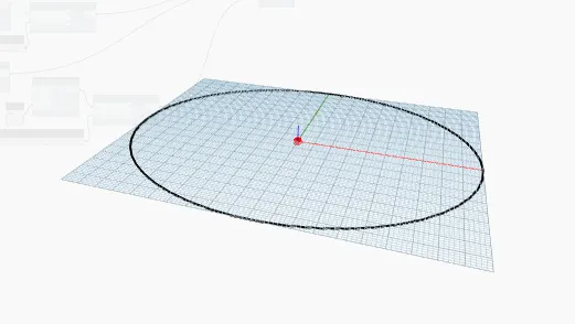
- Run the command,the result given below
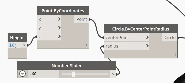
- Copy the nodes and paste it->number slider Steps of 10
- Insert a codeblock->rename it as Height ,input value of 10
- Project the height into Z axis->Now project the cordinates into centerpoitn and slider into radius
- COpy the nodes and paste->Just increase the height with the steps of 10
- Increse the number slider with increment of 50
- //do if for 3-4 times with changing the height and radius values
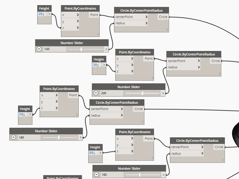
- The result of the above nodes are
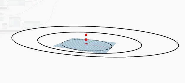
- //Repeat the above steps with changing height and values
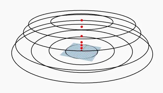
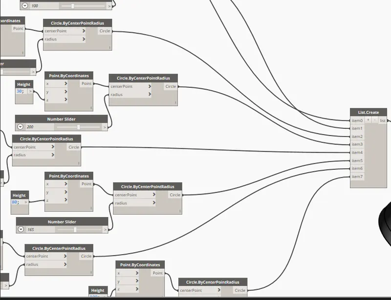
- Now insert a node of "list.create"->create number of items according to the number of radius you have //To take the list of radius
- Project circle nodes into the items
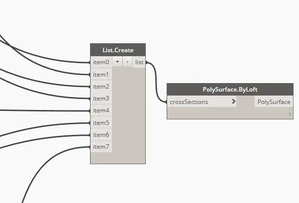
- insert a node of "Polysurface.byloft"->project the list into crossSections of Polysurface //To create a surface
- Run the node
RESULT:
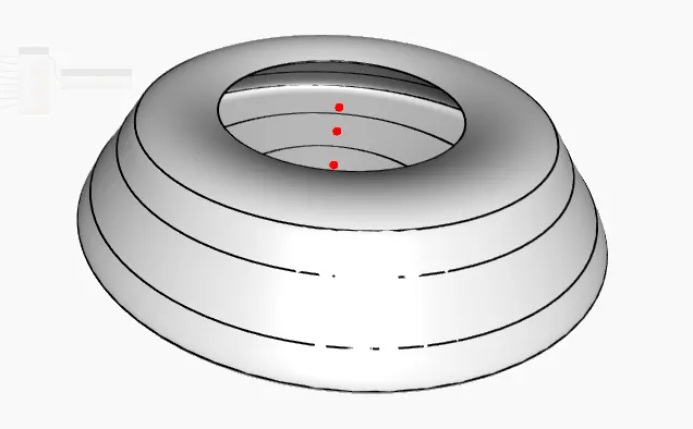
Display in revit 3D