3D Creation of Celing, Roof, Architectural plan, Structural plan, Sectional view, Elevation view and Camera specific view for a house plan using REVIT
1.
AIM:Based on the project saved from Week 3, proceed from the First Floor Level. Model a Ceiling from the architecture tab above the walls at the first-floor level
PROCEDURE:
STEP1
- Open revit
- Open week 3 challenge plan
- Go to Project browser
- ceiling ->Level1
STEP2
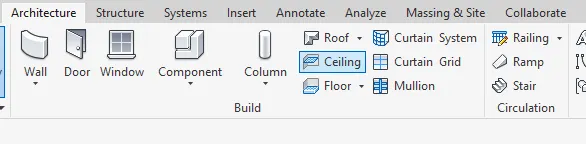
- Go to architecture tab
- Go to Build panel->Click on Ceiling
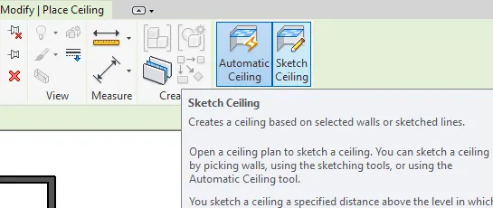
- Go to modify panel-->Sketch ceiling
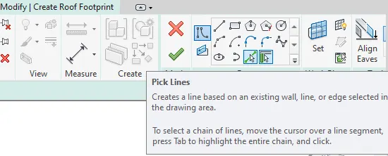
- Select "pick lines" on the modify tab //To select the lines
- Select the lines of the walls ->CLick OK
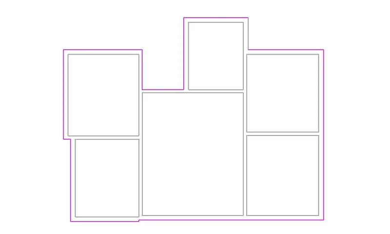
- Click on the Green Tick on the modify to finish //A ceiling will be created
- From the properties panel adjust "Height Offset" //To set the height of ceiling from the ground floor surface
- The ceiling will be created at the required height.
RESULT: Ceilings are given on the height of 9' from the top surface of the ground
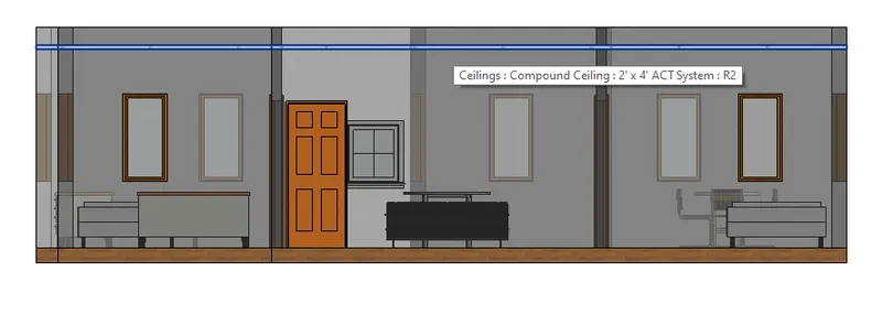 //The blue heighlight is the ceiling at 9' height
2.
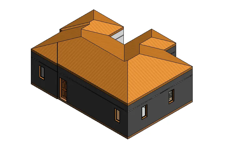
AIM:Model a roof above the ceiling by selecting the footprints of the ceiling. Using the adjustment toolbars appearing on-screen adjust the roof slope to 10 degrees
PROCEDURE:
STEP1
- Open th previous file
- CLick on architecture tab
- Go to "roof" in build panel

- On Modify panel->Pick Lines
STEP2
- Select the exterior lines of the celilings->Click on Tick mark //In case of intersection error,trim the lines
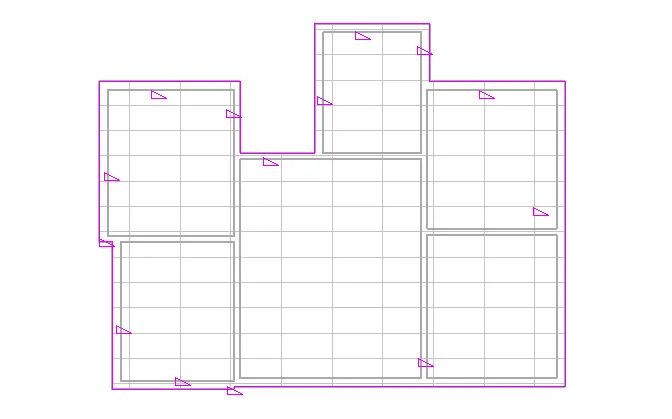
- Now the slope will be added to the roof
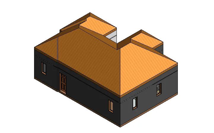
STEP3
- To edit slope angle->Properties->Dimensions
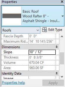
- Slope->enter the value 10 //i.e. 10"/12" in imperial unit
- Click apply->Slope will be modified to 10
RESULT:we added a sloped roof over the ceiling at a particular slope angle
3.
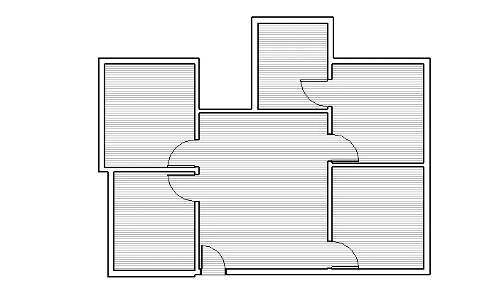
AIM:create plan views for ground floor level and first-floor level including all the walls, floors, and components. Separate them to
architecture and structural plans
PROCEDURE:
- Open Revit
- open week3 file
STEP1
- Go to project browser->floor plan
- select floor 1
STEP2
- Go to view tab
- Select plan views->structrural plan
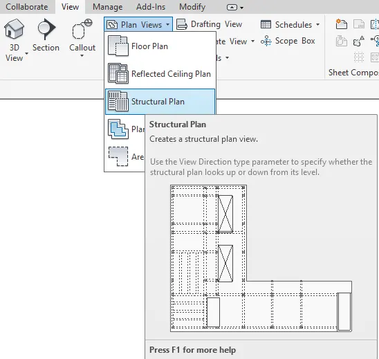
- A new window will open->Click on the level u want structural plan
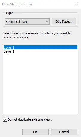
- A structural plan will be made at the project browser.
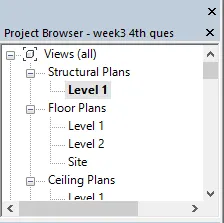
- Right click nd change the name if your want
4.
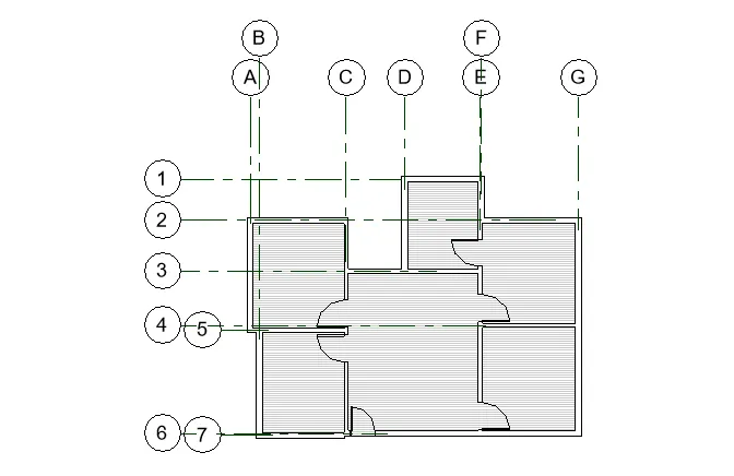
AIM:Using annotate toolbar add dimensions to all the walls and floors with reference to the longitudinal and transverse grids created in the project file
PROCEDURE:
- Open Revit
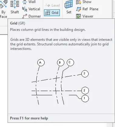
- Go to architecture tab->Under Datum click" Grid"
- Go to project browser->Structural plan
- Select the C/C distance OF walls for grids
5.
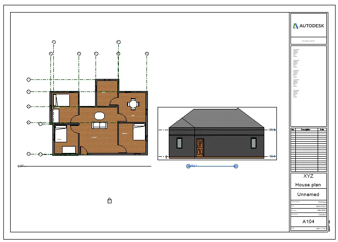
AIM:Create a sheet template from the view tab and adjust the parameters on the sheet to add appropriate views
PROCEDURE:
STEP1
- Go to view tab
- Under sheet composition panel->Sheet
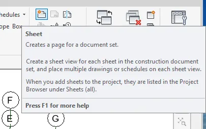
- New window will opne for sheets type
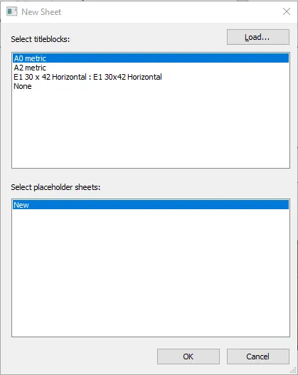
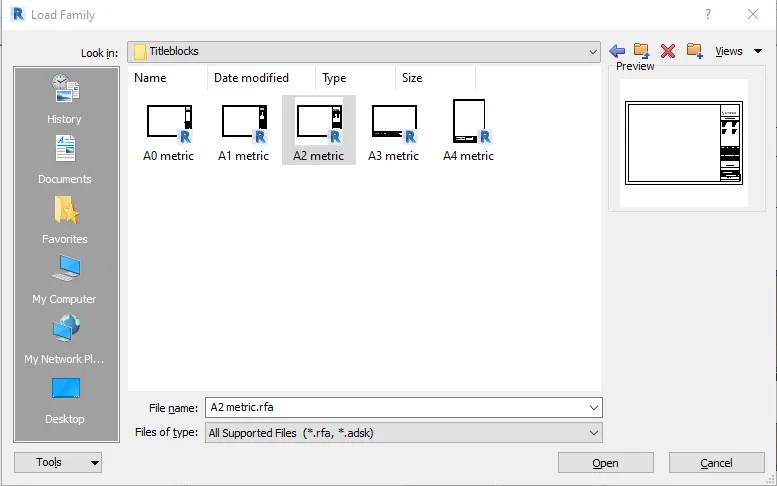
- Choose or load the type pf sheet u want to have //A0 metric sheet is selected
STEP2
- Sheet window will open
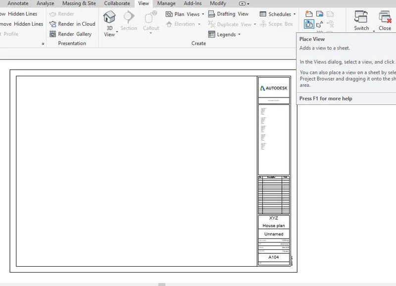
- Under View tab->Sheet composition->Place view
- A tab will open
STEP3
- Choose the plan u want ot enter in sheet //Floor plan->Level1 in this case
- Place it at appropriate place in the sheet
- Adjust the ratio according to the sheet size you selected //From the properties panel
RESULT:
6.
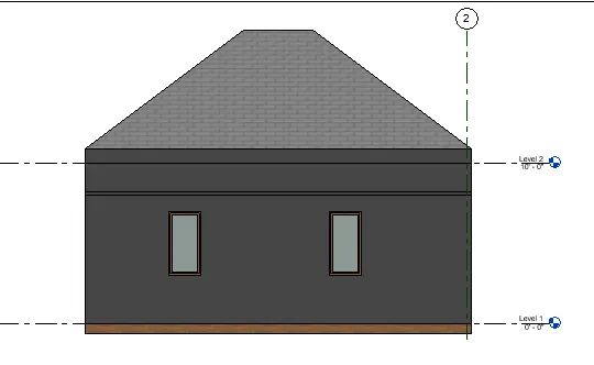
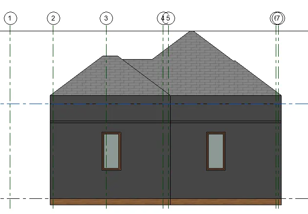
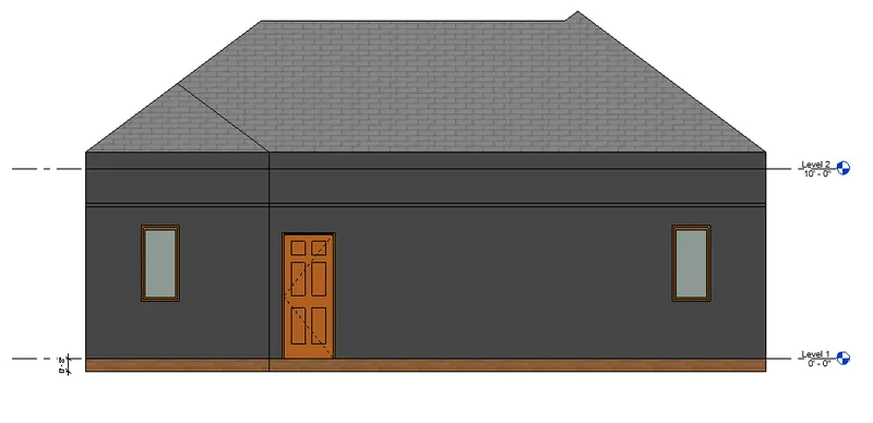
AIM: Using the elevation tab create the elevation views, looking at your building from East, North, South, and West
PROCEDURE:
STEP1
- Open the Floor plan view
- Go to view tab ->Elevation
STEP2
- drag the cursor to the plan and set the elevation side
- To change the elevation view side->Click TAB to change sides
//Do this for all the side of the elevation
- Project browser->Elevation
- Rename the elevation according to their respective sides
RESULT: Click on the elevation side to go to that particular elvation sides from project browser
EAST
WEST
NORTH
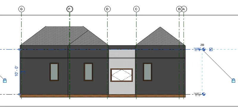
SOUTH
7.
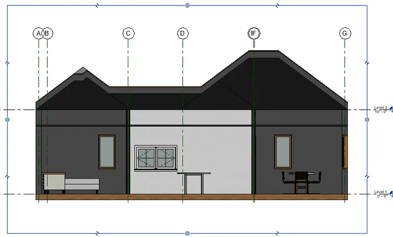
AIM:Produce section cut through each room either cutting across longitudinally or in a transverse direction
PROCEDURE:
STEP1
- Go to project browser ->Open floor plan level1
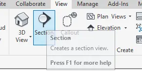
- Go to View Tab->Create->Section
STEP2
- Draw a line running through the plan longitudinally or transverse
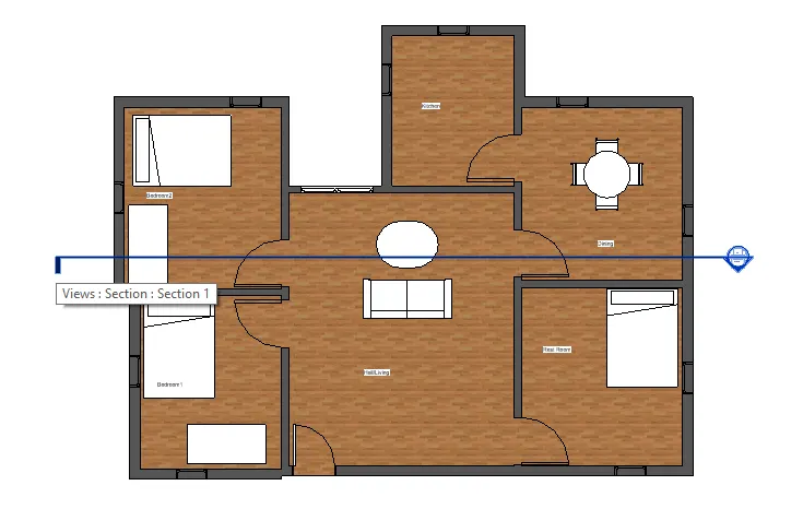
- Go to project browser->Section plan
RESULT:The sectionla view of the plan will be shown
From SOUTH
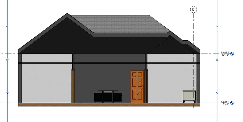
Feom NORTH //Click on Flip ⇅ to change the section sides
8.
AIM: Classify the views, Plan Views, Section Views, and Elevation views to either Design or Documentation category using Properties browser
PROCEDURE:
STEP1
- Open REVIT
- open the last file you saved
STEP1
- Go to view tab->Sheet
- Load->A1 metric sheet //Sheet page will open
- Go to MAnage->Project information //Edit the parameters
STEP1
- Go to View ->Place view
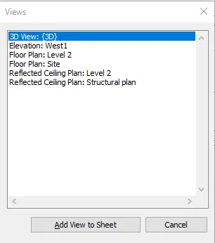
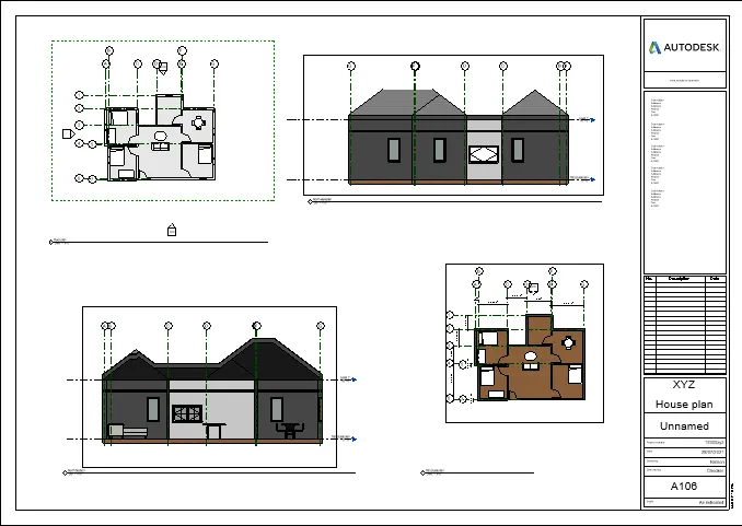
- Select the part u want ot present in the sheet
//Similarly select the plan,section,elevation of the plan to be shown in the sheet
RESULT:
9.
AIM: Using the sheet template produced create multiple sheets as follows
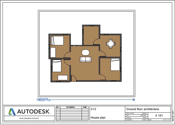
a. A 101- Ground Floor Architecture Plan
b. A 102- First Floor Architecture Plan
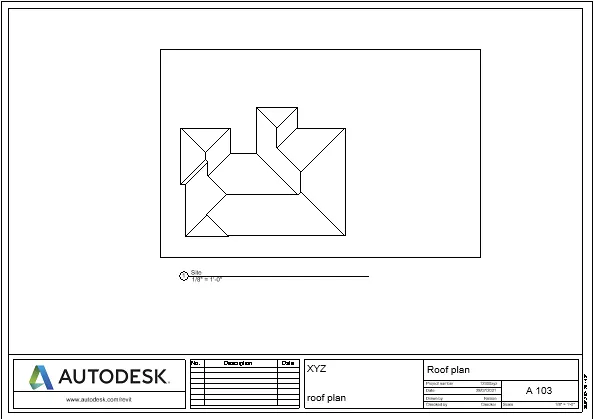
c. A 103- Roof Plan
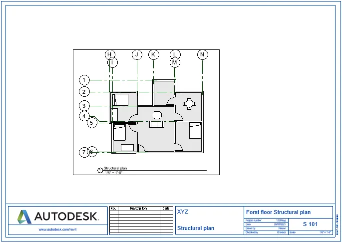
d. S 101- Ground Floor Structural Plan
e. S 102- First Floor Structural Plan
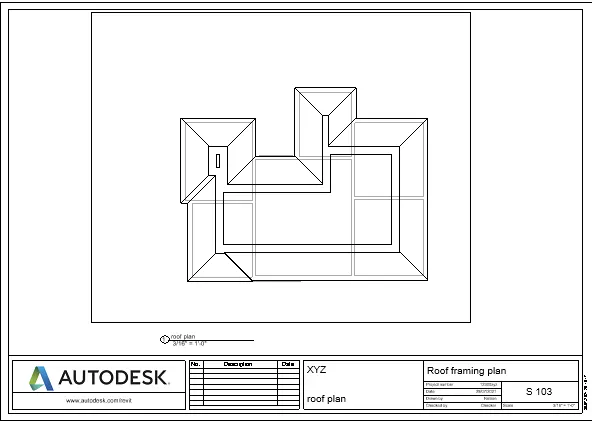
f. S 103- Roof Framing Plan
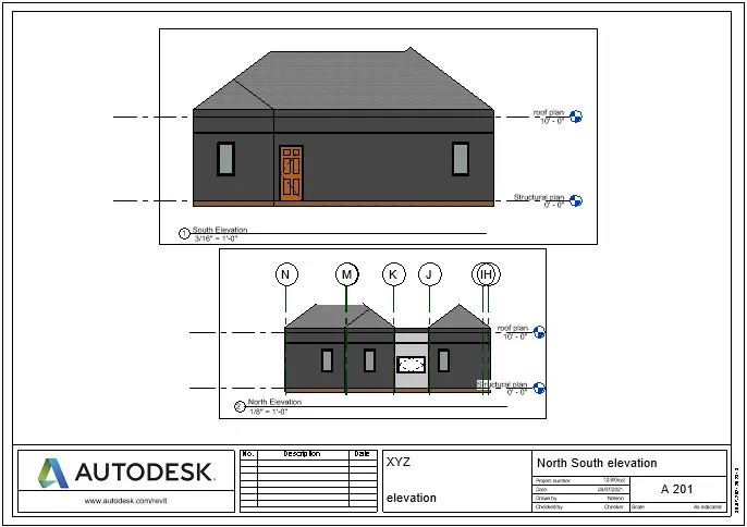
g. A-201- North-South Elevations
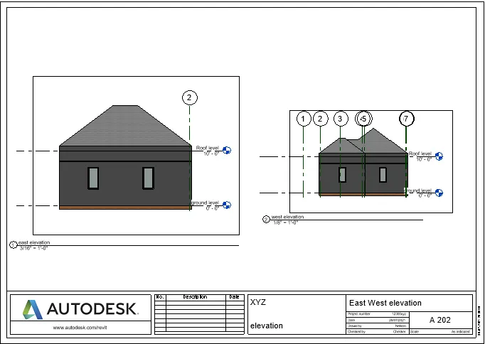
h. A-202- East-West Elevations
PROCEDURE:
STEP1
- Open revit
- Go to the file your saved in previoues part
STEP2
- Go to architecture tab->Sheet
- Select the size of sheet you want //A3 Metric sheet in this case
- Go to Manage tab->Project information
- Edit the details you want in the sheet
STEP3
- Go to View tab->Place View
- Select ground floor plan->Click OK //Floor pplan level1 will be added
- Go to properties->scale(To adjust the scale accordng to the size)
- Can edit the View name for the plan in prooperties
RESULT:
A 101 Groudn floor architectural plan
//A 102 Similarly do it for first floor architecture plan
//Repaeat step2-3 for making new sheet and keeping the plan inside
- Go to place view
- select roof plan->Right click and rename it
- Go to properties to adjust the scaling
A 103 Roof plan
S 101 Ground floor structural plan
S 103- Roof Framing Plan
A-201- North-South Elevations
A-202- East-West Elevations
10.
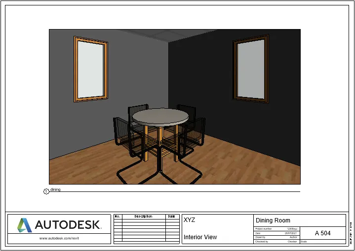
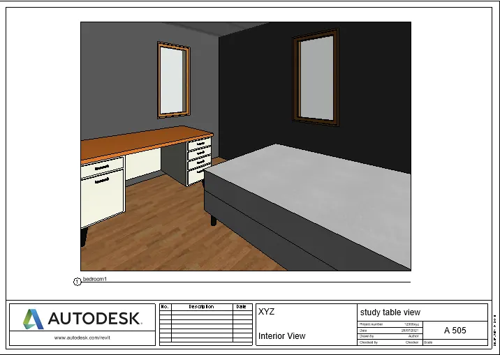
AIM:Create a camera-specific view or a 3D view in each room
PROCEDURE:
STEP1
- Open revit
- Go to project browser->ground floor
- Go to view tab->Under create section->Camera
- Place the camera at suitable place and angle
STEP2
- A new window will open
- adjust the camera view as per the visibility
- Go ti visual style ->Realistic
STEP3
- Go to project browser->Click on the 3D view
- Rename the view as per requirement
STEP4
- Go to view tab->Sheet
- Create the sheet as per your requirement //In this case A3 metric paper
- Go to manage->Project information //Edit the parameters information
- Go to modify panel->place view
- Select the 3d view you want to place on sheet //Adjust the view position in sheet by cursor movement
RESULT:
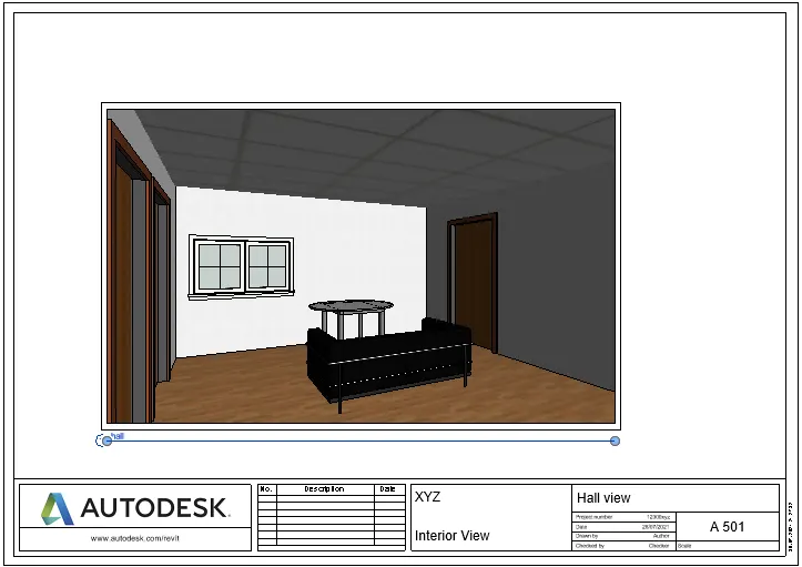
A 501 HALL VIEW
//Repeat the step4 to create the new sheet for different view
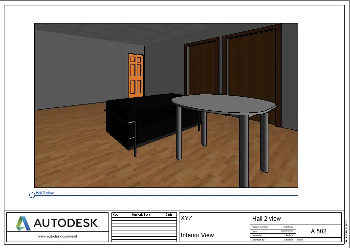
A 502 HALL 2 VIEW
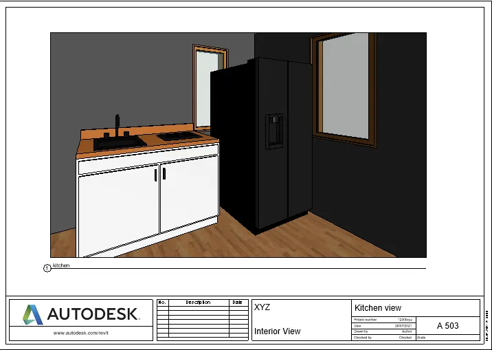
A 503 KITCHEN VIEW
A 504 DINING ROOM
A 505 STUDY TABLE
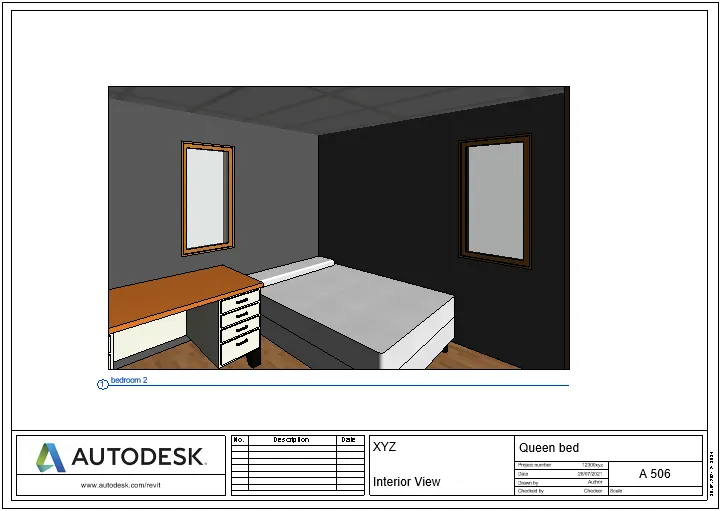
A 506 QUEEN BED