Introduction to REVIT concepts
1.
AIM:To open a new file and save it giving an appropriate name
PROCEDURE:
- Open revit
- open new file
- open the file
- save it with approporiate name
STEP1
- Open REVIT software.
STEP2
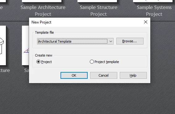
- Under the file menu
- Click "New"
- Select the type of template u want //(Construction/structural/architechtural)
- Click on Project
- CLick on ok
STEP3
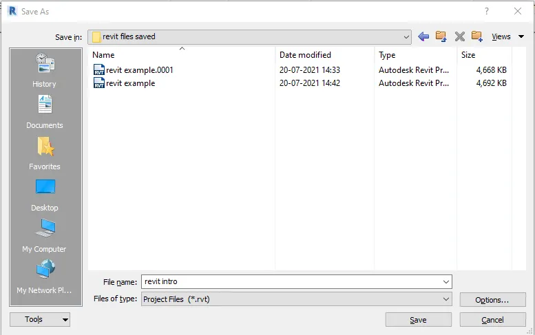
- Click on save option
- Name the new file as "revit intro"(as your choice)
- click ok
RESULT:
2.
AIM:Save the new project file. Close and open using icons from file toolbar
PROCEDURE:
- save the file
- Close revit
- open again
- click on the open icon
- click the file to open
STEP1
- click on save from the previous file "revit intro"
- Close the file
- Click on the "open" file icon
- a new window will open
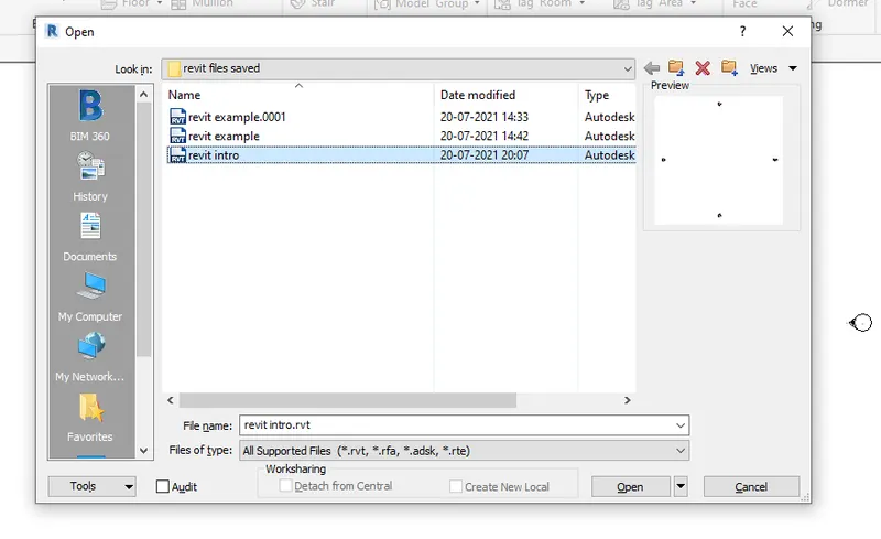
- click on the file u want to open(in this case "revit intro.rvt")
- Click open
3.
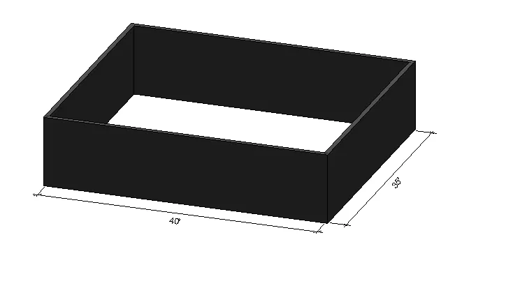
AIM:From the architecture/ structure toolbar familiarize with options to draw a wall. Create a rectangular layout of walls of about 40’-0” X 35’-0”
PROCEDURE:
- open the file
- go to draw panel
- draw the rectangle
STEP1
- Open the file revit intro.rvt
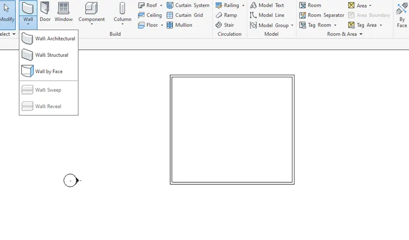
- Click on architecture panel
- select any one wall type (architectural selected) //Architectural,structural,wall by face
//Now a cursor will be shown in the drawing space
- draw a horizontal line of 40' //Starting from the top left corner
- pull the cursor down and draw a line of 35'
- go 40' towards left (in horizontal direction)
- connect the ends of the walls //it'll join the walls
RESULT:
4.
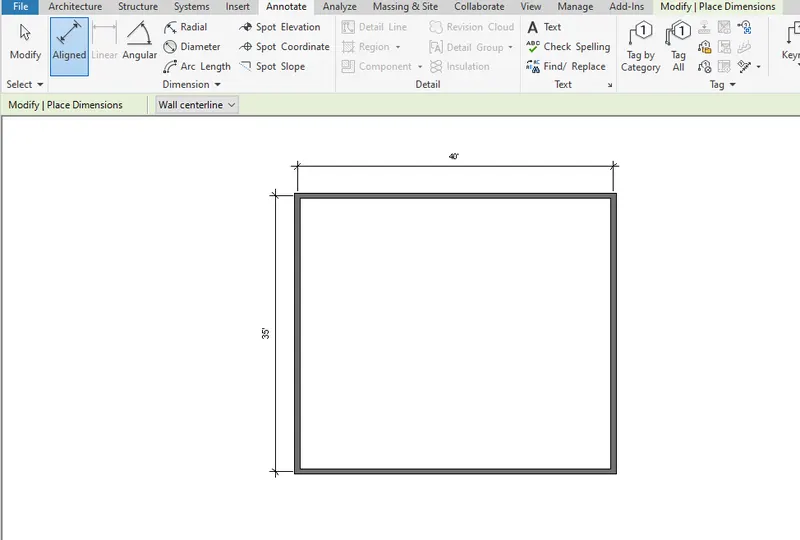
AIM:From the Annotate toolbar use the aligned option to add dimensions to the layout
PROCUDERE:
- go to annotate bar
- select the aligned dimension
STEP1
- Go to annotate bar
- select the aligned dimesion
STEP2
- select the endpoint of horizontal direction wall //Shows 40' length
- click "shift" to change the direction of the dimension to take //Switch between horizontal and vertical direction
- Click on vertical direction wall from one end to another end
RESULT:
5.
AIM: Use the project browser to switch to different wall types
PROCEDURE:
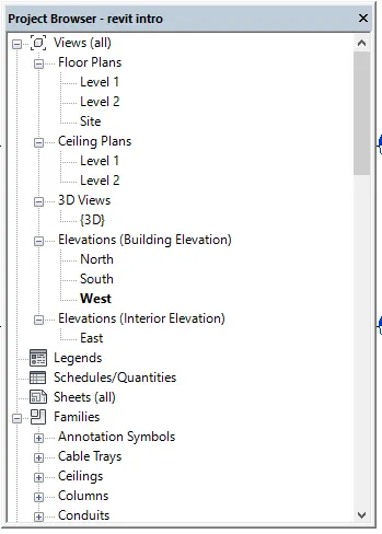
- open project browser
- go to families title
- search for walls title
STEP1
- open th project browser panel
STEP2
- Go to families title
- Expand the title
STEP3
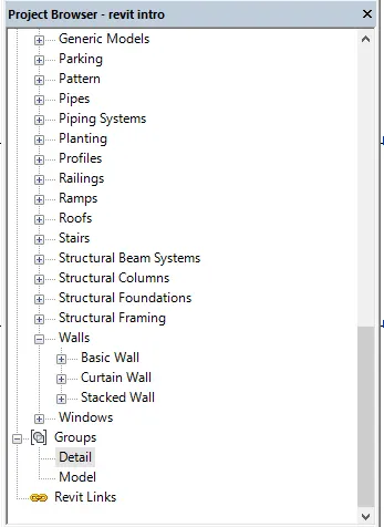
- go down to the walls title
- expand the wall title
- subtitle will be 1.basic 2.curtain 3. stacked walls
- Choose the one u like to use
6.
AIM: Create a 3D view from the view toolbar and save the view with the appropriate name
PROCEDURE:
- view bar
- 3d view toolbar
- Properties
STEP1
- Go to the view bar
- click on the 3DVIEW //To go to 3D view of the drawing
- Now the 3D view will be shown
STEP2
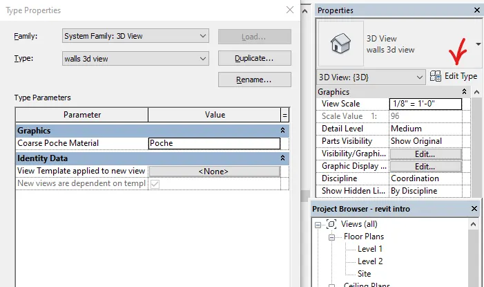
- Go to the properties panel //Properties panel at the right side of window
- Click on "Edit Type"
- A new panel window will open
- Go to "rename" and change the name to "walls 3d view" //To input the new name
RESULT:
7.
AIM: Navigate through the 3D model using the view cube. Orbit/pan through the model layout created
PROCEDURE:
- Use theview cube
- Use the navigation tool to navigate
STEP1
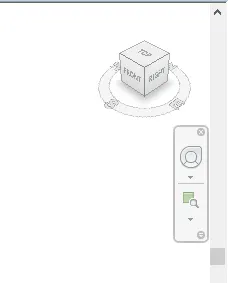
- Click on the View cube on the top right corner.
STEP2
- Left click on view cube
- move the cursor around in the different direction to move the obect in orbit
STEP3
- Click on navigation panel
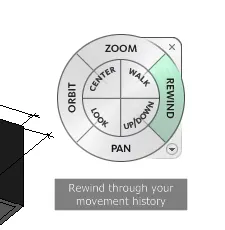
- A panel will open as shown above
STEP4
To Pan
- Click on pan
- left click and move the cursor around to pan the object on window //to pan the object
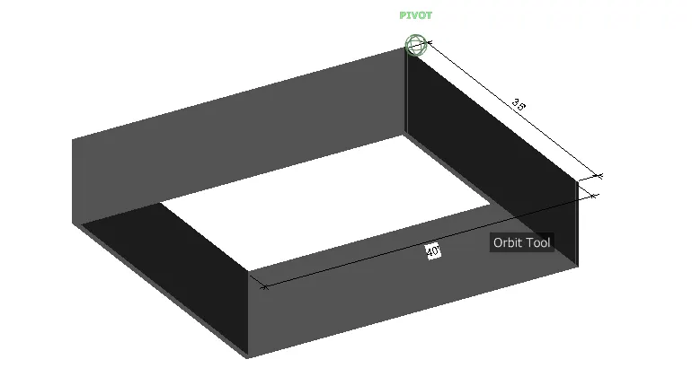
To Orbit
- CLick on the orbit
- move the cursor in circlular or any direction to change the orbit
8.
AIM: Use the visibility settings option below to switch model to shaded, realistic, hidden lines options
PROCEDURE:
- Go to Visual style
- select different modes
STEP1
- Go to Visual style located at the down left bar //In shape of 3D rectangle
- Click on the icon
STEP2
- Different visual style wil be shown
- a.Wireframe
- b.shaded
- c.hidden
- d.realistic
- e.consistent colors
- Ray trace
STEP3
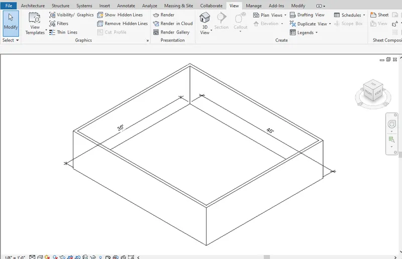
- Go to Hidden
- It hides the lines which are behind an object or walls
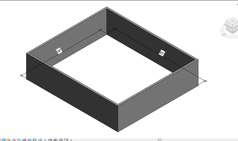
- Go to Shaded
- It shows the shaded view of the object
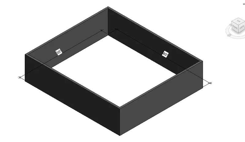
- go to realistic
- it show the realistic view of the object
9.
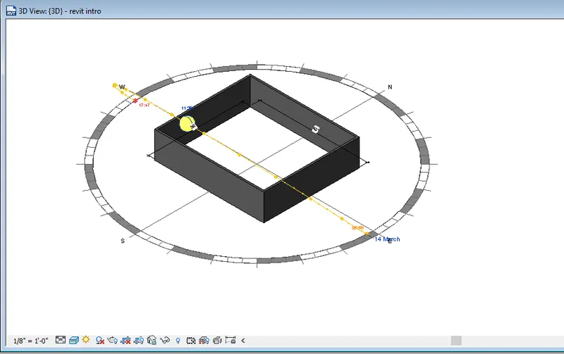
AIM:Turn the sun path on and off to view shadings in the layout created
PROCEDURE:
- Go to sun path icon
- turn on the sun path
STEP1
- Go to bottom left corner
- Click on "Sun icon" i.e. the sun path icon
- click "Sun path on" //To turn on sun path
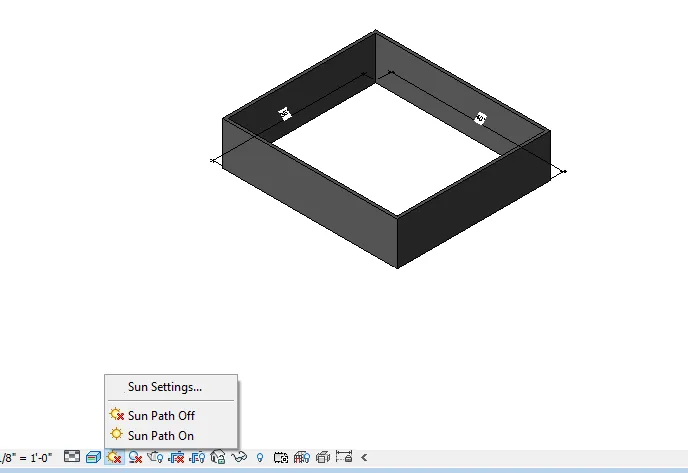
- Sun and the direction will be shown //Adjust the path of the sun according to the requirement
RESULT:
10.
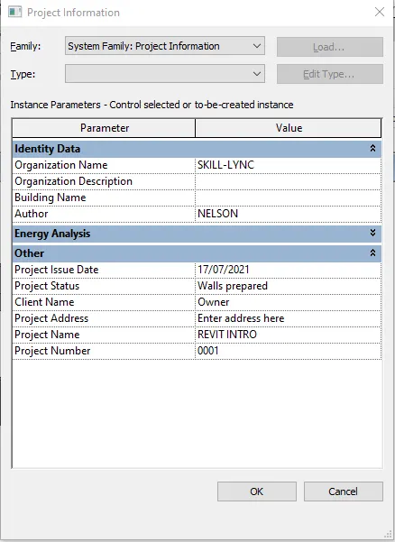
AIM:Use the Manage toolbar to enter project settings, project name, and project issue date (choose according to your convenience).
PROCEDURE:
- Go tot manage toolbar
- Project information
- edit
STEP1
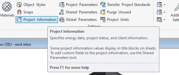
- Go to the manage toolbar
- Click on "project information"
STEP2
- A new window will open
- Type the info as convinient
RESULT:
11.
AIM: What is the Analyze toolbar used in Revit? How it is beneficial for design and modeling
ANS.
- Analyse toolbar helps you to perform analysis on our structural building.
- The boundary conditions enable you to define point line and area boundary conditions in an analytical model.
- It also helps in applying structural loads to your analytical model to assess possible deformations and stress in your design.
- You can apply point, line, and area loads to your analytical model.
- It also helps in applying different load combinations t the structure.
- it helps in adjusting setting for automatic checking analytical/physicalmodel consistency,tolerances and analytical physical model consistency checking.
- Apply structural loads to your analytical model to assess possible deformations and stress in your design.You can apply point, line, and area loads to your analytical model.
12.
AIM: What are the links that Revit supports to be linked to the model?
ANS: There are many links provided by revit ,This is provided to work on other files and edit/modify it in the revist software.
Some of the links provided by the revit are:
Go to the INSERT toolbar Now there will be shown the links as
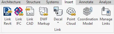
- Link REVIT: It helps to link one revit file into another current files .It helps in combiling the different disciplines of the files
- Link IFC :IFC files are building information modeling files used to take the information for developing designs in revit
- Link CAD: It helps in importing the 2D cad files into the revit ot draw 3d models out of it.
13.
AIM: Why do you need the Collaborate tab in Revit? How it supports modeling and its efficiency
ANSWER
- You can link multiple Revit models together, allowing team members to work in context.
- Through worksharing, users on the same local area network (LAN) can work together in the same Revit model.
- When collaboration needs to occur among users who are not in the same geographic location, use Revit Server or Revit Cloud Worksharing.
a.Revit Server connects offices who share a network but are not in the same geographic location.
b.Revit Cloud Worksharing is a cloud-based service that allows any Revit users inside or outside a network to collaborate on a Revit model.