Creating Architectural and Structural model with 3D rendering using REVIT
1.
AIM:Select the type of structure you want to build from one of the three below:
a. Multi-Unit Residential Apartment
b. Office Buildings
c. School
ANSWER: The type of structure i want to select is Multi Unit Residential Buildings
2.
AIM:Assume reasonable assumptions for geographic and location details for your project modeling. Based on assumptions and type of structure selected identify the modeling requirements from NBC
ANSWER: My assumed location is Kirandul PIN:494556
The road width is 20ft accoridng to which my maximum byilidng height is under 35ft.
3.
AIM:Using the structural model, include the following components based on the type of structure selected
a. Foundation – Isolated / Wall/Matt Foundation
b. Columns
c. Beams Connected to Columns
d. Roof Framing/ Truss
e. Floor / Decks
f. Floor Openings for Elevators and Stairs
PROCEDURE:
- Open Revit->structural template
- Structural panel->Datum->Grids //make the grids for the following plan
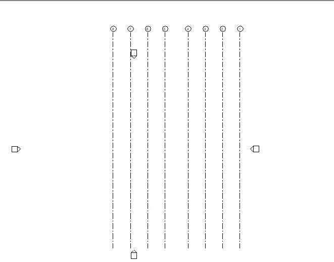 //Similarly make the horizontal grids
- Go to elevation from project browser->Elevation
- structure panel->Datum->Levels //Create levels accordingly
a. Foundation – Isolated / Wall/Matt Foundation
- Go to structural panel->Isolated footing->On modify(Select grids) //Select the vertical an horizontal grids to put footing
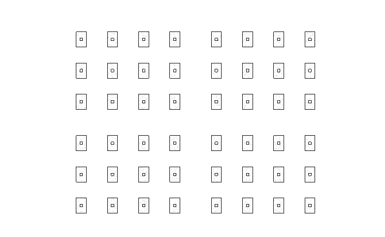
b. Columns
- Go to structural tab->Column->Select the size from project browser->Select 'On grids' //The column will be applied to that floor
- Select all the object->Filter only Columns->Copy ->Aligned to selected objects //To copy to all floor
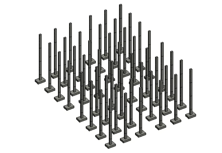
c. Beams Connected to Columns
- Go to structural tab->Beam->Select the size of beam from project browser->Select 'Line" on modify panel //The column will be applied to that floor
- Select all the object->Filter only beam->Copy ->Aligned to selected objects //To copy to all floor
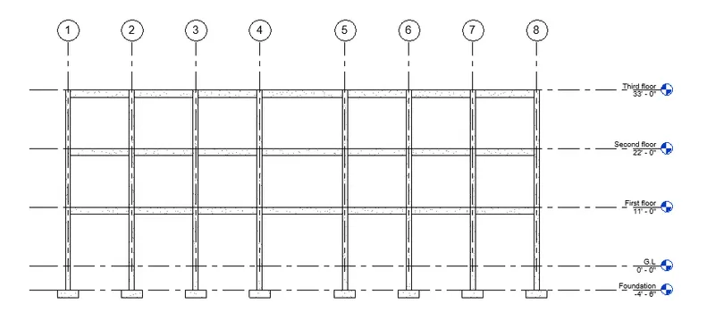
d. Floor / Decks
- Select floor on the structural panel->Select "Line" on modify tab //Draw line on where you want the floor area
- Select all the object->Filter Only floor->Copy ->Aligned to selected objects //To copy to all levels
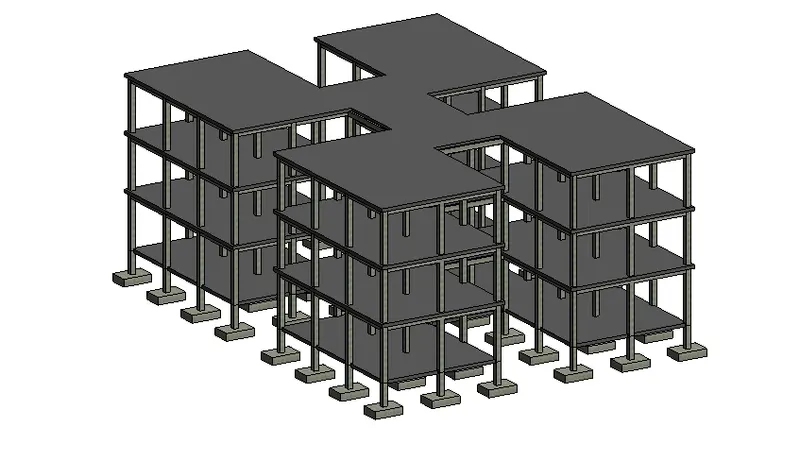
4.
AIM:Using the architectural model, include the following components based on the type of structure selected
a. Wall Layout with appropriate material and finishing b. Exterior façade with fancy finish
c. Interior partition walls to size rooms
d. Components to add details to a room ( Desk, Chair, Lighting, Plumbing fixtures)
e. Add components such as stairs Elevators
f. Have at-least one side of the building with curtain walls and glass panels
g. Include interior and exterior lighting fixtures
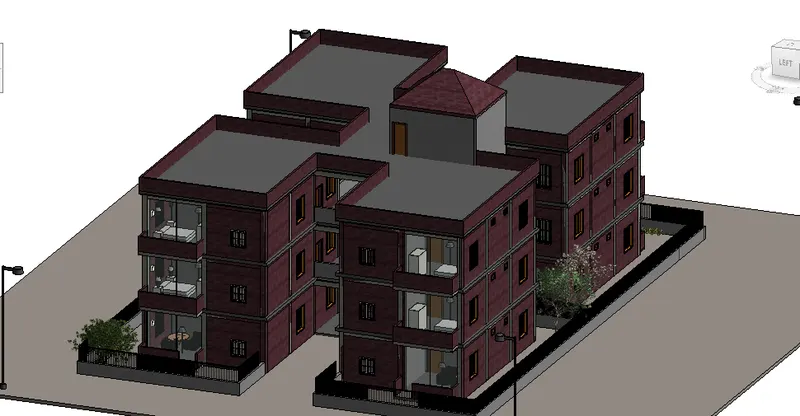
h. Place proper topographic components from outside ( Trees, Parking, Plants) to add details to the model
PROCUDURE:
- Save the Structural file you made above as central file->Synchronize the file with the central
- Open new file->architectural template
- Link the above file in the architectural file
Wall Layout
- Go to archittectural tab->Walls->Modify "Line" //Select the lines where u want the walls
- Go to properties panel to change the wall type
- Select the 6" wall for the partition walls
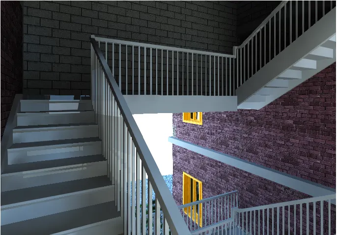
- Go to sArchitecture panel->Stairs ->Select the run to add stairs
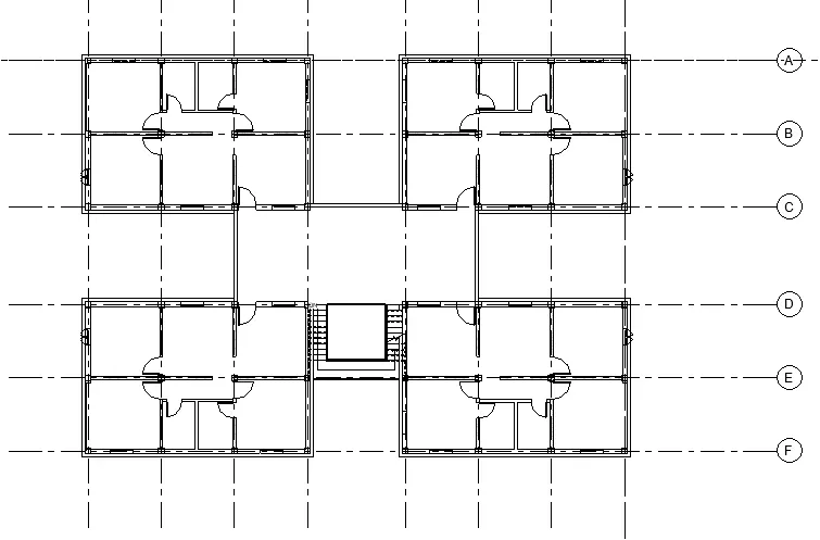
Interior Components details of room
- Go to project browser->Families //Select,table,chairs,sofa according to the appropriate design
- To load Families->Insert->Load family->Go to particular folder you want the elements of
- Drag the element in the plan
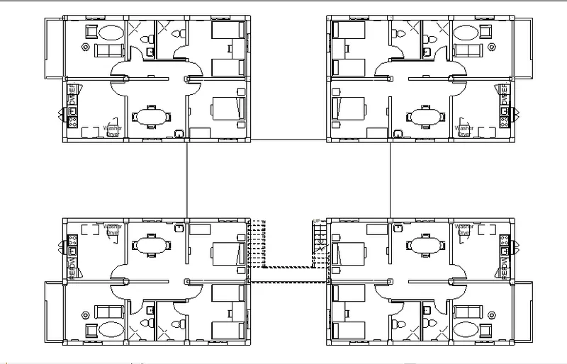
Stairs:
Toppgraphy Components
5.
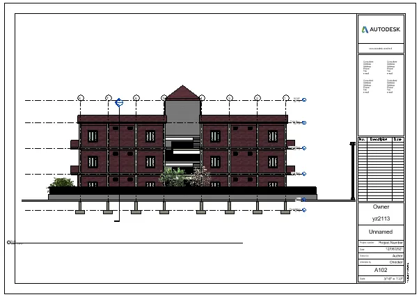
AIM: Provide a set of drawings in an architectural and structural model to list the following details with categories and appropriate sheet templates included
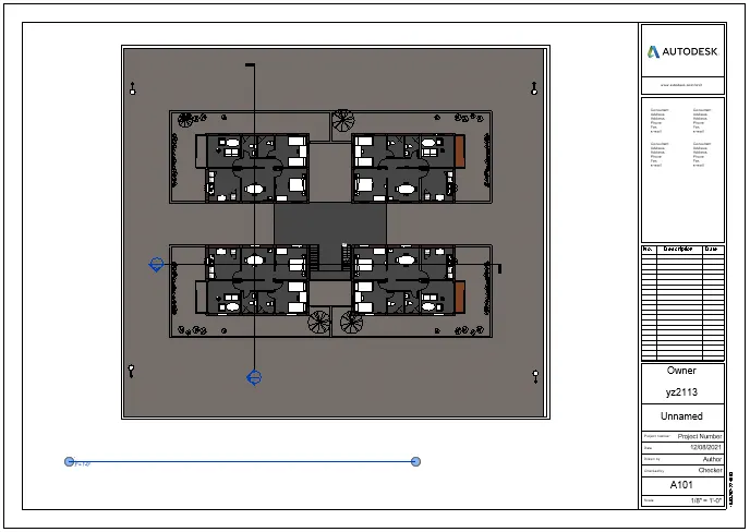
a. Floor Plans with Annotations
b. Elevations
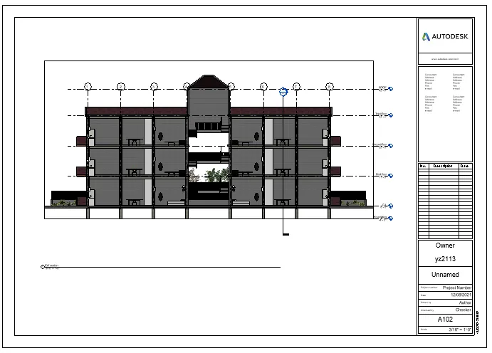
c. Sections
PROCUDURE:
- Go to view tab
- Sheets
- click on appropriate sheets
- add the sheet
- Go to place view->Select the view you want to save
- Go to properties panel to adjust the scaling of the drawing in the sheet
Ground floor plan
East elevation
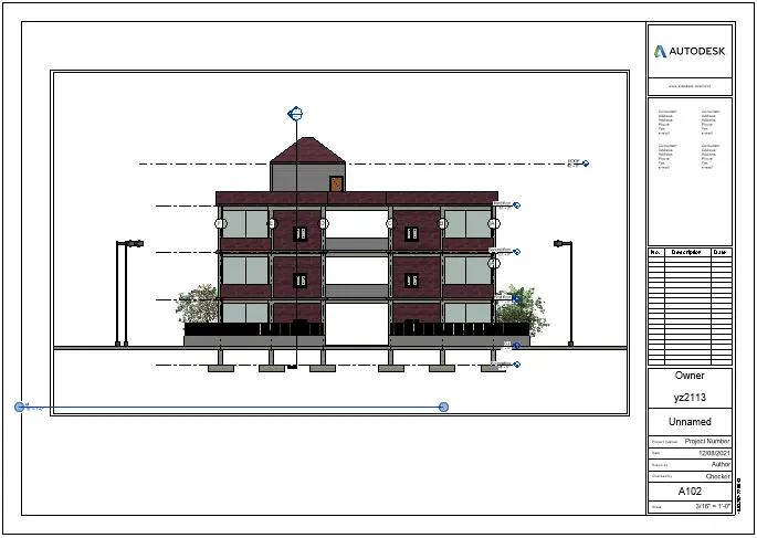
South Elevation
Section View
6.
AIM: Using the Rendering settings, Render images of the 3D model produced and include the rendered images to the drawing sheets
a. Rendering from interior rooms
b. Rendering from out showing topographic features
c. Rendering through structural framing
PROCUDURE:
- Go to view panel->Camera ->set the camera at a point u want perspective of
- Seth the camera angle
- A view page will open
- Go to view tab->Render
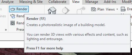
- Selected region->Mark the region you want to render-> Click on "Render"
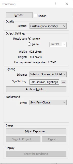
- Adjust the exposure to reduce or increse the light effects
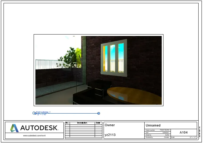
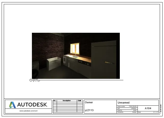
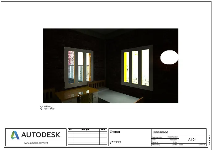
a. Rendering from interior rooms
Living room
Kitchen
Bed room
b. Rendering from out showing topographic features
Builidng View

c. Rendering through structural framing
Structural frame rendering
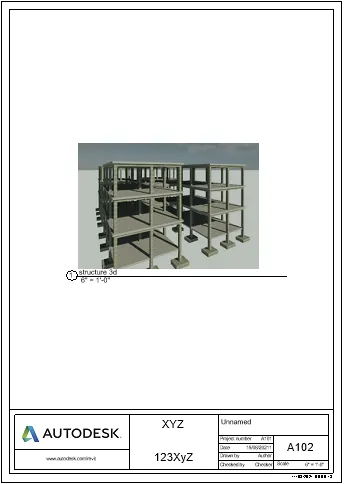
7.
AIM: Print the set of drawing sheets created and submit the drawings from the architecture and structure model
PROCUDURE:
- Open revit file
- Go to file tab->Print
- A new page will open->Select view sheet //To select the sheet you want to print
- Click on print
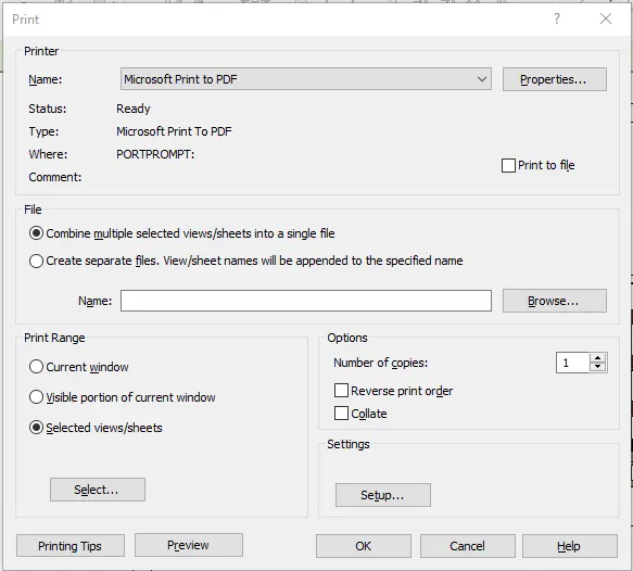
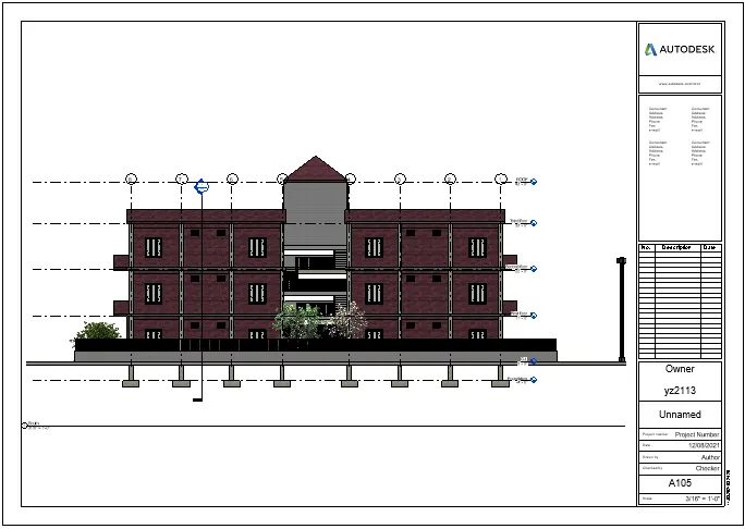
- I've selected the south elevation of the model
RESULT: