Creating 3D Isometric view of various structural elements in AutoCAD
1.
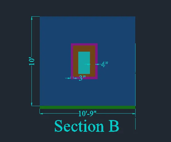
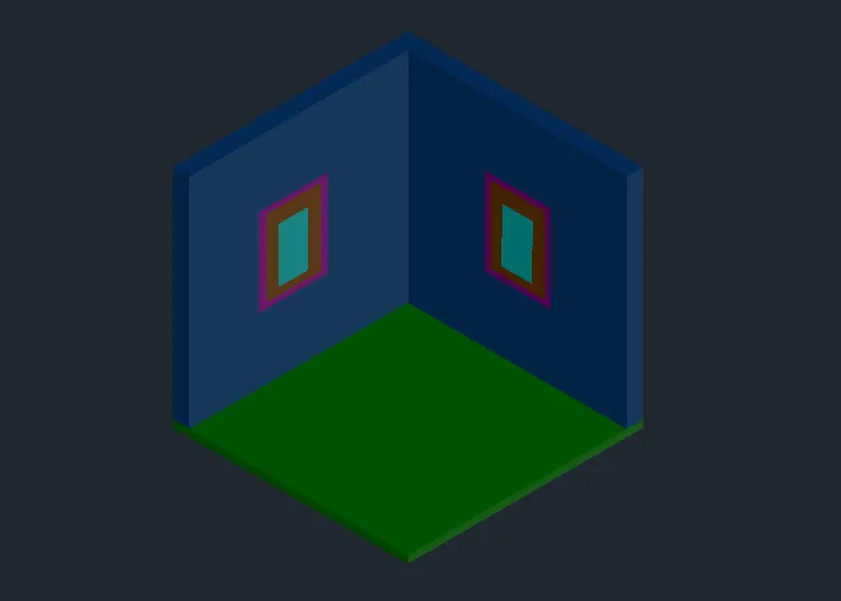
AIM:Create a 3D Isometric View of the building with plan and elevation given.
PROCEDURE:
- To create the plan
- To To joing the line
- amke it region
- Extrude,Polysolid
- Subtract
- Press/Pull
STEP1
- Go to 3d modelling
- Go to Isometric view
STEP2
Command:BOX
- Create a box of size 10'9"x10'9",Click enter //For the base
- Enter the height of base as 4"
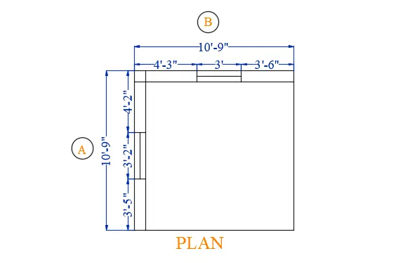
Command:POLYSOLID
- ENter the width =9"
- Enter height as 10' from the top of the base //For height of walls
- Justify As LEFT
- Create the wall arounf the edges of the base
STEP3
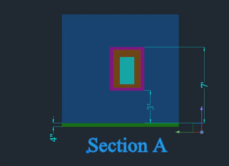
Command:RECTANGLE //FOR MAKING WINDOW
- Create a rectngle of 3'x4' //For the size od window
Command:OFFSET
- TAke an offset of 3" inside //For the window panel
- Take anther offset of 4" inside //For width of panel
STEP4
Command:TRIM
- TRIM the extra line from the window
Command:PRESS/PULL
- Select the window glass region and give height of 7" //In Z AXIS
- Select the window panel region and give height of 8"
- Select the region between for the window and height of 9" //For the outer border
Command:COPY
- Copy the window design and paste it in the wall at height of 3' //3' from the base and lateral dimesions
- //Copy it on the other side walls according to the later distance provided
STEP5
Command:SUBTRACT
- Select the main object //From which u want to subtract
- Select the object which u want to subtract
Command:COPY
- Now copy the window object in the subtracted place on the walls.
Command:BOX
- From the top of the walls take 10'9x10'9 base //From the point of intersection walls
- Give a height of 5"
STEP6
Command:LAYER
- Create layers of name walls,base,windows ,dimensions //To give different colour and properties
- Select the particular object and assign the layer to it
Command:DIMLINEAR
- Select the two point where u want to show the distance
- Select the dimension and assign the layer to it
RESULT:/
2.
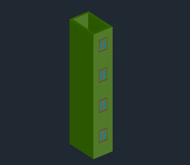
AIM:Create the 3D View of the Building Façade as given in the plan and elevation. Also, see the detail of the window.
PROCEDURE:
- To create the plan
- To joing the line
- make it region
- Extrude,Polysolid
- Subtract
- Press/Pull
STEP1
- Go to top view
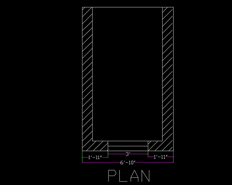
Command:RECTANGLE
- Create a rectangle of 6'10"x10'9" //For the plan
Command:OFFSET
- slect the rectangle and take offset of 9"inside //To show the thickkness of wall
- From the exteriox edge take offset of 1'11" from both the sides //For the width of window
- Take offset of 4.5" of horizontal wall //for the winodw partion
STEP2
Command:TRIM
- TRIM the extra lines of the drawing //The edges lines of walls etc.
Command:LAYER
- Create layers of name dimensions,walls .windows,panels etc
- provide different colours to them //It ease in distinguishing the object
STEP3
Command:DIMLINEAR
- Select the point in between the lines to show the length. //Dimension on the plan
STEP4
Command:POLYSOLID
Swith to ISOMETRIC view
- Give width of 9"
- Give height of 40'10" //For total all floor
- Justify right //To start from the left sid eof the building
- Draw the polysolide above the plan made earlier
STEP5
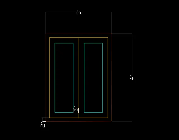
Command:RECTANGLE //FOR MAKING WINDOW
- Create a rectngle of 3'x4' //For the size od window
Command:OFFSET
- TAke an offset of 2" inside //For the window panel
- Take anther offset of 3" inside //For width of panel
Command:LINE
- Draw a line form the center of the window for window panels
Command:OFFSET
- Take offset of 3" on both the sides of the line
Command:TRIM
- TRIM the extra line from the window
STEP6
Command:PRESS/PULL
- Select the window glass region and give height of 7" //In Z AXIS
- Select the window panel region and give height of 8"
- Select the region between for the window and height of 9" //For the outer border
Command:COPY
- Copy the window design and paste it in the wall at height of 4'6" //4'6" from the base at the line of window plan
//Copy the windows at the height given according to the drawing
STEP7
Command:SUBTRACT
- Selectt the object //From which u want to subtract
- Select the object which u want to subtract //select teh windows
//SUbtract all the windows from the walls
Command:COPY
- Now Copy the windows on the subtracted winodws place //Do it for every windows
Command:LAYERS
- Select the walls and assign the layers to it
- Select the windows adn assign the layers
RESULT:
3.
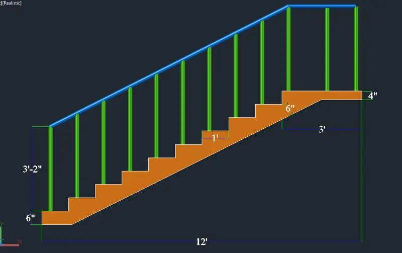
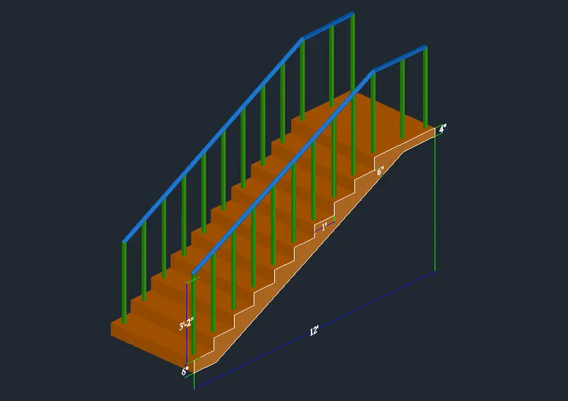
AIM:Create the ismoteric 3d view of a stair with railing as shown in the plan and elevation. Assume the size of the balustrades and the hand rails.
PROCEDURE:
- To create the plan of the stairs
- create the angle
- make it region
- Press/Pull
- Create the handrails
STEP1
- Go to the right side view
- Create the side view of stairs
Command:LINE
- Draw vertical line of 6" //For the riser
- Draw horizontal line of 1' //For the tread
STEP2
Command:COPY
- Select the tread and riser
- Select the start of the riser as basepoint //Basepoint to copy
- TYpe "A" for the array command //To copy multiple at a time
- Enter the value of array 10 //For 10 copies
- select the end of the tread to copy
STEP3
Command:LINE
- Extend the line of the last tread landing to 3'
- Drop a vertical line down of 4"
- Draw a line joining points of tread and riser intersection //To provide the base slab
Command:OFFSET
- Take offset of the line of base slab of 6"
//Join the line of the offset of the bse slab and base of tread of first and last landing
STEP4
Command:PRESS/PULL
- Go to isometric view and shaded region
- Selectt the region between the stairs and give width of 4' //For the stairs width
STEP5
Command:CIRCLE
- Create a circle of Radius of 1" on the tread of first step //For the handrails
Command:PRESSPULL
- Select the circle on the tread and give height of 3'2" //height of handrails
STEP6
Command:COPY
- Select the handrail
- A for array command and enter 10 //For making 10 copies
- "F" for fit and select at the 10 step //To place handrails at equal distance of the steps
STEP7
Command:PLINE
- Select the last handrail top center and first handrail top //To comnnect the lines for baluster
Command:SWEEP
- Create a circle of 1" radius
- select the radius annd then selectt the line //To sweep the circle on the polyline path
STEP8
Commnad:MIRROR
- Select the handrails and handrest of the stairs
- selectt he midpoint of the stairs //For the mirror axis
- draw the mouse down for mirror it and enter "n" //To not delet the original reference
Command:LAYER
- Create layers of name dimensions,walls .windows,panels etc
- provide different colours to them //It ease in distinguishing the object
Command:DIMLINEAR
- Select the two point between which u want to give dimensions //Give the dimesion wherever required
RESULT:
4.
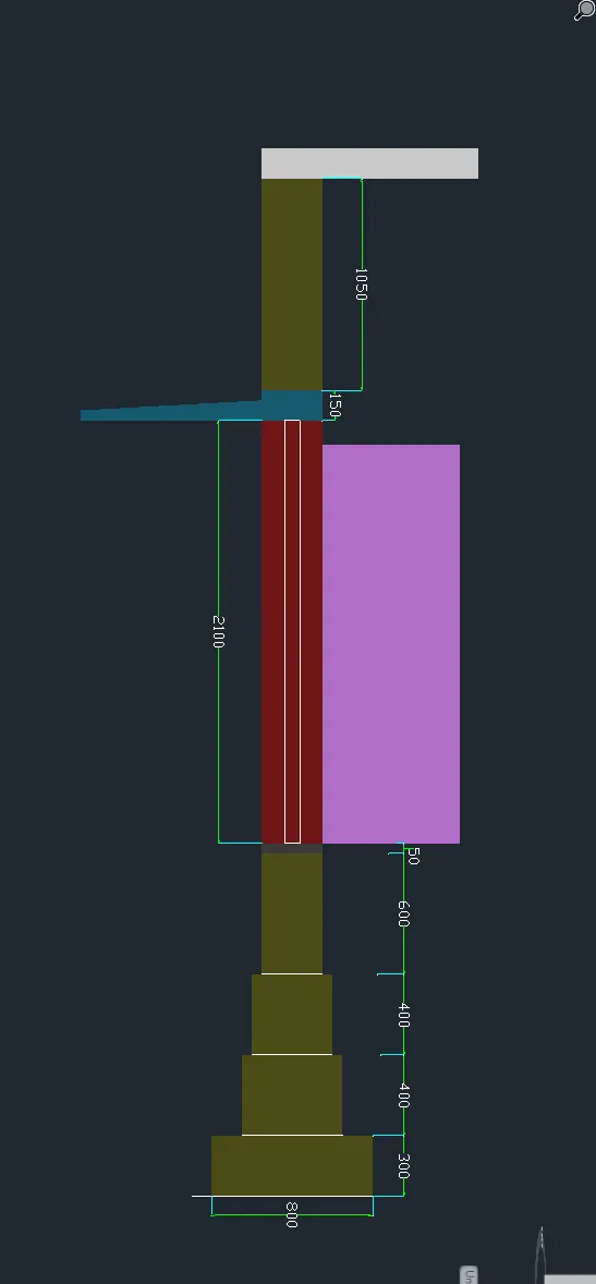
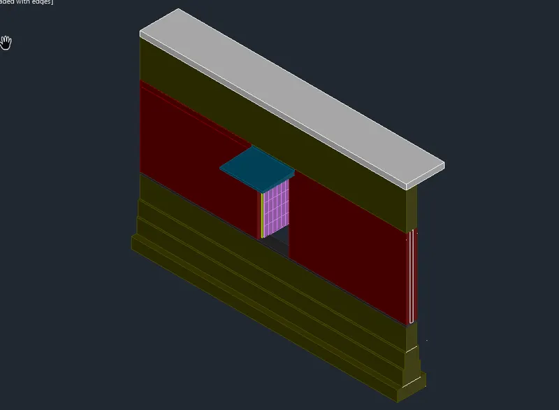
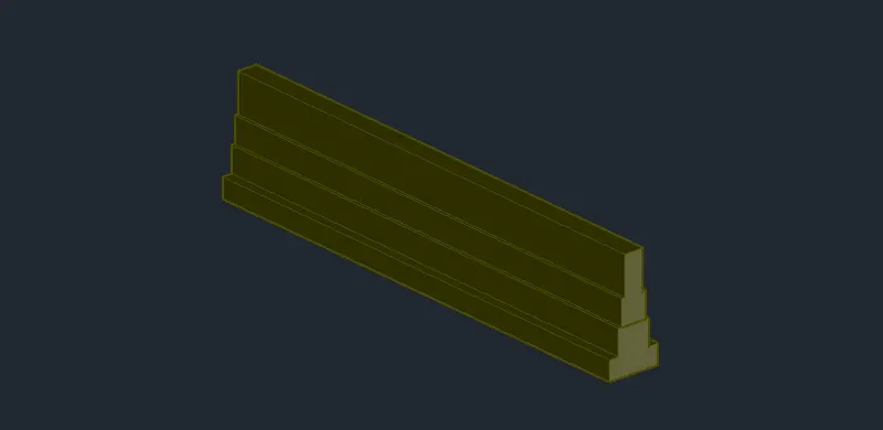
AIM:Create the 3D view of a Wall with spread footing . Create the Door opening only. Assume the size of the parpaet and the coping. See the plans and elevation for the details. Also, create a rendered view of the model with materials as of your choice.
PROCEDURE:
- To create the plan of the wall
- create isometric section
- using Press/Pull
- creating box for foundation
STEP1
- Go to isometric view
Command:BOX
- Create a base rectangle of 800x7500 //For the base slab
- give the height of 300 in z
- Create a rectangle of 500x7500
- Give height of 400mm in Z axis //For the 1nd step of footing
- Create a rectangle of 400x7500
- Give height of 400mm in Z axis //For the 2nd step of footing
- Create a rectangle of 300x7500
- Give height of 600mm in Z axis //For the 3rd step of footing
- Create a rectangle of 300x7500
- Give height of 50mm in Z axis //For the clearance of footing from the wall start
- Create a rectangle of 300x7500
- Give height of 2100mm in Z axis //For the wall
STEP2
Command:RECTANGLE
- Go to side view
- create a rectangle of 300x150
Command:LINE
- From the edge of the rectangle draw horizontal line of 900mm //For thr chhajja projection
- Go 50mm above
- Go to (@900,50) to join the edgse of door //For the elevation of chhajja
Command:TRIM
- TRIm the line between the chhajja and the rectangle base walls
STEP3
Command:PRESS/PULL
- Go to isometric view
- select the chhajja projection
- give width of 1300mm
Command:COPY
- Select the chhajja and paste it at the center of the wall //At 2100mm on Z axis from the floor
STEP4
Command:BOX //FOR MAKING DOOR
- Create a bse of 80x25
- Give height of 2100mm //For the lintel of the doors
Command:MIRROR
- Select the lintel
- select the midpoint of the door(450mm) //450mm from the side of doors
- Mirror it on the other side
Command:LINE
- Draw a line of 20mm hinge
- and perpendicular line to it of 820mm
Command:PRESS/PULL
- Select the line of the door made above //To make the door
- PUll in Z axis of height of 2100mm
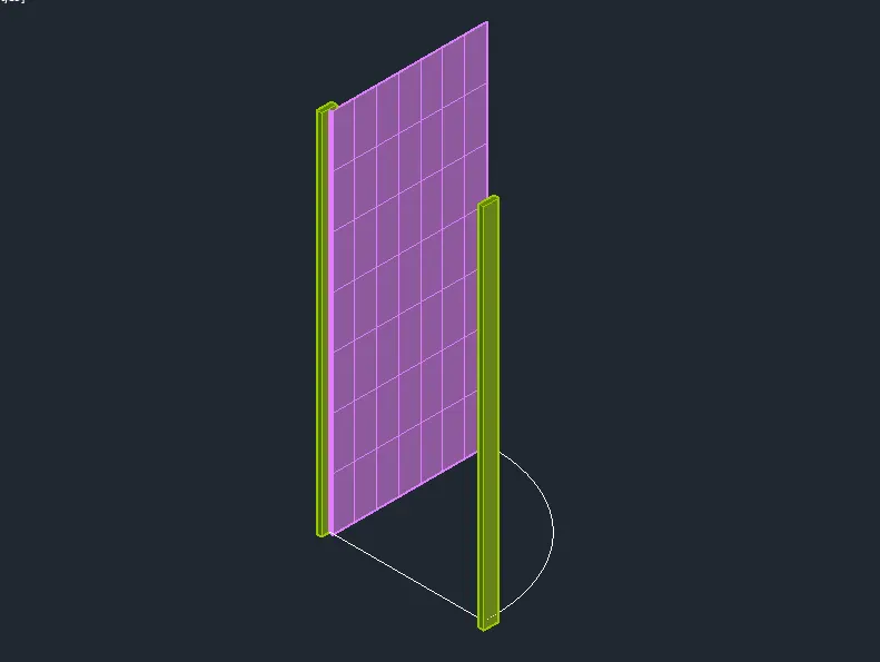
STEP5
Command:COPY
- Copy the door and paste it at the wall
- Using chhajja center as basepoint
- place the door at the wall
Command:SUBTRACT
- Select the object //From which u want to subtract
- Select the object u want to subtract //Select the door
- Click enter
//Repeat the copy command to copy the door on the open space on the wall
STEP6
Command:LAYER
- Create layers of name dimensions,walls .doors, lintels,chhajja etc
- provide different colours to them //It ease in distinguishing the object
Command:DIMLINEAR
- Go to side view
- Select the two point between which u want to give dimensions //Give the dimesion wherever required
RESULT: