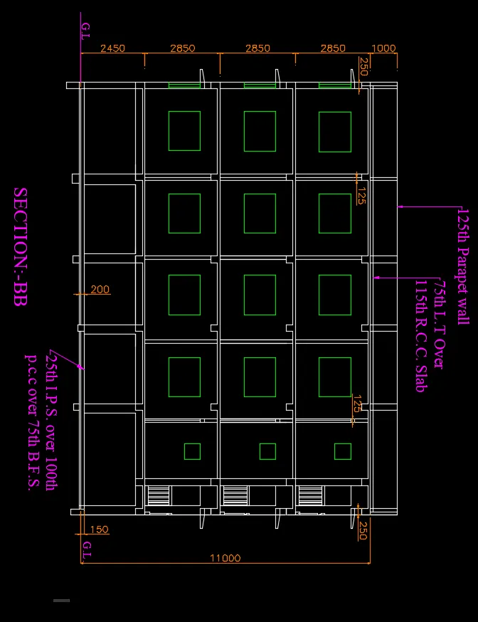
Creating a Layout, Section and Elevation with dimensions using AutoCad
1.
AIM: Create the Plan and Sections as shown in the Figures. Use proper dimension techniques and dimension styles to document the project.
Procedure:
STEP1
Click on insert tab and go to attach and select the files as per the challenge.
Command:SC
SCALE command is used to scale the reference file into the dimension size given in the drawing(selct the object and click Reference,select two point and enter the actual dimension given in the drawing).
STEP2
Command:XL
XLINE,This command is used to draw the refernce line form the reference file and(both vertically and horizonatlly)
Draw a vertical line for the left boundary .
Command:O
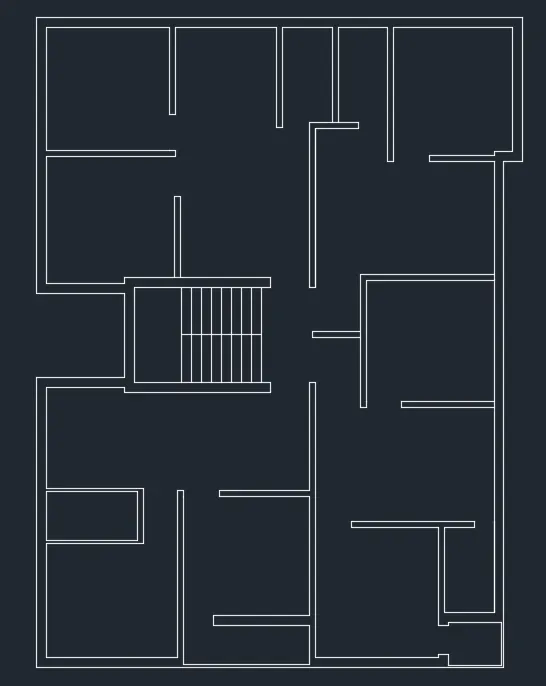
OFFSET,take offset of 230mm horizontally and vertically for the exterior walls
Command:O
OFFSET,take offset of the required dimension 3100mm size both from the vertical and horizontal line //From the top left corner
Command:O
OFFSET,take offset of 150mm horizontally and vertically for the interior walls
STEP3
Command:TR
TRIM, Trim the extra lines not required from the drawing
Command:O
OFFSET, Take the offset of 2550mm and 2525mm vertical line and horizontal line respectively.
Command:O
OFFSET,take offset of 150mm for the interior walls
//Similarly follow the steps as above to draw the walls of the plan.
STEP4
Command:O //Making the stairs
OFFSET,Take offset of 1200mm from the wall of the stairs // Space for the landing
Command:CO
COPY, the vertical line of the landing and selcet the basepoint->The got to "Array" and enter the number of steps.
now seletc the horizontal line parellel to the landing at a distance of 250mm.
STEP5
Command: LA
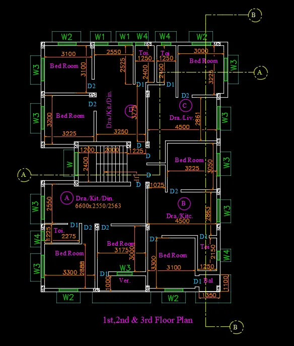
LAYER, Create the layer of windows,doors,dimesions,sections and Texts adn provide the colours as per suitablility.
Command: _ STYLE
To change the text style and height for the drawing //Text Height =300
Command:DIMSTYLE
Used to modify the dimension style for the drawing and text styles //Dimension Text Height=300
//Type the text using Multiline ,Angle (as per the requirement ) at the required roomsand windows by using the layers.
Command:DIMLINEAR
select the points of which u want ot show the dimension and adjust according to the space.
STEP6
Command:XL
XLINE,This command is used to draw the refernce line form the above drawing and(vertically)
Draw a verttical line for the left and right extent of the plan
Command:OFFSET
To Take th offset for the width of the wall for the stairs landing and form the right extent of the walls for exterior walls
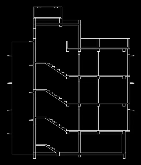
Command:LINE //To make the stairs
Make a vertical line of 148mm and horizontal of 250mm for the stairs riser and tread.
STEP7
Command:MIRROR
Select the object (the stairs) and select the baseline and enter "N" for not delecting the refernce
Command:COPY
Copy the tread and riser and select the base point,Use array and enter the number of stairs.
Copy the stairs on their location for the floor
STEP8
Command:DIMSTYLE
Used to modify the dimension style for the drawing and text styles //Dimension Text Heuught=300
//Type the text using Multiline ,Angle (as per the requirement ) at the required roomsand windows by using the layers.
Command:DIMLINEAR
select the points of which u want ot show the dimension and adjust according to the space.
Command: _mleader
Specify leader arrowhead location and type the text required
Command: _text
Type th Text as required in the places of elevations
Command:Line
Draw a vertical dotted line for showing the changes in section line
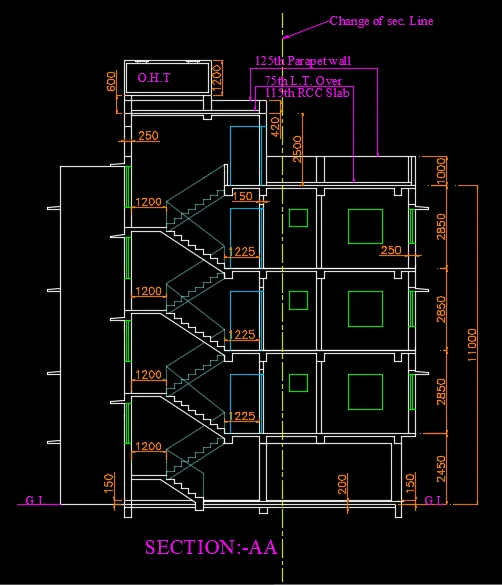
STEP9
Command:XLINE
Use Infinite line to take th refernce of the drawing from the plan on top and down side //Tolimit the width of the plan
Again use the XLINE to draw a vertical line for the base of the plan
Command:OFFSET
Take the offset equal to the height of the building //To limit the height of the building
Command:OFFSET
Take 200mm offset from both the vertocal line inwards direction for the floors thickness
STEP10
Command:XLINE
extend the xline in the drawin to take the refercnce point from the plan
Command:TRIM
Trim the xtra lines of the XLINE going beyond the line
STEP11
Command:COPY
Copy one floor and paste it for the next two floors down below.
Command: _text
Type th text as reuired in the drawing with according to the angle //Text Height 300
Command:DIMLINEAR
select the points of which u want ot show the dimension and adjust according to the space.
Command: _mleader
Specify leader arrowhead location and type the text required