Creating various 3D Models like Furniture, Footing, Girder, Column drop with panel and Gable Wall in AutoCad
1.
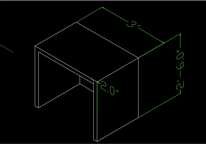
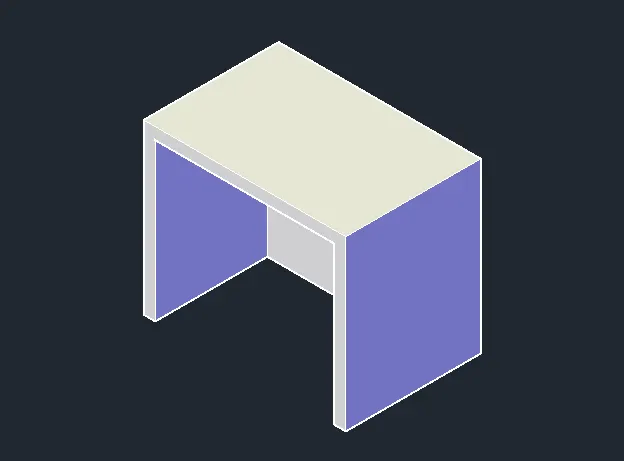
AIM: Create a 3D Furniture element as shown in the Figure. Assume dimensions which are missing
Procedure:
- Switch to 3d modelling
- create the surface
- taking offsets
- creating region
- doing 3dface and hide.
STEP1
- Go to workspace switching
- Select 3d modelling //To switch 3d space
STEP2
Command:LINE //SW Isometric view
- Create a line of 2'6" on z axis
- draw a line of 3' on Y axis
Command:COPY
- copy the 3' line and paste at the base
- Copy the 2'6" line and paste at left side //For making thr back face of rectangle
STEP3
Command:LINE
- draw a line of 2' on -ve x axis on both the side of the rectangle face.
- Connect the line between two
Command:OFFSET
- Select the front face lines and offset of 2"
- Select every line of front face and offset //To show the thickness of the object
STEP4
Command:REGION
- Select all the object and click enter. //All object will turn into region
Command:3DFACE
- Select 4point of any side of face //To hide the lines behind it
- Click enter //To make it look like 3D
Command:HIDE
- Type "HI" Click enter //The face will face a surface over the 4points selected
STEP5Command:LAYER
- Create layers of Name DIMENSION ,give colours to it
Command:FACE
- Move the UCS axis to the face whose dimension u want to see //It automatically fixes xy axis on the surface u selected
Command:DIMLINEAR
- Select two points between which u want to show dimension
RESULT:
2.
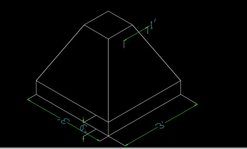
AIM:Create the 3d Model of an Isolated footing as shown in Figure.
Procedure:
- Switch to 3d modelling
- create the rectangle surface
- taking offsets
- create circle
- doing 3dface and hide.
STEP1
- Go to workspace switching
- Select 3d modelling //To switch 3d space
STEP2
Command:RECTANGLE
- Go to top view
- Create a rectangle of 3'x3' on xy plane //For the base
Command:COPY
- Go to isometric view
- Copy the rectangle
- Select a base point
- paste it 6" above on Z axis from the base point //paste at (0,0,6")
STEP3
Command:RECTANGLE
- Go to top view
- Create a rectangle of 1'x1' on XY plane
Command:MOVE
- change into left/right view
- Select the 1'x1' rectangle and move 2'6" in the z direction //to provide height to the object
Command:LINE
- Change into Isometric view
- JOin the edges of 3'x3' and 1'x1' rectangle //To makeit 3d object
STEP4
Command:3DFACE
- Select the 4 point of the front face //To make it as a 3D face
- CLick OK
Command:HIDE
- Type "HI" Click enter //The face will face a surface over the 4points selected
STEP5
Command:LAYER
- Create layers of Name DIMENSION ,give colours to it
Command:FACE
- Move the UCS axis to the face whose dimension u want to see //It automatically fixes xy axis on the surface u selected
Command:DIMLINEAR
- Select two points between which u want to show dimension
RESULT:
3.
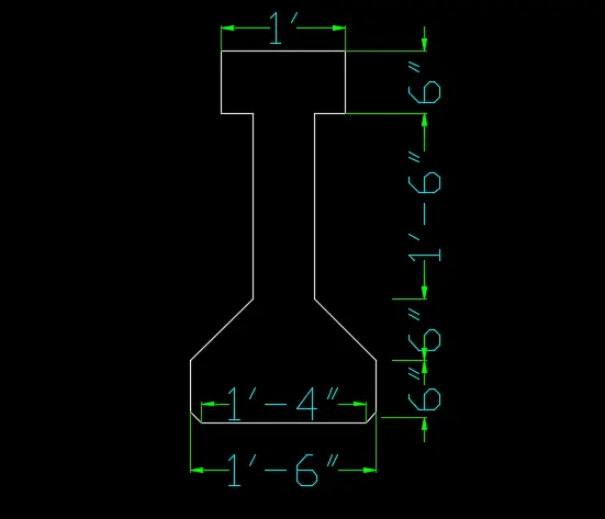
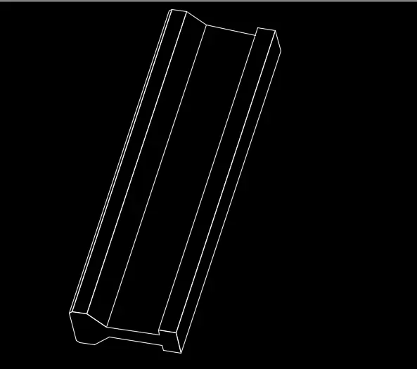
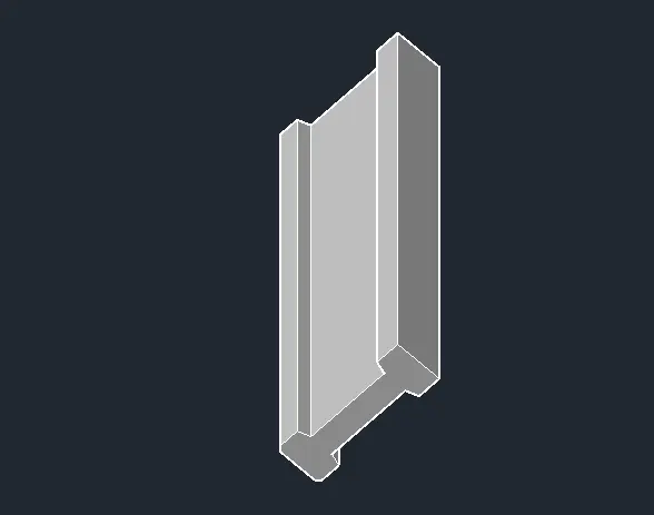
AIM: Create the 3D view of the AASTHO Type Girder
Procedure:
- Switch to 3d modelling
- create the rectangle surface
- Connecting lines
- Mirror te object
- doing 3dface and hide
STEP1
- Go to workspace switching
- Select 3d modelling //To switch 3d space
STEP2
Command:LINE
- Go to top view
- Draw a line of 1' horizontal towards right //From the top left
- draw 6" line downwards
- 3" line towards left
- 1'6" downwards
STEP3
Command:OFFSET
- Select the top horizontal line //Top head of the line
- offset downwards for about 3' //For lower bse line
- Take the base line offset of 1" upwards
- Take 6" offset of that previous taken line upwards
Command:LINE
- connect the lines of the step2 to step3
- For the base line increase the length of line from 1' to 1'6" /To make the base foting of rails
//Increase the length of line the foot of rail to about 1'6"
STEP4
Command:ERASE
- select the line from the inside and erase it
Command:MIRROR
- Select the right side of the lines //Made from the above steps
- And mirror it to the left side
STEP5
Command:LINE
- Go to isometric view
- Draw a line from the center of the plan of rail of 10' height //Perpendicular to the plan
Command:SWEEP
- Select the object u want to sweep //The plan of rail
- Select the path which u want to sweep //The perpendicular line
STEP6
Command:3DFACE
- Select the 4 point of the front face //To make it as a 3D face
- CLick OK
Command:HIDE
- Type "HI" Click enter //The face will face a surface over the 4points selected
STEP7
Command:LAYER
- Create layers of Name DIMENSION ,give colours to it
Command:FACE
- Move the UCS axis to the face whose dimension u want to see //It automatically fixes xy axis on the surface u selected
Command:DIMLINEAR
- Select two points between which u want to show dimension
RESULT:
4.
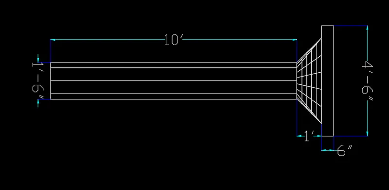
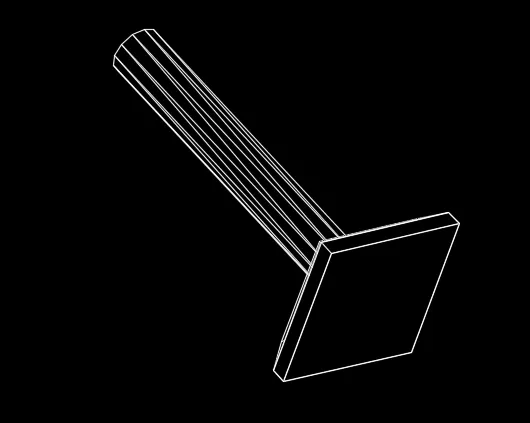
AIM:Create a 3d Model of a drop column with panel as shown in section and isometric view
Procedure:
- Switch to 3d modelling
- create the rectangle surface
- taking offsets
- create circle
- doing 3dface and hide
STEP1 //For the top view
Command:RECTANGLE
- Go to top view
- Create a rectangle of sides 4'6x4'6 //For the lowest base
- From the center create a rectangel of 3'6x3'6 //For the base rectangle
Command:CIRCLE
- From the center of the above rectangle draw 9"circle //For the column start base
STEP2
Command:COPY
- Go to ISOMETRIC view
- Select the circle
- Copy the circle at 1'6" on the z axis To take it above the height
- Copy the circle again at 10' on the Z axis line //For the column height
Command:ERASE
- Erase the lowest circle at the base
STEP3
Command:COPY
- Select the rectangle 4'6x4'6
- copy it above at 6" distance at z axis //For the width of base
Command:MOVE
- Select the rectangle 3'6x3'6 //From the bottonm base
- select center as basepoint
- Move at distance of 1' on the Z Axis above. //For column to base joint
Command:LINE
- Join the edges of the rectange to the smaller rectangle //Join from all the sides
- Join the center of the two circles
STEP4
Command:SWEEP
- Select the object u want to sweep //The circle at the top
- The path u want to sweep the object //The perpendicular line between two circles
Command:LOFT
- Select the 3'6x3'6 rectangle
- select the circle ,click enter //The rectangle and circle will have smooth transition surface
STEP5
Command:3DFACE
- Select the 4 point of the front face //To make it as a 3D face
- CLick OK
Command:HIDE
- Type "HI" Click enter //The face will face a surface over the 4points selected
STEP6
Command:LAYER
- Create layers of Name DIMENSION ,give colours to it
Command:FACE
- Move the UCS axis to the face whose dimension u want to see //It automatically fixes xy axis on the surface u selected
Command:DIMLINEAR
- Select two points between which u want to show dimension
RESULT:
5.
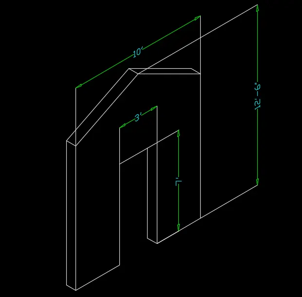
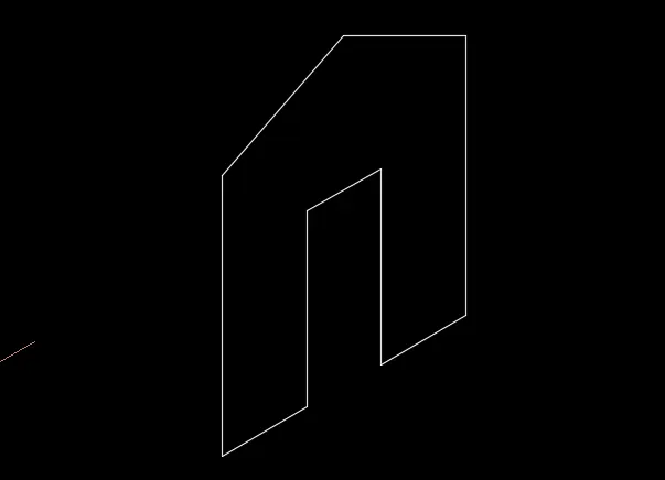
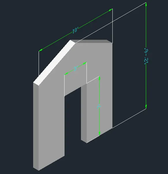
AIM:Create the 3d model of a wall as shown in Figure. Consider wall thickness as 9”.
Procedure:
- Switch to 3d modelling
- create the edges using line command
- mirror the side edges
- Extrude surface
- doing 3dface and hide
STEP1
Command:LINE
- Go to Isometric view
- Draw line of 1'6" on X axis (+ve direction) //Starting from middle of the door anticlock direction
- Go 7' up in Z axis (-ve direction) //For the door height
- Go 3'6" in +ve X axis
- Draw line of 10' towards +ve Z axis //For height of house
- Draw a line at coordinate [-5',0,2'6"] //For the mid arch of the house
STEP2
Command:MIRROR
- Select the right half drawing //Activate the Orhto mode for accuracy
- Select the mirror axis point //Center of the door as mirror axis
- pull the cursor down and click ok
- enter "n" //To not delete the referal object
STEP3
Command:JOIN
- Select the drawing
- click enter //It'll join all the lines of the drawing as one
Command:REGION
- Select the surface u joined in the aboce step
- Click enter //It'll make the surface of that drawing
STEP4
Command:EXTRUDE
- Go to shaded region
- select the region surface
- Extrude it at 9" width in Y axis //It'll amke the surface in to 3d solid
STEP5
Command:3DFACE
- Go to 2DWIREFRAME
- Select the 4 edges in the front side //Select the last point after making it invisible
- CLick Enter
Command:HIDE
- Type "HI" and click enter //It'll hide the lines appearing behind the front surface
STEP6
Command:LAYER
- Create layers of Name DIMENSION ,give colours to it
Command:FACE
- Move the UCS axis to the face whose dimension u want to see //It automatically fixes xy axis on the surface u selected
Command:DIMLINEAR
RESULT: