Conceptual design of a building with columns and shear walls
1:
AIM: The building shown, 20 × 35 m in plan, has columns on a 5 × 5 m grid and shear walls (with dimensions shown in m, 250 mm in thickness) in three alternative arrangements, (a), (b), (c), all with the same total cross-sectional area of the shear walls. Compare the three alternatives, taking into account the restraint of floor shrinkage, the lateral stiffness and the torsional one with respect to the vertical axis, the vertical reinforcement required for the same total flexural capacity at the base, the static eccentricity, the system’s redundancy, foundation systems, architectural constraints etc.
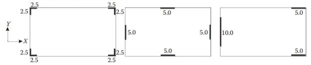
ANSWER:
| TYPE A | TYPE B | TYPE C | |
| Floor restraint | The four shear walls are symmetrically placed and uniform in size and shape.This possess good control of shrinkage. | Only the edges are walls are provided with the shear walls and corners are prone to shortening and shrinkage with frame systems. | In both principal direction, the floor is not enclosed with RC walls on bith the sides.SO this floor will have more shrinkage. |
| Lateral stiffness |
During earthquake the direction of seismic force will be fo both lateral direction,BUt the walls in this type is not in the X & Y direction,But it is in diagonal direction,So it posses less stiffness. |
SInce the RC walls are provided in both the lateral lateral axis direction .so it will provide good lateral stiffness against seismic forces. |
The RC walls systwms are are effective and and stiff in X diection because of wall present in both sides,But not towards Y direction because the walls in only one side and the other side is not stiff. |
| Torsion |
Center of mass and center of stiffness will coincide ,therefore less prone to torsion. |
Center of mass and center of stiffness will coincide therefore less torsion. |
Center of mass and center of stiffness does not coincide due to assymetrical placement of RC walls,therefore prone to torsion |
| Vertical reinforcement |
This will experience lesser lateral force ,therefore less vertical reinforcement is required |
This system will take loads of eithers principle axis therefore the reinforcement will be more than the previous system. |
The walls is so assymetrically arranged,therefore these will experience more lateral and torsional load,.It will require huge amount of reinforcement. |
| Static eccentricity |
The system is centric with respect to mass stiffness comparison |
This system is centric with mass stiffness comparison |
More eccentric with respect ot mass stiffness |
| Redundency |
Since the RC wals is less effective ,therefore Frame will take the load resisting system |
Walls are effective inthis case and mirror with right angle and possess good redundency |
Load is more at one sie of the structure therefore less redndant |
|
Architectural Constraints |
Architecturally very effective and doesn't block the view |
Architecturally may be not good as it blocks the major lateral side of the builidngs | Left side of building is blocked ,right side is architecturally good |
2:
AIM: Discuss the suitability for earthquake resistance of the moment resisting framing plan of a three-storey building depicted here (cross-sectional dimensions in cm), the eccentricity of the centre of mass (as centroid of floor plan) to the centre of stiffness (from the moments of inertia of the columns) are shown. Suggest an alternative. Also, is there torsional flexibility? Are the two fundamental translational modes of vibration larger than the fundamental torsional mode of vibration. Discuss qualitatively.
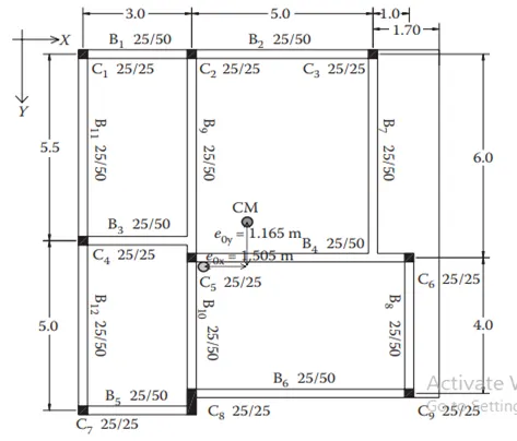
ANSWERS: All the frames are not continued from column to column which is not acceptable for earthquake resistant house designs.The lack of redundancy and eccentricity may cause failure of the building during seismic conditions. Eventhough it is just 3 storey building it will affect the structure due to the inappropriate design of transferring the load to the ground.
Column C5,C8 ,C6 are not in continuation with the other columns which cause in the interruption in the proper transfer of lateral load .
Improvised plan of the above drawing after giving proper continuity to the beams .
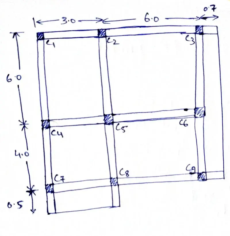
The center of mass and stiffness are not coinciding therefore,the builidng will experience torsional flexibility along vertical axis.
The structural floor is not effective in transferring of vertical loads due to improper beam to beam connections.The building structure is poor to sustain the lateral seismic loads.
3:
AIM: A multi-storey building with basement, with a quadrilateral (non symmetrical floor plan) plan as, has interior columns in an irregular (not in a grid) pattern in plan that serves architectural and functional considerations. Partition walls and interior beams supporting the slab have different layout in different stories. However, there is no constraint to the type, location and size of the lateral force resisting components and sub-systems on the perimeter. Proposals are to be made and justified for the choice of the lateral-load-resisting system and its foundation.
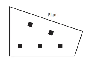
ANSWERS:As per plan dimensions the center of mass will reside on the left side portion of the plan. As the area of the plan is larger on the left portion.So we position lateral loads in such a way their stiffness center should come near the center of mass to avoid torsional rigidity.
since the floor is unsymmetrical and irregular quadrilatteral,the influence of X direction also effect the Y direction vice versal.So a bi lateral resisting system should be added to resist the seismic forces. Therefore L shaped walls is to be made at the corners of the plan to resist the lateral seismic forces.