Project - 2 - Meshing on the suspension Assembly
Aim - For the given assembly, check for the geometrical errors and mesh with the given element Quality criteria. After meshing the component the thickness has to be assigned for mid surfaces. Use tetra elements to model non-uniform thickness components. Also use Appropriate connections to connect the component as suggested (Use PBAR elements to model suspension spring). At last perform Symmetry command to reflect the half finished model to the other side.
Procedure -Import the model from the downloaded file.
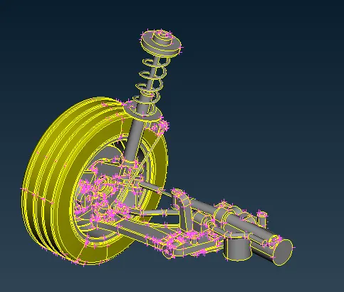
The component seems to be as shown in above. The basic procedure needs to be done as geometrical checks.
Fit the model in to the screen and do the checks for the component.
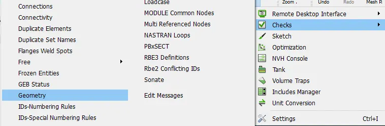
Do the checks for the perticular component and execute.
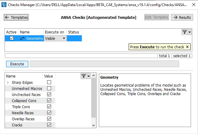
It will shows the issues and fix that issues and by using the autofix.
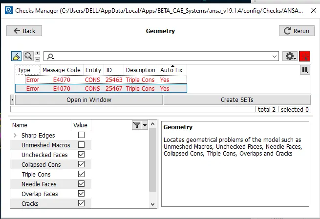
For this assembly component make it seperate PID for individual component for shown component.
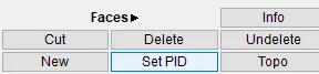
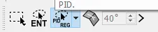
Select the PID and select the PID region.
Set the new PID for the individually for all the parts.
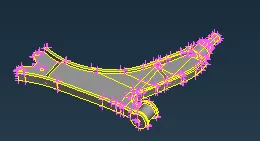
For all component the set the PID for all the individually by below shown.
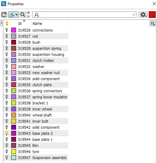
Set PID for all the components as shown in below.
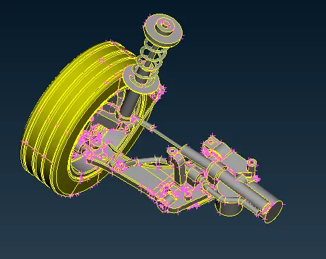
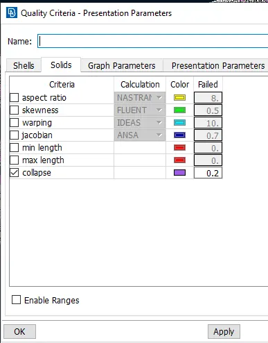
Start doing meshing for the individual component for the all component with the specific quality criteria and mesh parameters given tyre and rim
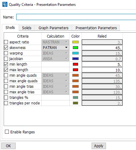
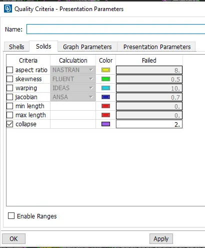
The below shown figure the mesh parameters for the component.
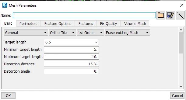
After the assigning the all parameters start doing the meshing.
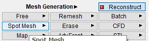
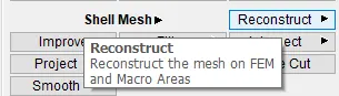
After meshing with the reconstruct and smooth option to get better mesh flow.
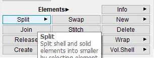
If there is creating the more tria and elimited that trai by using the split and swap option.
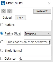
Adjest the failed element edges can be fix by using the move option.
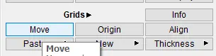
In move option choose the perims slide for specific feature boundary.
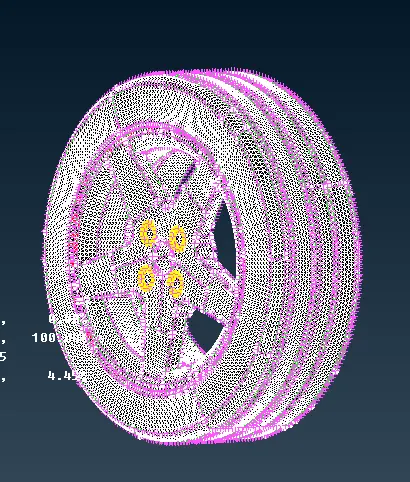
The below shown figure after meshing it seems like below shown in figure.
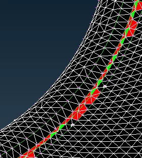
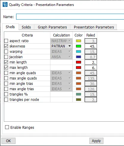
Similarly for other then the tyre and rim components have different mesh and quality parameters file.
After meshing the component has seems to be below shown.
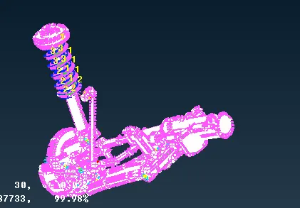
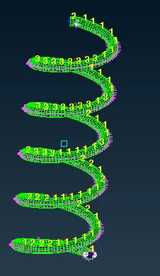
For suspention spring create the PSOLID elements(1D bar elements).
The link is - https://skill-lync.com/knowledgebase/how-to-represent-a-spring-with-1d-bar-element
For sheet metal component extract the mid surafce for the component.
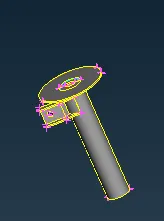
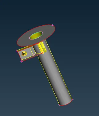
Assign the mesh and quality parameters for the sheet metal components.
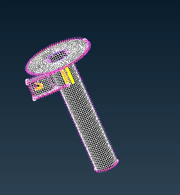
For diploid the connections for the compoenents when ever its need.
First create the bolt connections by creating the COG for the component.
The below shown crated the 3D point as shown in below.
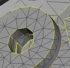
Convert that 3D point in to the bolt.
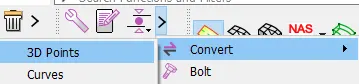
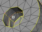
Select that 3D point and select the bolt as connection type.
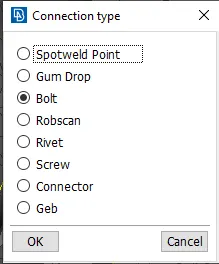
The below shown the bolt connections as shown in below.
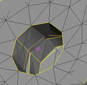
Select the cluster RBE2 and using by many nodes.
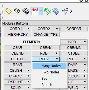
Select the edge nodes and diploid the RBE2 connections as shown in below.
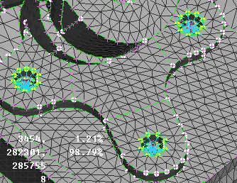
For the seam weld connections create the curve. and convert that curv in to the seam line.
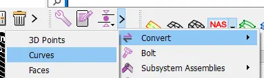
After creating the seam line and select the connection manager.
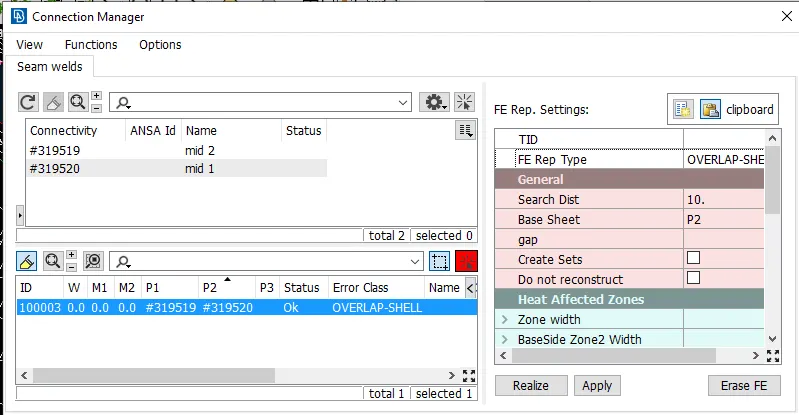
The diploid the seam weld for the both the sheet metal component as shown in below.
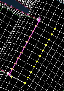
Similarly for the component has to be make 1D element connections by using the RBE 2
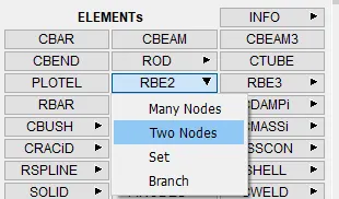
Select by two nodes and the crate the single connections for the component.
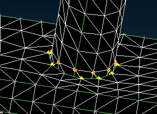
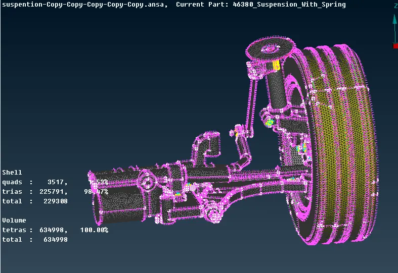
After these all the connections, meshing and 3D meshing the final component is seems to be below shown in figure.
Conclusion
By performing mesh for this assembly component needs to be the understand how to make assembly type of components to be properly. Along with proper set the proper PID for the components.