Assignment 5-RADIOSS Interfaces & Study of Effect of Notches Challenge
Aim
1)To perform meshing for the bumper component.
2)The Radioss solver to interface between the surfaces with introducing the notches in the different type of cases.
Objectives
- Create the mesh for the bump assembly by using the mesh element size as 6mm.
- To perform the differnt type of cases in crash tube model.
- Effect of nothes introducing to crash tube model.
- After simulation plot the graph for I.E, K.E, T.E, C.E with the RWALL forces with the resultant forces.
- By using the h3d file study with the element variation in the animation with mode of von mises.
- Make the conclusion with the result.
Introduction
Interface / Contact Modeling
The explicit analysis method is used to solves advanced dynamic contact issues (boundary condition with the nonlinearity). To presize in the modeling of contact interfaces is properly capture contact between 2 body. RADIOSS has the have the many application in the industry. Its make the equal amount of contact on slave to master a sizable amount of contact sorts appropriate for several applications. In RADIOSS associate degree interface model with the slave nodes. The contact will analyse the penitartion over the component in step by step process in several cases. The algorithmic can check the penetration of a slave node with the master section. If penetration is detected the contact is named with either a Penalty or by Lagrange multiplier factor technique.
The Penalty Method
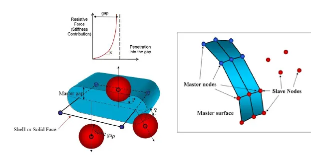
The penalty method is decide on the basis of master and slave nodes with the interface. The contact is only arise between the set of slave nodes and the master nodes in the segments. The master nodes are the decide the type of element on. Spring parts that generate resistive forces as a operate of penetration area unit created between the slave node and its projection. The spring stiffness is mechanically computed consistent with the fabric and property of each master section and slave node. The time step could also be affects the contacts the stiffness. Contact ends once the penetrated node is totally pushed out of the gap.
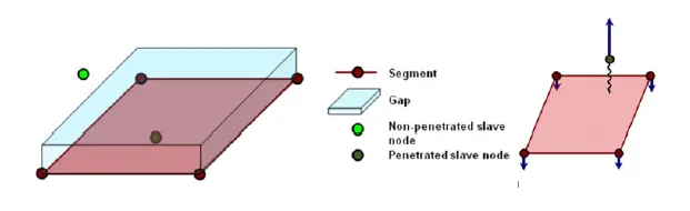
Lagrange Multiplier Method
The penalty methodology, the Lagrange number methodology is solved mathematical and doesn't required physical component to model contact. A system of equations is resolved to account for contact conditions. Therefore, there's no time step collapse for the high interface stiffness, however it takes a lot of computer hardware time to try to to one cycle as new equations got to be resolved by a nonlinear convergent thinker.
Variation in interface are as shown in beow.
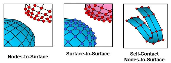
Interface Type 7: Nodes to Surface Contact
The interface of type 7 is used as common interface with it will simulate all kinds of impact between a group of nodes and a master surface. Interface type 7 solves all the issues and limitations oriented with interface type 3 and 5. The seek for the nearest phase is finished via an instantaneous search algorithm; thus, there are not any search limitations and every one doable contacts ar found. Finally, the main advantage of interface type 7 is that the stiffness is not constant and increases with the penetration preventing the node from going through the shell midsurface.
Important Interface Parameters
Igap - Determines how the size of the gap is calculated.
Gapmin - Minimum gap for activation of interface.
Inacti - Action to take if initial penetrations exist.
Istf - Affects how the stiffness of the interface is calculated.
Iform - Friction formulation.
Stmin -Minimum stiffness to use in the interface.
Idel -Update for Deleted Elements Due To Failure.
In gaps there types we are commonly using in interface is shown.
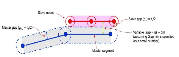
Interface Type 7: Some Gap Definitions

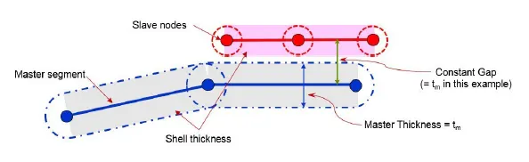

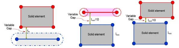
Interface Type 7: For Solid Elements
Interface Type 7: Options For Defining The Gap

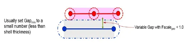
Interface Type 7: Options For Defining The Gap


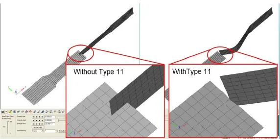
Interface Type 11: Edge to Edge Contact
- This case there is the type of the egde to edge contact will happen only with the 2 interface are touches each other It is finding the and slave edges.
- Interconnect between a master and a slave line. A slave line can connects on one or more master lines. A line can belong to the master and the slave side. It makes the self-impact situation.
- Works similar to Type 7 in terms of Penalty creation, Gap definition and Search method.
. 
Interface Type 19: Combination of Type 7+11
It is mixing of two same TYPE7 interfaces and one TYPE11 interface.
• Commonly assign on the same slave/master surfaces.
• Ii is used in complex contact problems of the such airbag unfolding situations.
• Computationally expensive so only problematic segments should be defined.
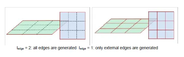
• Edges to edge contact flag Iedge.
Part-1
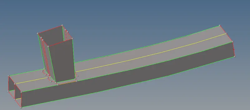
To do the bumper assembly component for meshing is to the geomentrical cleanup initially and after give the target element size will be giving as 6mm.
First step to open the component from the file. Import in to GUI.
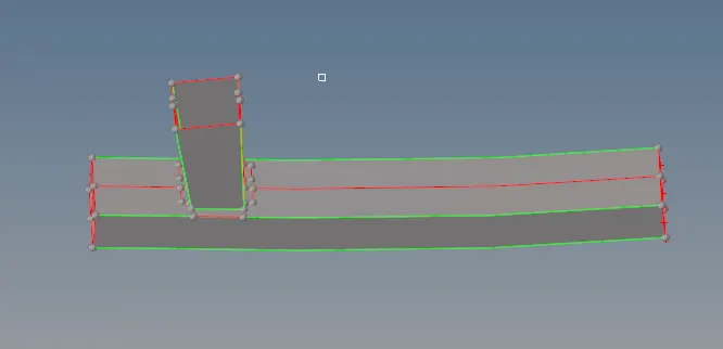
By using the extend command connect the proper surfaces and make the surface is connected.

By using the trim with surface delete the unnecessary surfaces and while intersecting the two surfaces connecting.

After doing the geometrical cleanup do the meshing for the component.
Select the 2D meshing and select the target element as 6mm and mesh type will be mixed and start meshing the component.

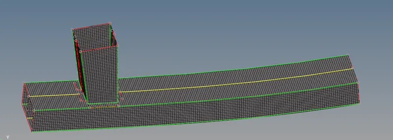
After doing meshing the component should seems to be below shown.
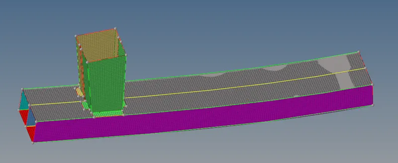
When meshing is completed check for the duplicate and delete that elements. Finally in the wire frame mode component is seems to be
below shown.
Part-2
Case 1 Run the crash tube model as it is.
The given solver deck file will import from the file.
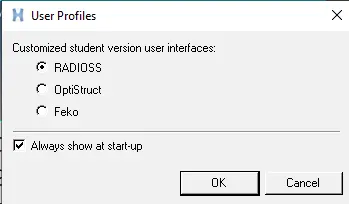
Open the hypermesh and select the profile as radioss
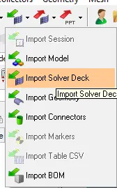
Import the starter file from the solver deck as shown in below and import in to GUI.
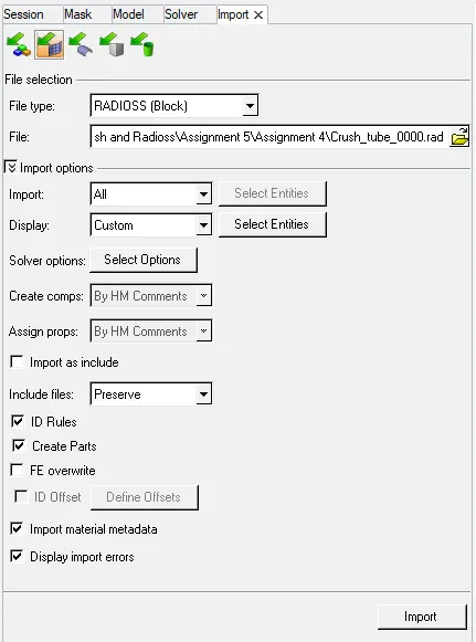
Import the model from the solver deck as the jhohnson _0000.rad. click on import.
The johnson material has been seems to be below shown.
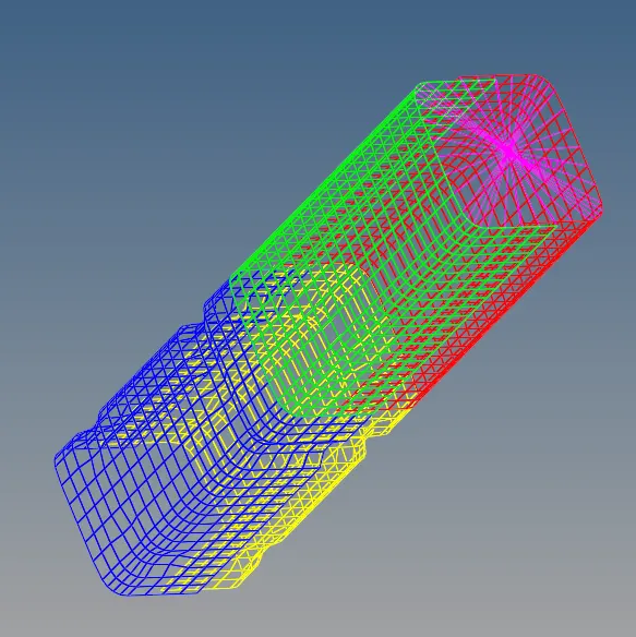
The shaded element ans mesh line command will use.
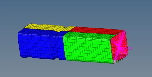
Now the component is seems to be in the right manner.
Similar procedure is to follow to import the compoenent for every case.
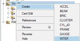
To create the contact forces between the two surfaces and select .
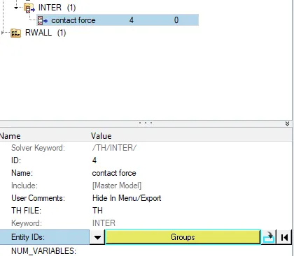
The entity Id has to select the self contact to that and ok.
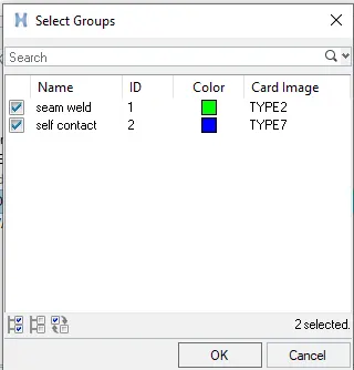
The contact parameter of self contact has been assign.
Select the analysis type as the Radioss.
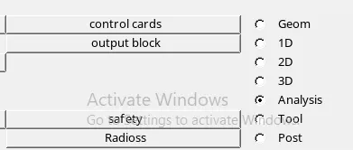
Do the input file and where the file has to be save.
To speed up the simulation mention the -nt 4 and slect the Radioss to start the simulation.

After open the run file of 0001_out file and
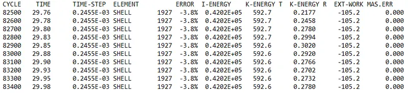
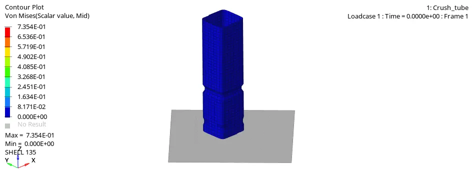
The animation h3d file can run in hypercrash.
Select the file h3d file and apply on screen.

Plot the graphs from the importing the file of T01 and import and apply
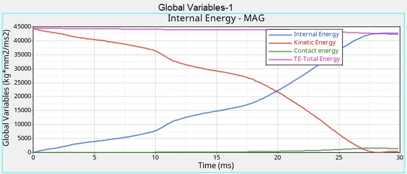
Select the global variables and select the all type of energy has been plotted.

The below shown the global variables of the all energy has been plotted.
As shown in graph with high kinetic energy w.r.t time the graph will decreasing as velocity has been decreases the kinetic energy also gets decreses as shown in below.
The all resultant of all energies has been taken as the total energy has shown in graph.
The internal energy has been initially not have any deformation after some time interval the deformation gets in the mesh model and increase gradually. At reaches the max deformation the internal has been gets constant.
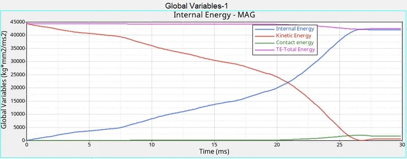
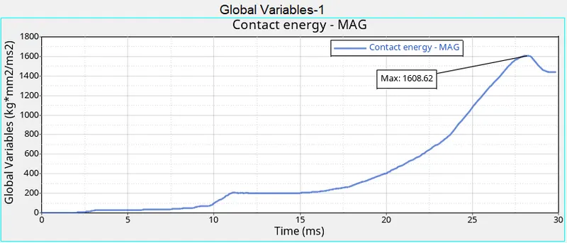
As graph shown the contact energy has been start from the origine because the there is not have the contact between the any elemnts. After have some time interval
it was gradually increases from 20 to 30ms due to the contact energy between the elemnts as shown in below.
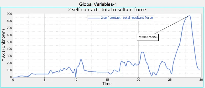
The contact force is to be of the elements are shown in below. when the tube will deformation takes place the the elements are collide with each other. It is due to contact force will increase with respect to time period and some time interval at 25 to 28ms this contact force will gets maximum.
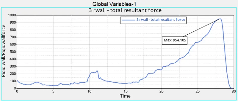
The total resultant is of regid wall forces is increasing initially means the tube have elements get colloids and gradually increasing from the time interval 20 to 28ms.
The collids between the elements have created the increasing force with the colliding action as shown in below.
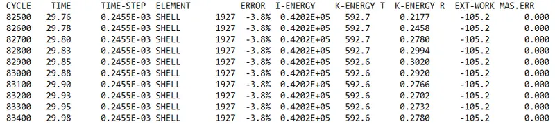
The given results got from the simulation.
Cycle time - 83400
Energy error - -3.8%
Mass error - 0%
Elapsed time = 150.28 s
Case 2 Change the Inacti=6 and run.
After creating the self contact for the element assign the Inacti of 6 in the Type 7 of card image as shown in below.
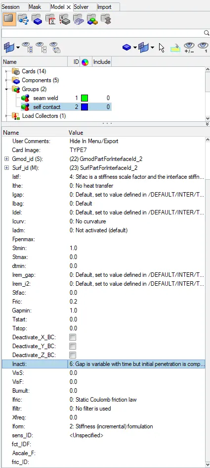
The assigning the Inacti is shown in below.
Inacti - Action to take if initial penetrations exist.

After run the model the results for the post processing results will be as shown in below.
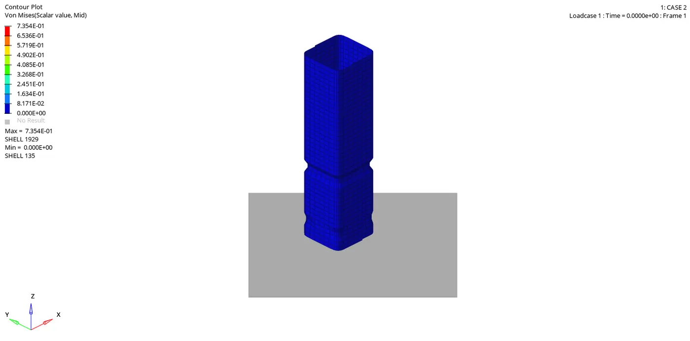
After done the simulation import the file of h3d file and apply on the screen.

The animation file has been shown in below. First base of the deforming and after the tube is fully gets deformed in final stage.
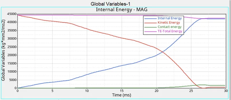
To plot the graph import the T01 file in to the hypergraph and apply.
The below shown the all the energies are plotted here.
- The tube has initially have high kinetic energy and after some time interval the kinetic energy has been decreses as shown in below.
- As initially not have any deformation in the tube so initial energy has been starts from origine. After tube gets deformed with the increasing the graph .
- The total energy has beeen of the total resultant energy has been taking in to count.
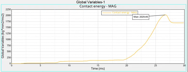
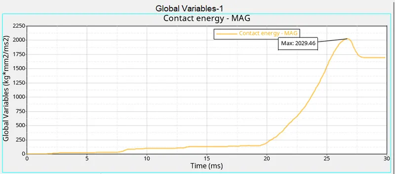
The contact energy has been initially 0 because the not have any deformation in the tube. Gradually graph goes increasing with at time 20 to 30 ms has been increase up to 2029.46 as shown in below.
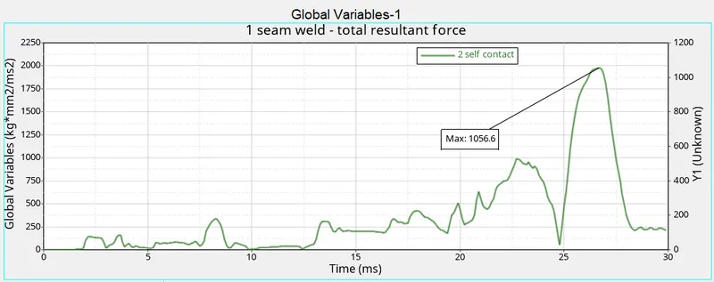
The tube will be of the deformation in the tube the elements were gets self contact or collide with each other. The force to generated in the elements of self contact is of variation is as shown in the below graph.
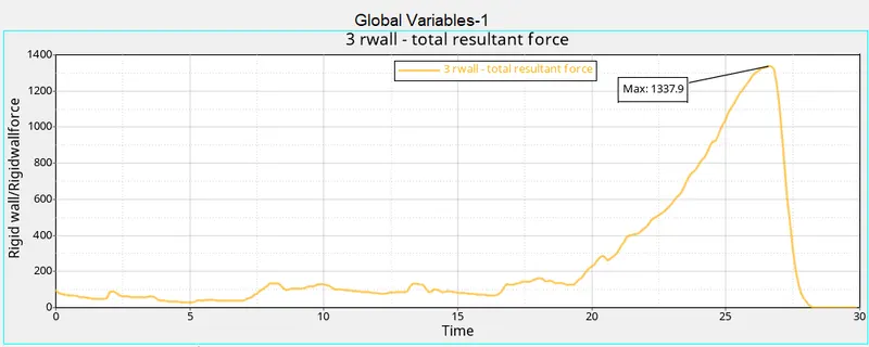
The regid wall force initially force is been applied so in graph it was shown in force. After fluctuating only the regidwall force has been increases and body gets deformed fully it has been stop.
The given results got from the simulation.
Cycle time -83400
Energy error - -3.8%
Mass error - 0%
Elapsed time = 152.13 s
case 3 Create the type 11 contact and run.
After assigning the self contact and the type 11 (Edge to Edge Contact) has been selected.
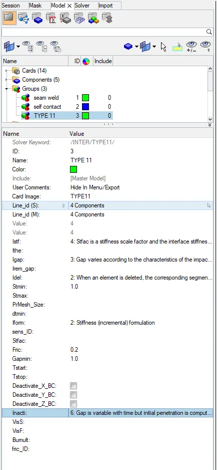
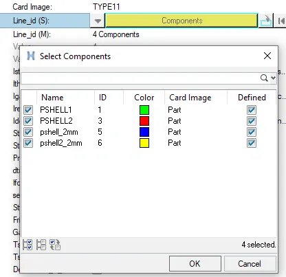
For the 11 type contact Line id has been set and select the tube with 4 component as shown in below.
The entity Id has been select the type 11 and self contact as shown in below.
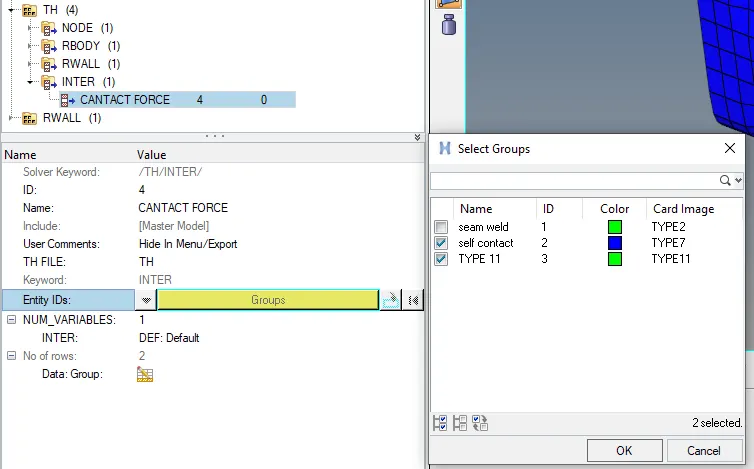
After run the model the results for the post processing results will be as shown in below.
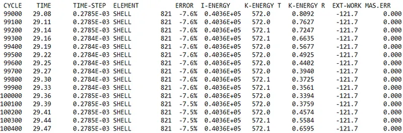

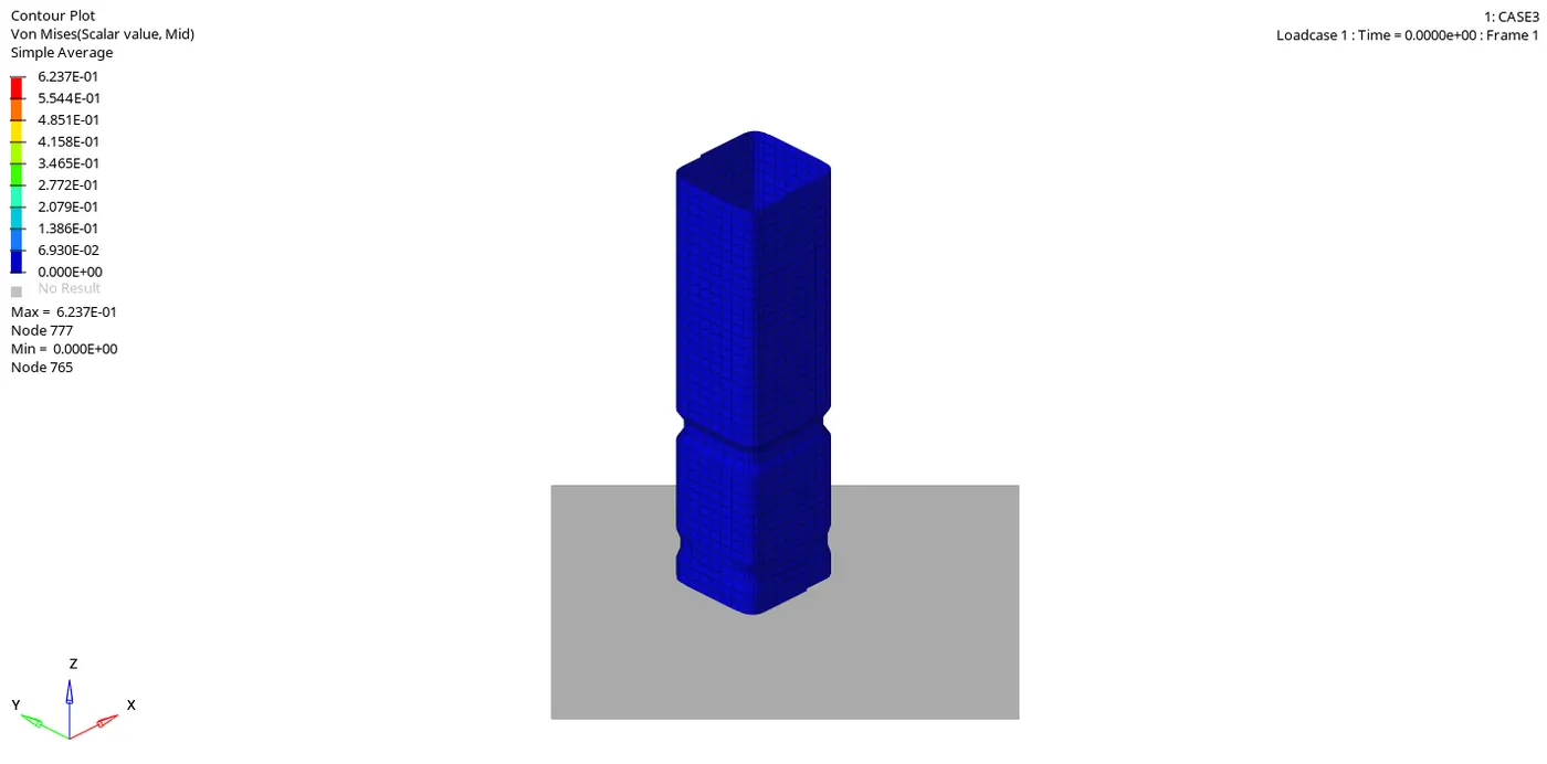
After run the simulation get the results for the case 3. In files get the animation file of h3d and apply.

The animation view has been shown in the below.
The below shown the all the energies are plotted here.
- The tube has initially have high kinetic energy and after some time interval the kinetic energy has been decreses as shown in below.
- As initially not have any deformation in the tube so initial energy has been starts from origine. After tube gets deformed with the increasing the graph .
- The total energy has beeen of the total resultant energy has been taking in to count.
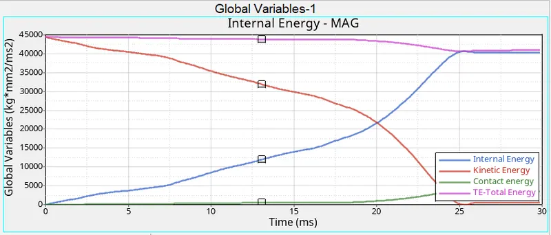
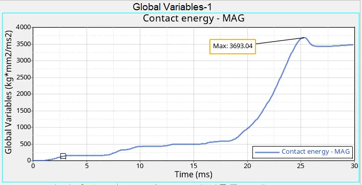
The contact energy has been created due to the contact between the elements will be start with the origine and after some time interval of 20ms gradually increases max. up to the 3693.04 as shown in below.
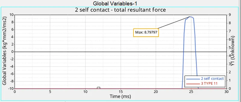
The below shown of self contact within the tube in the form of elements collide with each other. The self contact has been increase from the origine and gradually increases w.r.t time intervals and its incrases the gradually of 10 to 30 has been shows the max of the 8.79797 and gets sudden drop has been shown below.
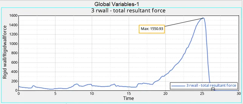
The regid wall force has been initially start with some instant and gradually increases with respect to time interval and reches max up to 1550.93. Its due to the resultant force has been more deformation of tube will be more as shown in below.
The given results got from the simulation.
Cycle time - 102300
Energy error - -7.5%
Mass error - 0%
Elapsed time = 383.08 s
case 4 Remove both notches and remove boundary condition on rigid body node then run.
Import the tube model in to the GUI.
By using the node edit>aline nodes > select nodes> aline.
first and second nodes select the other nodes to make aline.
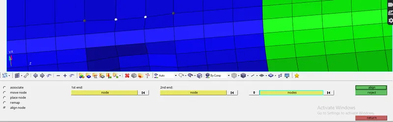
All notches can remove from the tube and make it aline the model as shown in above.
Also as per the condition the boundary conditions are remove as showing in below.
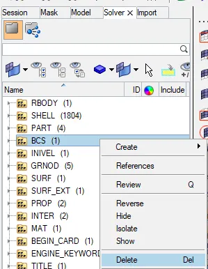
By creating the contact force to crating the INTER.
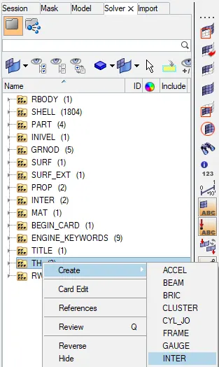
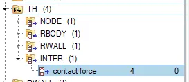
Select the contact force and crate /edit to select.
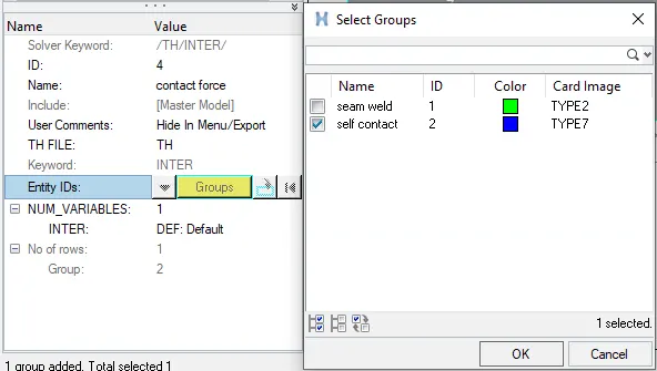
The groups select the self contact and select ok.
For the self contact assign the self contat parameters can be assign as shown in below.
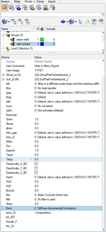
After assigning all parameters the tube will be seems to be as shown in below.
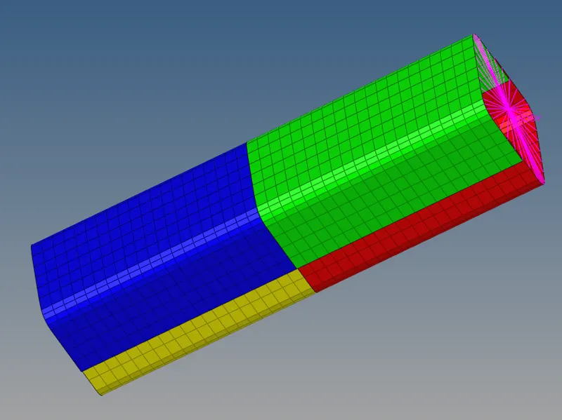
Now the tube is ready to make simulation as shown in below.
Slect the include connectors and -nt 4.

After finished simulation runs the 0001.out file will be seems to be as shown in below.
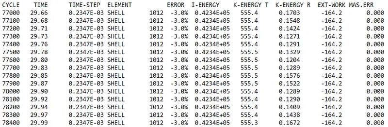
The simulation have the proper file of the out files and h3d files and T01 file has been created.

import the animation file of h3d file and select apply the shown the animation view of the tube.
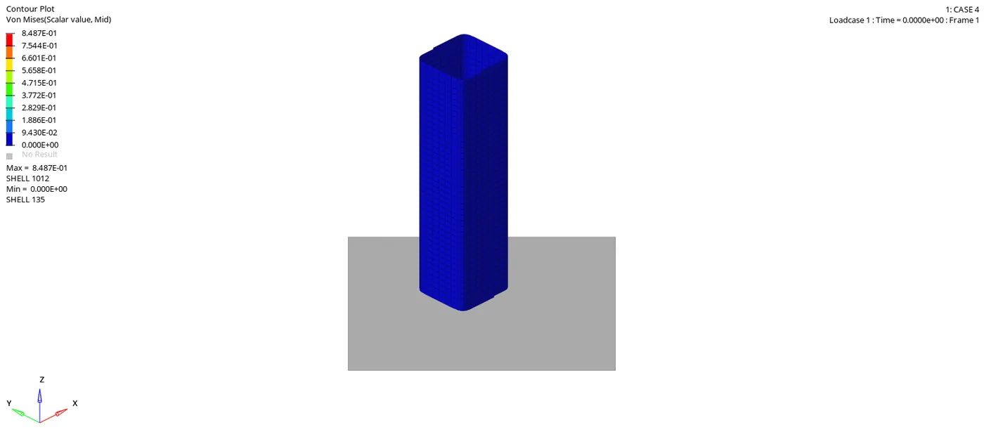
Similarly import the T01 file and apply.

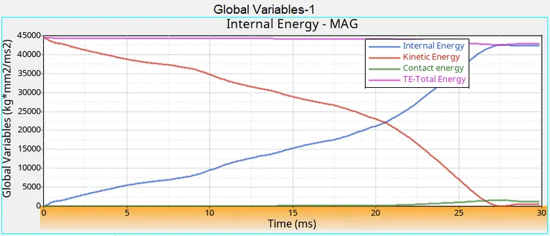
The global variables of the combination will be the as shown in below.
- The tube has initially have high kinetic energy and after some time interval the kinetic energy has been decreses as shown in below.
- As initially not have any deformation in the tube so initial energy has been starts from origine. After tube gets deformed with the increasing the graph .
- The total energy has beeen of the total resultant energy has been taking in to count.
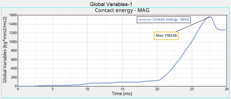
The contact energy has been created due to the contact between the elements will be start with the origine and after some time interval of 20ms gradually increases max. up to the 1563.06 as shown in below.
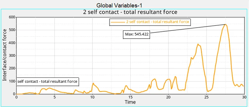
The below shown of self contact within the tube in the form of elements collide with each other. The self contact has been increase from the origine and gradually increases w.r.t time intervals and its incrases the gradually of 25 to 30 has been shows the max of the 645.422 and gets sudden drop has been shown below.
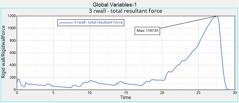
The regid wall force has been initially start with some instant and gradually increases with respect to time interval and reches max up to 1197.91. Its due to the resultant force has been more deformation of tube will be more as shown in below.
The given results got from the simulation.
Cycle time - 78400
Energy error - -3.0%
Mass error - 0%
Elapsed time = 141.70 s
Case 5 Create a new notch in the middle ,select the whole section and run.
Create the new inter for the contact forces as shown in below.
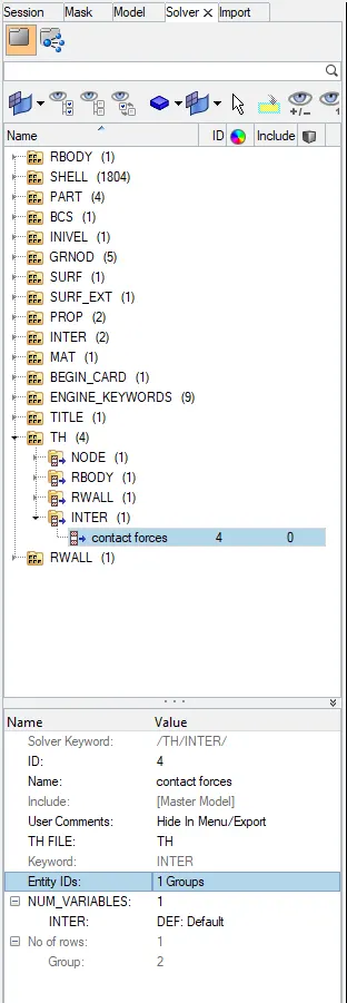
The below shown select the entity IDs select te group as the self contact as shown in below.
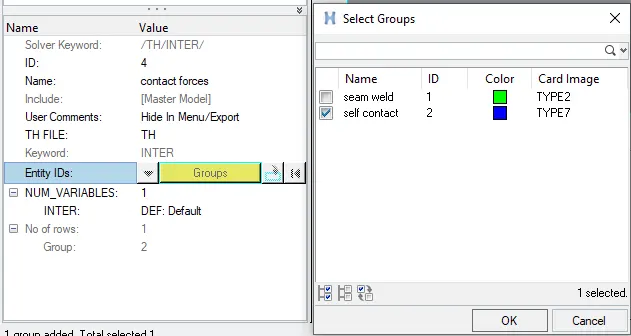
For the self contact assign the self contat parameters can be assign as shown in below.
Now the component is ready for the simulation with the assigning the all include the connections and to increase the speed of -nt 4.

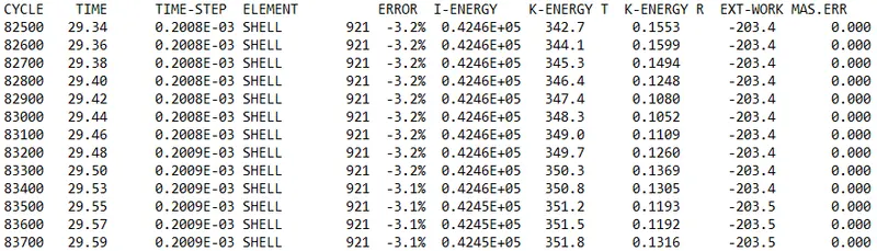
After run the simulation the file of 0001.out file will be like as shown in below.

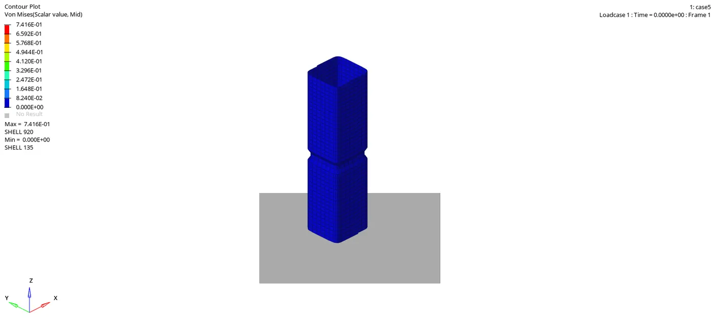
Import the h3d file and apply on the screen.

The below shown animation image should be seen in hyperview as shown in below.
Silmilarly for the open the graph , import the T01 file and apply in to the screen.

The global variables of the combination will be the as shown in below.
- The tube has initially have high kinetic energy and after some time interval the kinetic energy has been decreses. It is due to the initially have high K.E but as we gone for the some time interval the velocty decteses and the graph has been showing down as shown in below.
- As initially not have any deformation in the tube so initial energy has been starts from origine. After tube gets deformed with the increasing the graph .
- The total energy has beeen of the total resultant energy has been taking in to count.
The contact energy has been created due to the contact between the elements will be start with the origine and after some time interval of 20ms gradually increases max. up to the 1608.62 as shown in below.
The below shown of self contact within the tube in the form of elements collide with each other. The self contact has been increase from the origine and gradually increases w.r.t time intervals and its incrases the gradually of 25 to 30 has been shows the max of the 875.553 and gets sudden drop has been shown below.
The regid wall force has been initially start with some instant and gradually increases with respect to time interval and reches max up to 954.105. Its due to the resultant force has been more deformation of tube will be more as shown in below.
The given results got from the simulation.
Cycle time - 85700
Energy error - -3.1%
Mass error - 0%
Elapsed time = 170.99 s
Case 6 Create a new notch with nodes only from opposing 2 faces and run.
As per the conditions the nodes are to be select and as per the axis and using the translate option make the notches for 2 opposite faces.

After creating the notches as shown in below figure.
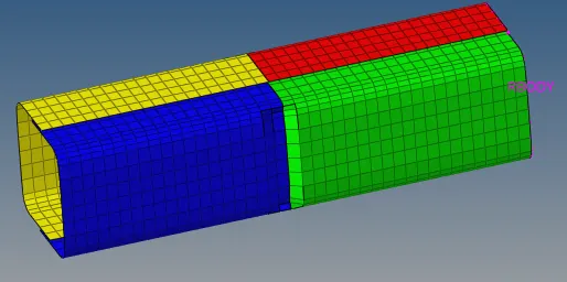
Now the component is ready for the simulation with the assigning the all include the connections and to increase the speed of -nt 4.
After run the simulation the file of 0001.out file will be like as shown in below.
Import the h3d file and apply on the screen.
The below shown animation image should be seen in hyperview as shown in below.
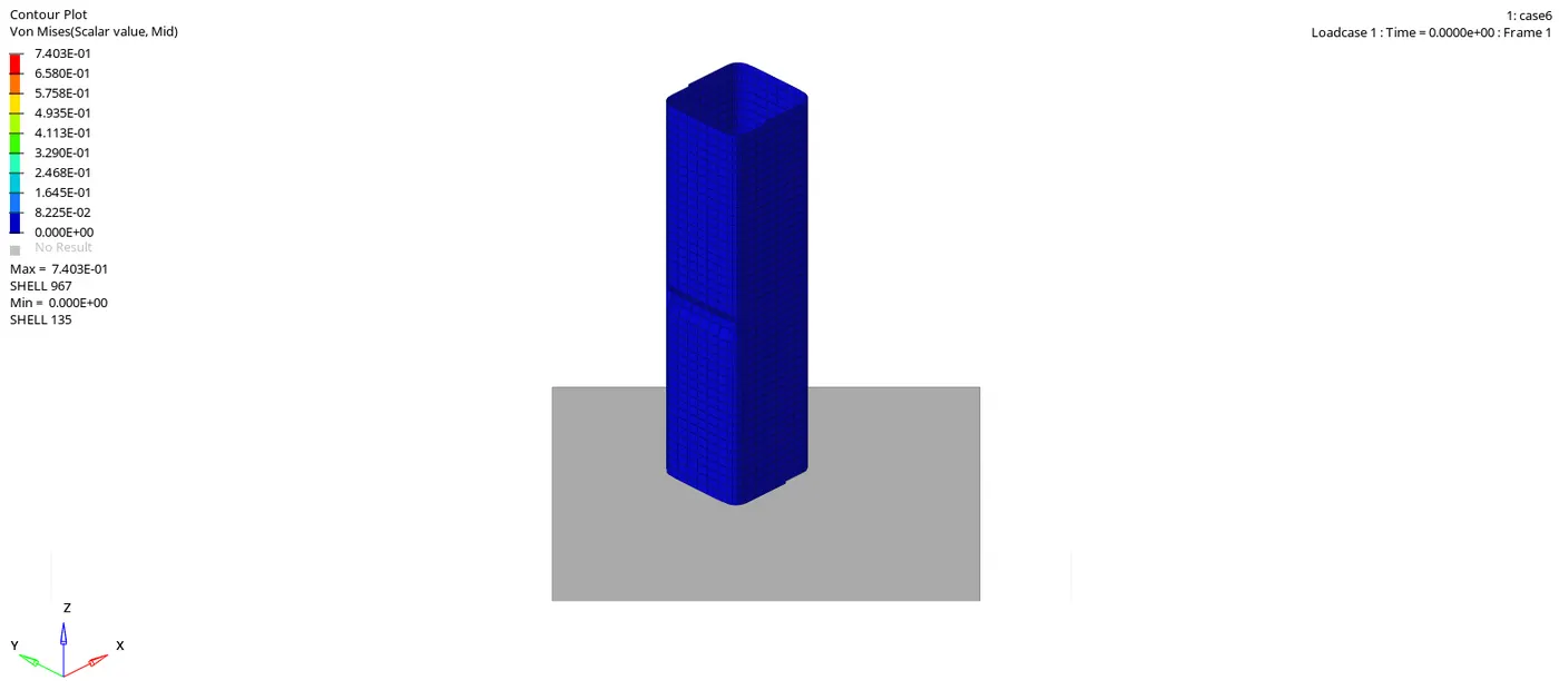
Silmilarly for the open the graph , import the T01 file and apply in to the screen.
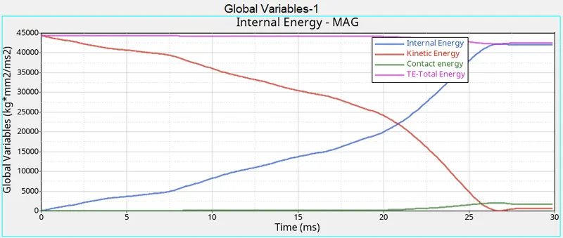
The global variables of the combination will be the as shown in below.
- The tube has initially have high kinetic energy and after some time interval the kinetic energy has been decreses. It is due to the initially have high K.E but as we gone for the some time interval the velocty decteses and the graph has been showing down as shown in below.
- As initially not have any deformation in the tube so initial energy has been starts from origine. After tube gets deformed with the increasing the graph .
- The total energy has beeen of the total resultant energy has been taking in to count.
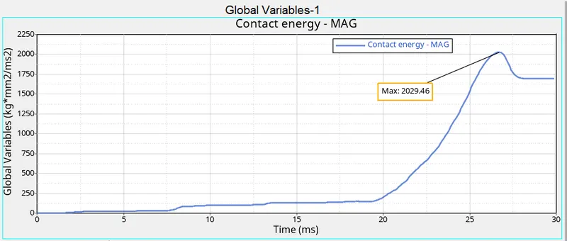
The contact energy has been created due to the contact between the elements will be start with the origine and after some time interval of 20ms gradually increases max. up to the 2029.46 as shown in below.
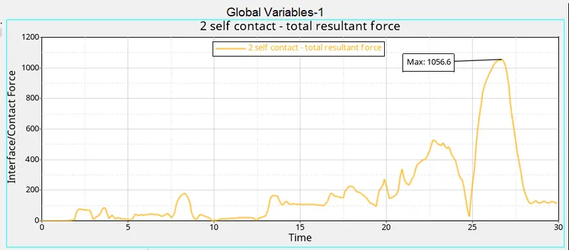
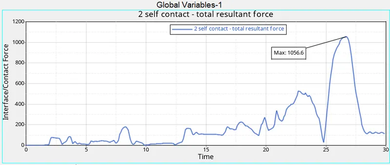
The below shown of self contact within the tube in the form of elements collide with each other. The self contact has been increase from the origine and gradually increases w.r.t time intervals and its incrases the gradually of 25 to 30 has been shows the max of the 1056.6 and gets sudden drop has been shown below.
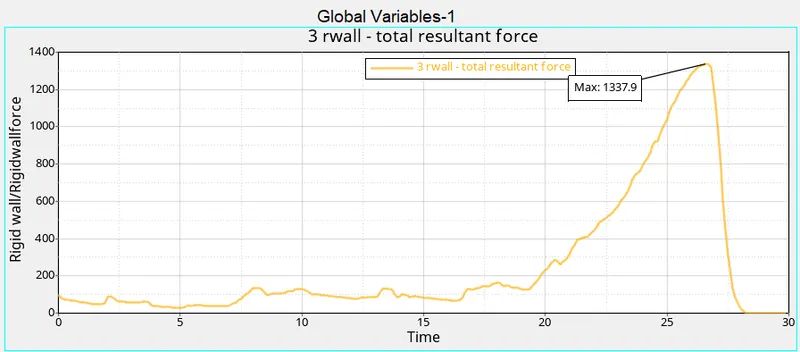
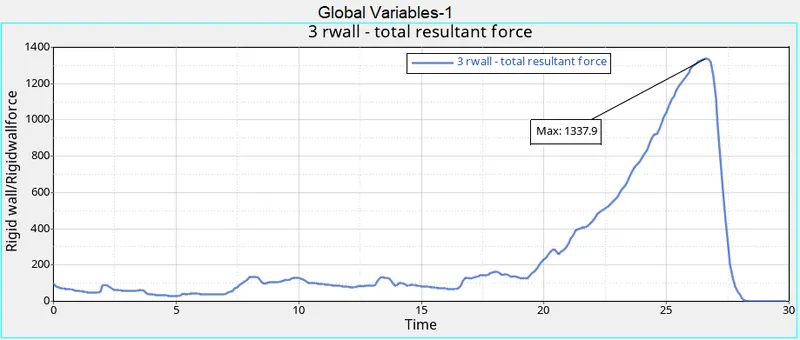
The regid wall force has been initially start with some instant and gradually increases with respect to time interval and reches max up to 1337.9. Its due to the resultant force has been more deformation of tube will be more as shown in below.
The given results got from the simulation.
Cycle time - 90700
Energy error - -3.2%
Mass error - 0%
Elapsed time = 168.47 s
Results
For doing these different cases there is the resuls for comparisons as shown in below table.
| KINETIC ENERGY | ENERGY ERROR | MASS ERROR | CYCLE TIME | ELAPSED TIME | CONTACT ENERGY | CONTACT FORCE | REGID WALL FORCE | |
| Case 1 | 592.6 | -3.8% | 0.000 | 150.28 s | 83400 | 2029.46 | 1056.6 | 1337.9 |
| Case 2 | 592.6 | -3.8% | 0.000 | 152.13 s | 83400 | 2029.46 | 1056.6 | 1337.9 |
| Case 3 | 572.0 | -7.5% | 0.000 | 383.08 s | 102300 | 3639.04 | 8.7979 | 1550.93 |
| Case 4 | 555.3 | -3.0% | 0.000 | 141.70 s | 78400 | 1563.06 | 545.422 | 1197.91 |
| Case 5 | 353.0 | -3.1% | 0.000 | 170.99 s | 85700 | 1608.62 | 875.553 | 954.105 |
| Case 6 | 613.3 | -3.2% | 0.000 | 168.47 s | 90700 | 2029.46 | 1056.6 | 1337.9 |
By doing these six cases for to identify the how contact energy and contact force will be effected with six different cases are discussed below.
For case 1 and case 2 has been similar results but the assigning the Inacti =6 for the case 2 has been not gives not have that much of change over during the simulation. Only change will be happen in case of the cycle time rest of all other cases will be same.
For case 3 Interface Type 11: Edge to Edge Contact due to this the contact energy, contact force, regid wall force, elapsed time and energy error also more as compered to the all cases.
For case 4 is of removing the all notches and boundary conditions the simulation will gives the results of the low contact energy and contact force has been low and cycle time will be low respectively.
For the case 5 creating the new notches of the component will be create the increasing the contact energy and contact force with the cycle time will takes more.
For the case 6 creating the new notches of the opposite 2 faces and run the simulation. The kinetic energy has been more and contact energy and contact force will be more and its due to the colliding the elements with each other.
Conclusion
By doing this challenge interface and notches has been of contact energy and contact force is gives the tube has been varies with have different cases has been concluded with the compering the results.