Week 3 - 2D meshing for sheet metal
Aim- To determine the given Hood model, Take the mid surface for all the components after checking the geometrical errors and mesh the mid surface with the given element Quality criteria.
Procedure - open the ANSA softwere with proper way and while opening mension the command arguments, type the "-performance_mode 3".Press ok.
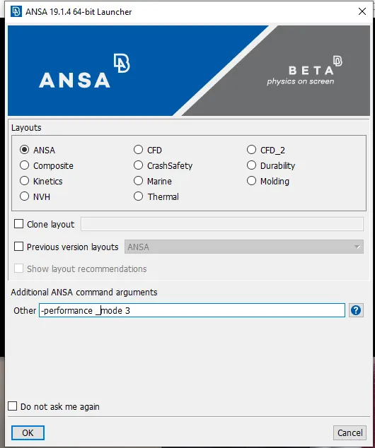
The softwere is open and select the downloaded file from folder and fit in to screen.
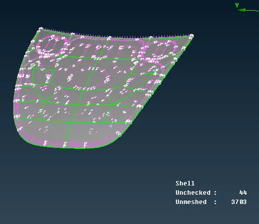
The component is have the 4 different type of component to it. Create different folders and make it seperate.
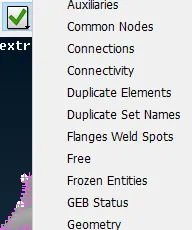
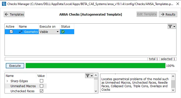
Make the geometrical cleanup for the component, by selecting the check manager.
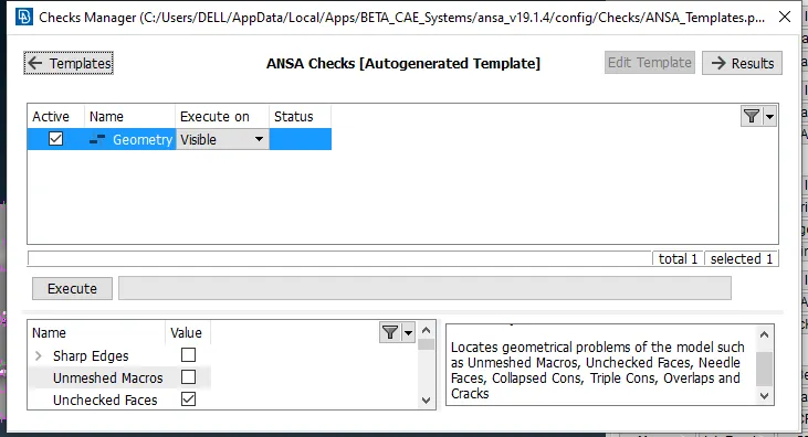
Execute the geometrical error as shown in below.
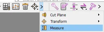
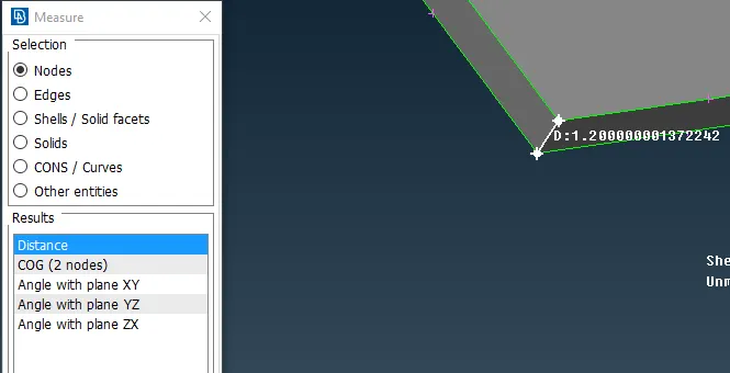
Measure the thickness of the component and by selecting the nodes
As shown below, thickness of the component has been checked.
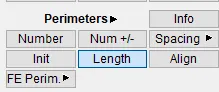
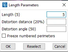
Put the length for the parameter and macros by selecting the length.
select the parameter and set the value.
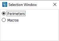
Also for the macros, set the lenth for that.
After the component is seems like below shown.
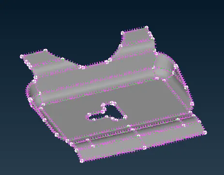
Make the component as the Topo by selecting the component and click on middle mouse botton
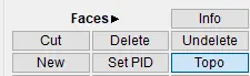
The component is becomes shown in below .
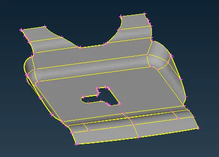
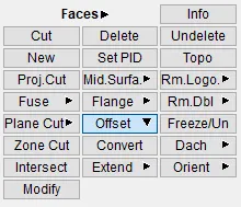
To extract mid surface of this component
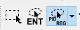
Select the PID REG and select any of the surface of component.
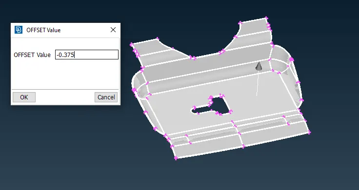
Press the middle botton click and assign the offset value as per the shown vector.
If you want original face, select yes or no.
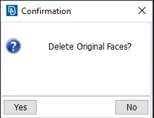
If YES, extrcting the midsurface id with perent component as shown in below.
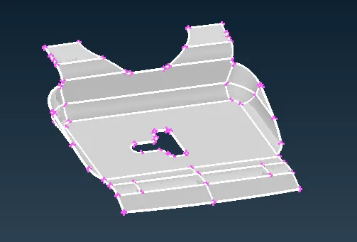
Create seperate PID for the mid surface by selecting the i- option and selecting the PID region for the below component.
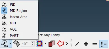
The final component has been shown in below.
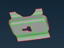
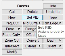
Set PID for above mid surface for the component
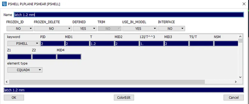
The thickness has beeen mention for the same.
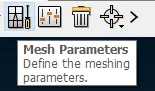
After set the mesh parameter by selecting the command.
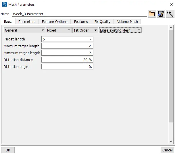
The mesh parameter is as shown in below
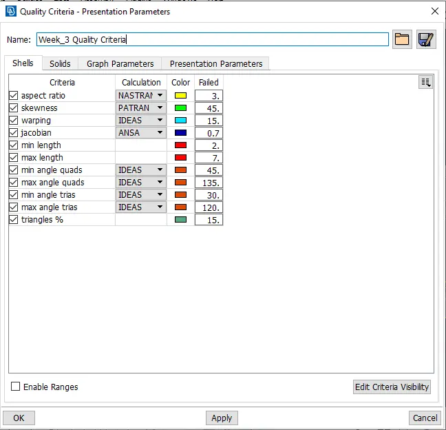
Also set for the quality criteria parameters for the component by selecting the quality parameter.
All quality parameters can be set as shown in below.
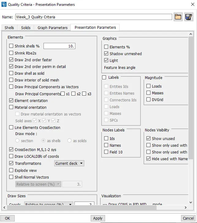
In quality criteria parameter keep presentation parameter setting, by selecting the element% and demand effect.
These above shown mesh parameters and quality creteria parameters can be fix for the all 4 component by selecting the settings.
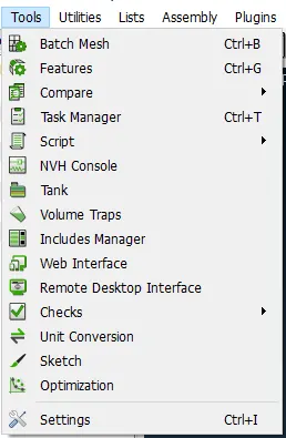
In settings, save all the settings for all component and select apply.
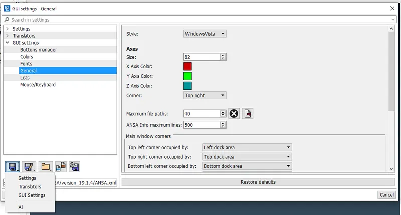
Do this procedure before meshing start.
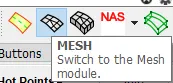
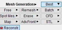
To select the Mesh generation, select the best to do meshing.
select the area and do the best mesh. It was creating the so many trias and and use.
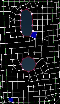
Do the reconstruction option and select the area.
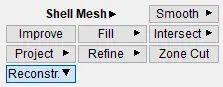
Do the proper mesh flow and as shown in below.
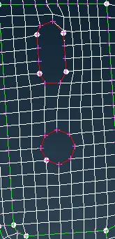
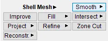
Any distortion in elements use the smooth and make it properly.
Max. remove the max tria elements and for all component.
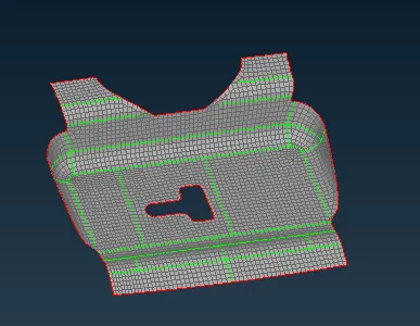
Keep active mode for hidden and wire frame mode.

Mesh has been done the as per the given criteria. If facing any problem with unmeshed or any kind of off can be rectify by selecting by perticular selection.
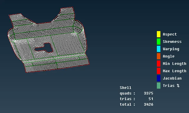
Similarly for the hinge also have the same procedure to do with above shown.

Extracting the midsurface from the offset command and shown in below.
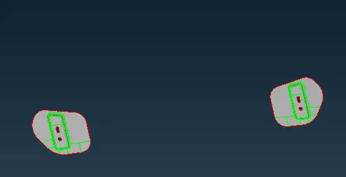
Before going to mesh the component the inside free edges can be check properly. It should be even number.
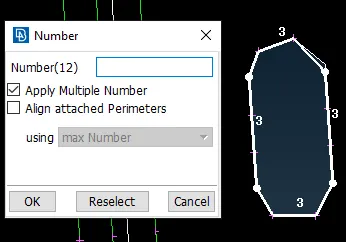
Do the meshing properly as per the given criteria. The final mesh is to be shown as shown below.
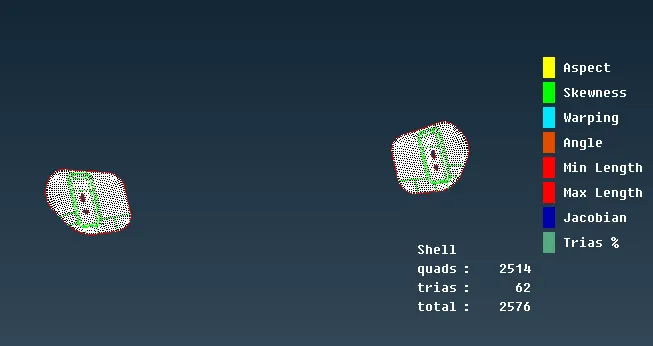
After eliminate all the errors for the hinge component.

Select the outer perent component by selecting the glow option.
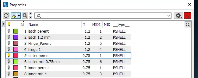
The component has been shown as shown below.
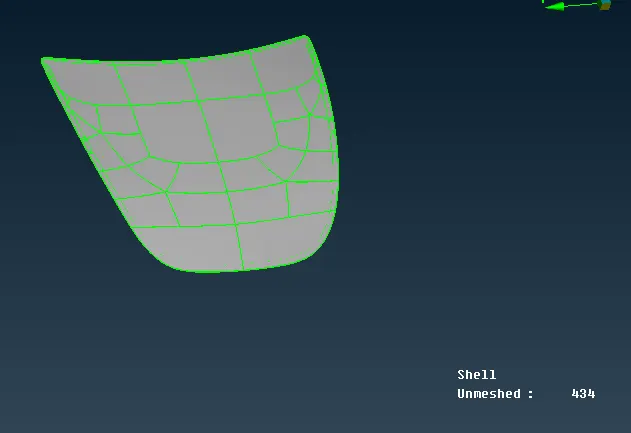
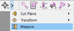
Mesure the thickness of the component.
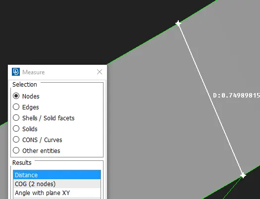
By selecting the 2 nodes and its shows the distance.
Similarly for the hood outer component has been extracted the mid surface.
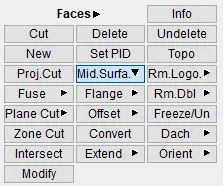
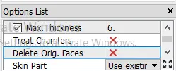
Select the option list and select cancel the delete the original faces.
Select the PID REG and select any of the surface of component.
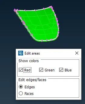
Select the component and the edit areas and the face can be shown by colour change. Click the middle botton of mouse.
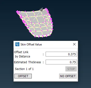
If YES, extrcting the midsurface id with perent component as shown in below.
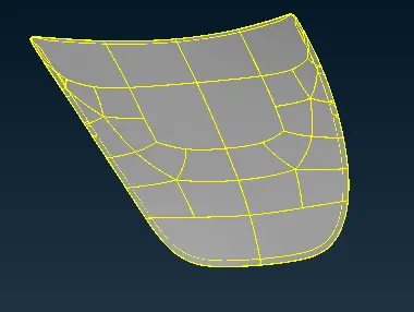
Create seperate PID for the mid surface by selecting the i- option and selecting the PID region for the below component.
The final component has been shown in below.
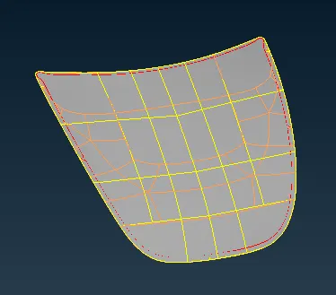
Set PID for above mid surface for the component
The thickness has beeen mention for the same.
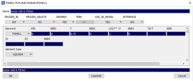
Do this procedure before meshing start.
To select the Mesh generation, select the best to do meshing.
The max. cuts can be done as shown in below.
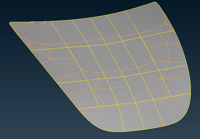
In macros and slect the cut option.
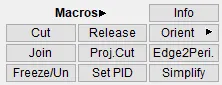
Use the cut option and delete the unnecessary lines. Make the need full cuts and split properly using the cut.
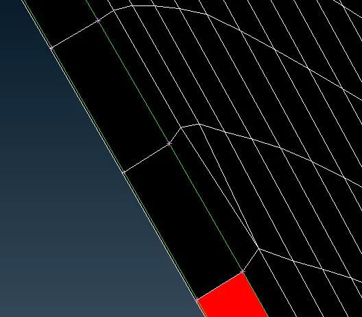
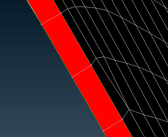
In hemming region some of elements can be failed for min. length as shown in above.
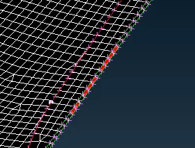
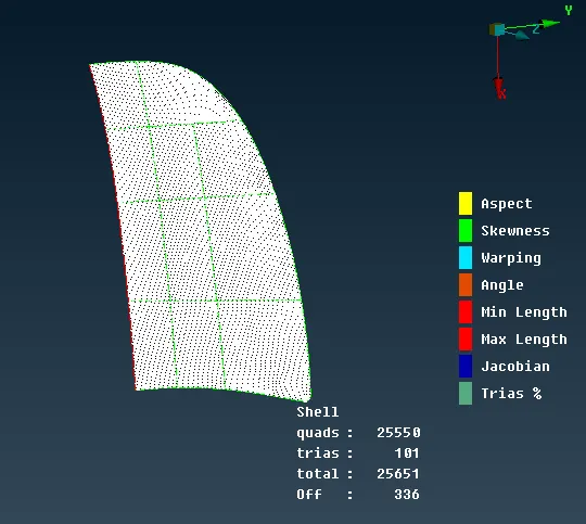
The component is symmetric component and its needs to be make the proper symmetric over the opposite.
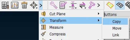
Select the transform and select the copy.
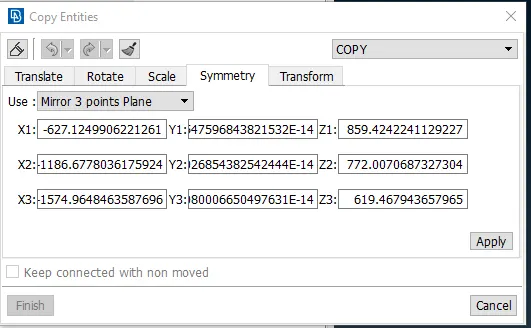
The copies the entity by selection the elements with surface, selecting the mirror by 3 points plane.
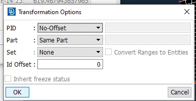
Press middle click botton for mouse and press ok.
The component is of gets symmetrical and its shown in below.
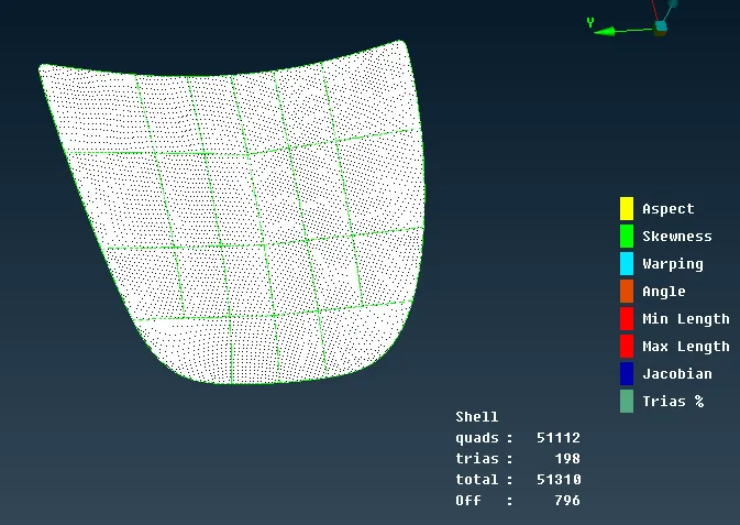
Similarly do the same procedure for the below shown component.
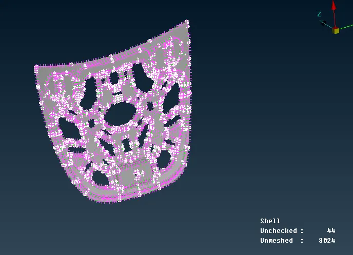
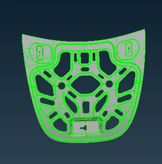
Creating the mid surface for the same component of 0.75 mm thickness.
If doing the meshing feature capuring can be achived by using the origine option.
By using origine option the below shown the changes.
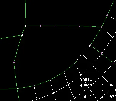
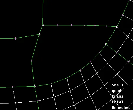
The finally made the symmetrical about the inner component below shown.
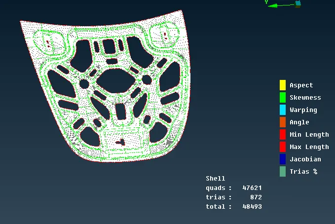
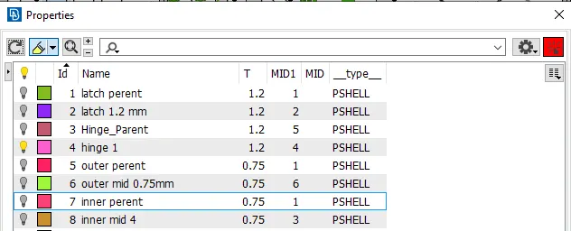
All creating the components can be create the seperate collector for perent and mid surfaces as shown in below.
Conclusion
For doing this component meshing to know various type of tools to extract mid surface and meshing tools.