Week 8 - Universal Joint
Aim- To perform a transient analysis on a Universal Joint using the transient structural analysis.
Objective
Transient structural analysis on a double universal joint with a spring using three different materials: Structural Steel, Stainless Steel, and Titanium alloy
To obtain the Equivalent stress and total deformation for all three cases and compare them.
Use a refined mesh if possible for the academic license.
Plot the Equivalent Stress, Total Deformation, and Equivalent Elastic Strain and compare them for all three cases.
Introduction
The term universal joint was used in the 18th century and was in common use in the 19th century. Edmund Morewood's 1844 patent for a metal coating machine called for a universal joint, by that name, to accommodate small alignment errors between the engine and rolling mill shafts.
A universal joint is a type of mechanical instrument used in many applications to transmit rotation through slightly misaligned shafts (See Figure 1). The misalignment correction is limited by the design of the shaft but can be amplified by the use of multiple universal joints
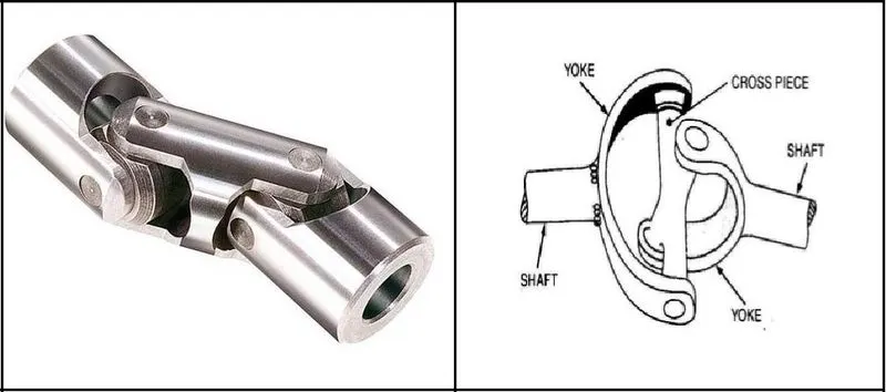
There are two types of universal joints, defined by their number of bending joints
A single joint: has only one bending aspect and is capable of operating at up to a 45-degree angle.
Double joint: utilizes two bending joints, the double u-joint can operate at angles up to 90 degrees.
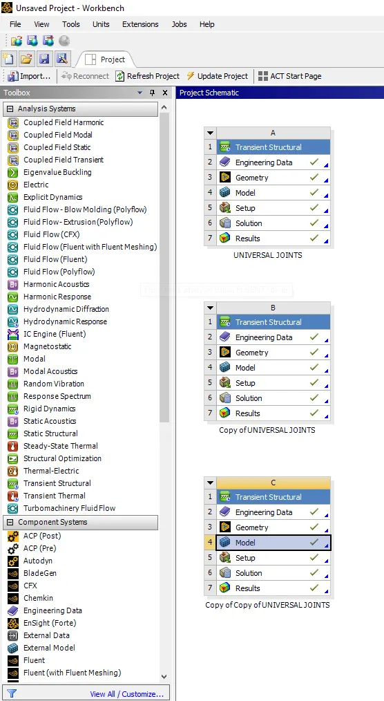
Procedure- To start the simulation by opening with the Ansys workbench.
Select the transient structure from the toolbox as shown below shown.
Procedure- To start the simulation by opening with the Ansys workbench.
Select the transient structure from the toolbox as shown below shown.
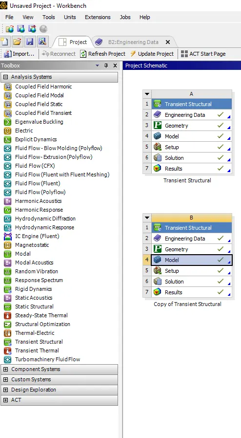
In transient structural selection to assign the material property in engineering data.
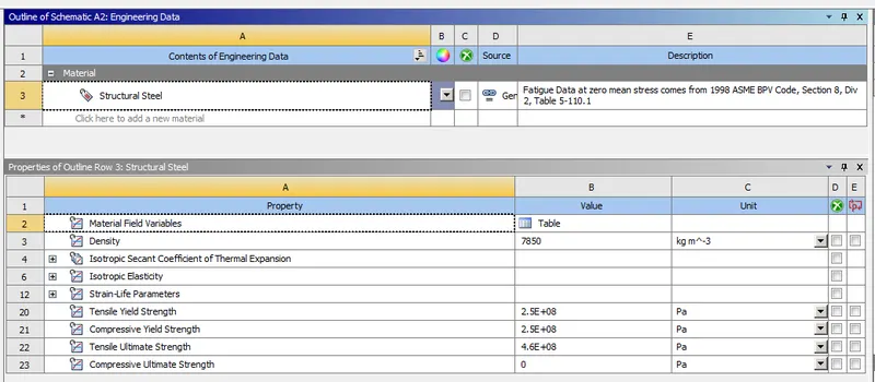
Update the engineering data as shown below.
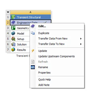
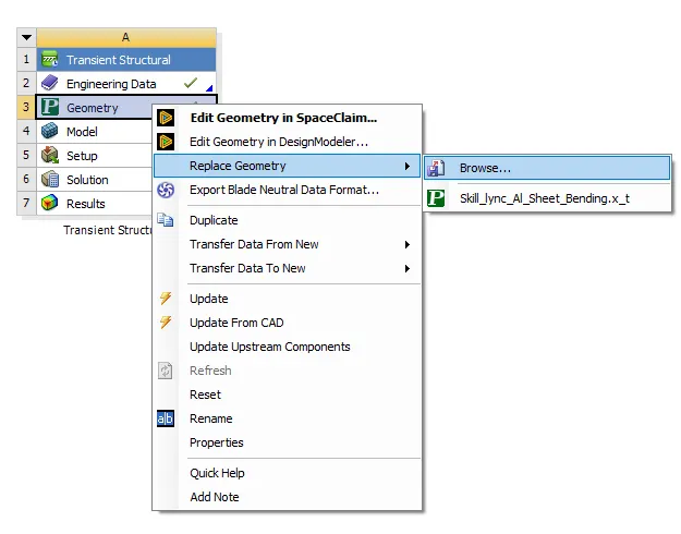
Also import the geometry from the browse with the updated geometry.
Import the geometry for the given model is of geometry and naming the component properly Select the material as the structural steel.
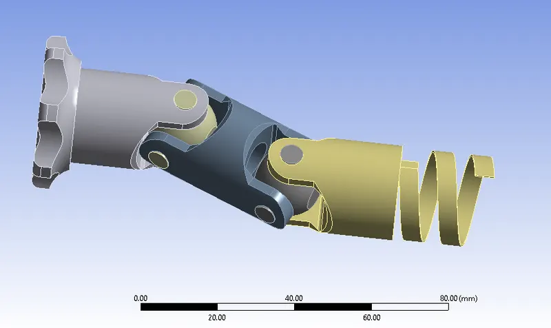
While opening the model is looks like on shown the screen as shown below.
For spring use the material as the structural steel for the given component.
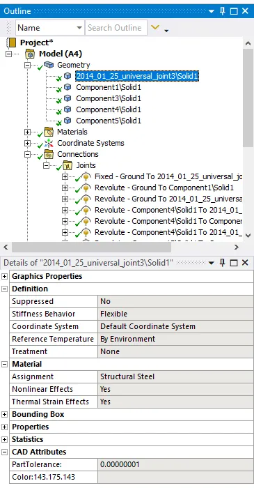
For other components are to be selected material as the structural steel.
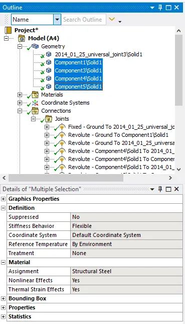
Do the fixed joints for the spring element as shown in below.
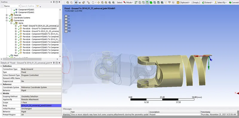
Create the revolute joints as shown below.
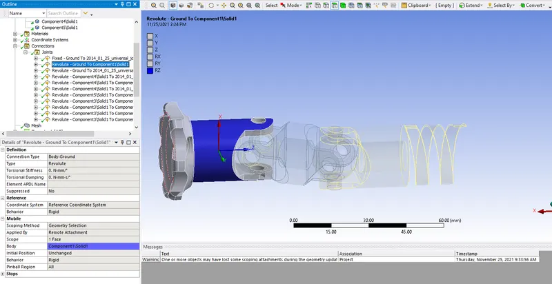
Create the revolute joints for all joints as shown below.
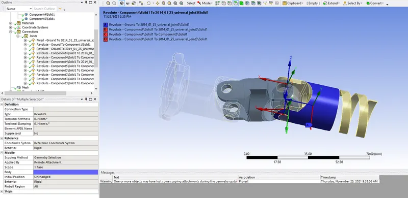
For another end also make the joints for all 4 joints as shown below.
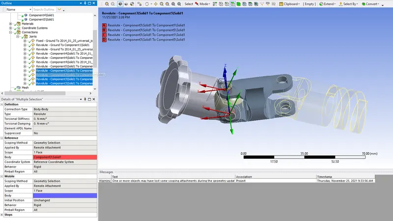
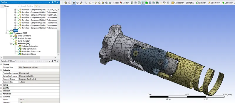
Generate the mesh with the size of the element of 5mm as shown below.
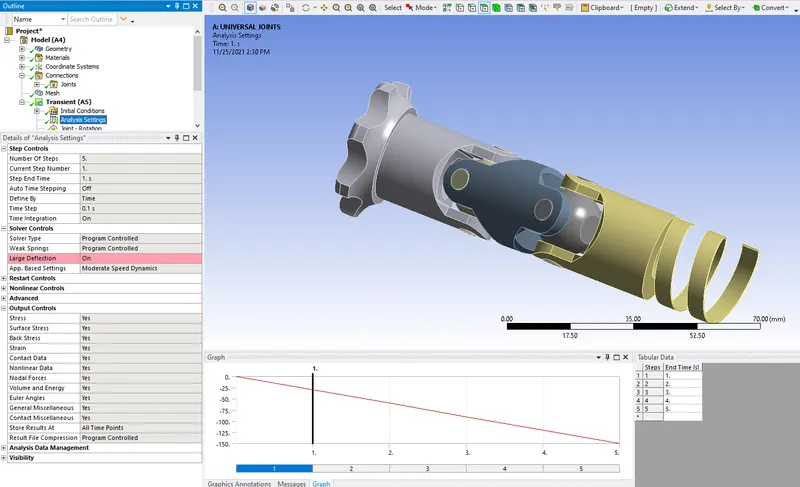
Do the analysis settings and large deflection was on as shown in below.
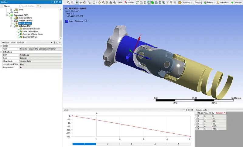
Create the joint for the rotation and select the component as shown below.
After solving the simulation the results can be plotted as shown below.
CASE 1
The total deformation for the component will be max. 38.637mm as shown below.
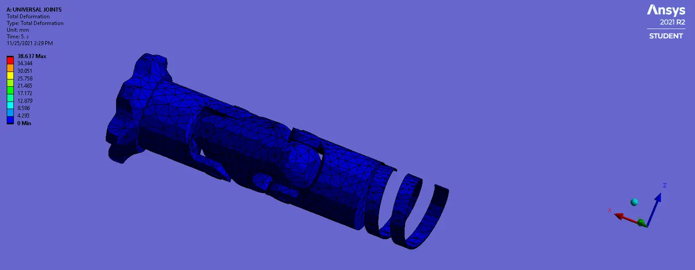
The elastic strain of the component will be max. will be 0.0084448 mm and min. will be the 2.7829e-14 as shown below.
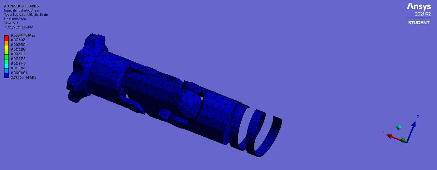
The equivalent stress for the given component is max. 1643MPa and min. 5.2415e-9MPa as shown below.
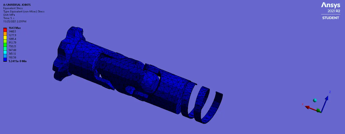
CASE 2
Strainless steel is used for the given component as shown below.
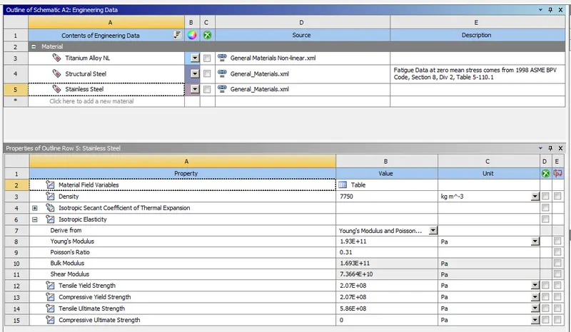
The universal joints are of stainless steel and for others used as structural steel as the same.
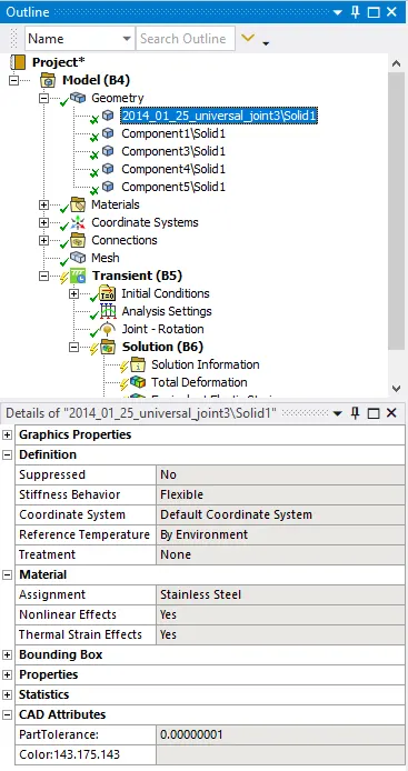
All settings are the same for this case. Run the simulation plot the all results as required.
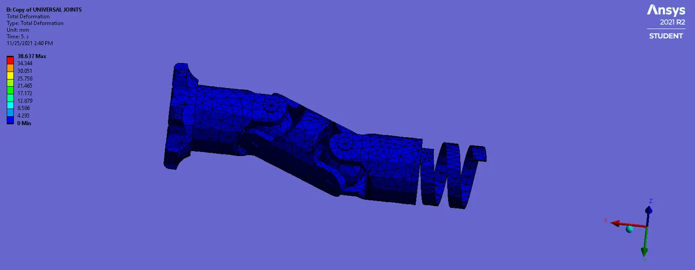
The total deformation for the component will be max. 38.637mm as shown below.
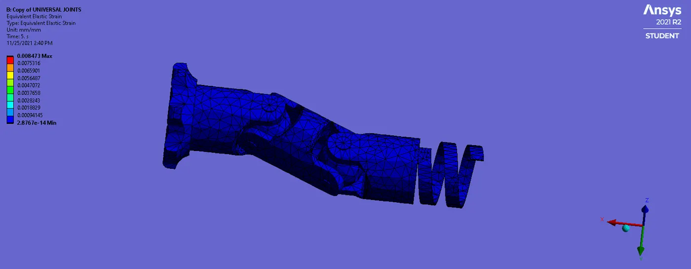
The elastic strain of the component will be max. will be 0.008473mm and min. will be the 2.8767e-14 as shown below.
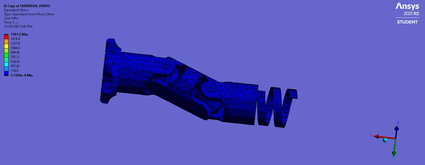
The equivalent stress is the max. 1591.2MPa and min. 5.3106e-9MPa as shown below.
CASE 3
Titanium alloy NL is used for the given component as shown below.
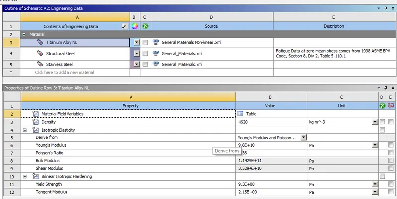
The universal joints are of Titanium alloy NL and for others used as structural steel as the same.
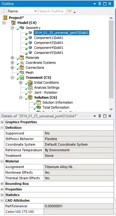
All settings are the same for this case. Run the simulation plot the all results as required.
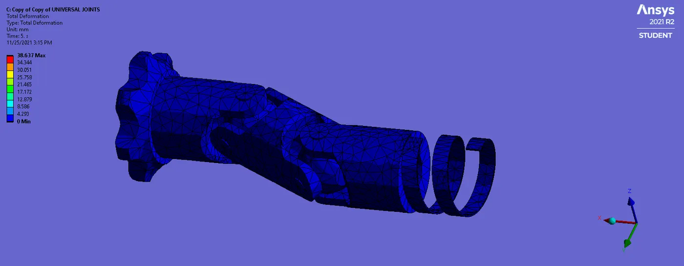
The total deformation for the component will be max. 38.637mm as shown below.
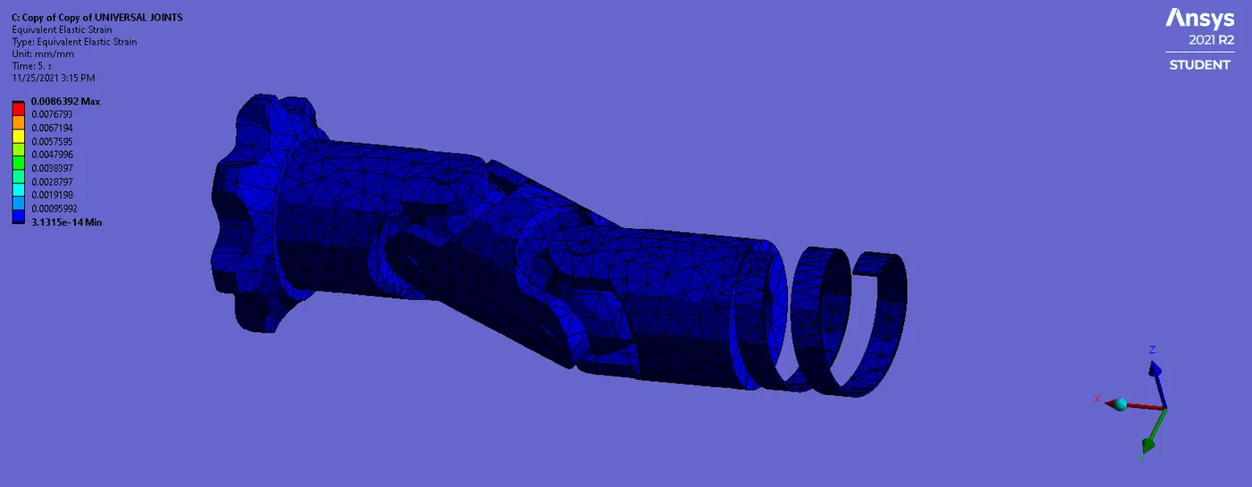
The elastic strain of the component will be max. will be 0.0086392mm and min. will be the 3.1315e-14 as shown below.
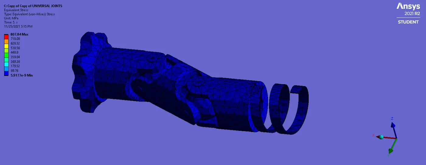
The equivalent stress is the max. 807.84MPa and min. 5.9177e-9MPa as shown below.
Results
All results are tabulated as per the cases as shown below.
| Total Deformation | Elastic strain | Equivalent stress | |
| Case 1 | 38.637mm | 0.0084448 mm | 1643MPa |
| Case 2 | 38.637mm | 0.008473mm | 1591.2MPa |
| Case 3 | 38.637mm | 0.0086392mm | 807.84MPa |
Conclusion
The total Deformation of the simulation will be of same for all the cases as 36.637mm shown in the table.
The elastic strain will be of min. 0.0084448mm and a max of 0.0086392 as shown in the above table its due to changing the property of materials.
The equivalent stress for the component has been max. for case 1, 1643MPa, and min of the 807.84MPa for case 3. It's due to the material property changes the stress will be changing.
https://drive.google.com/file/d/19pN97OKOGvwx_YsUIO-1UieC3S4p0SiU/view?usp=sharing