Assignment 6-Frontal Crash Simulation Challenge
Aim - To perform the frantal crash analyasis for the given BIW model.
Objectives - The following perform the frantal crash analysis has done below shown.
1) Import the BIW model in to GUI.
2) First do the mass balancing in the hypercrash and export the file.
3) Import the file of the 0000.rad in to the hypermesh.
4) Check the unit system, create interface, penitration check,Regid wall , unused, empty.
5) Assign the parameters values to create interface of standerd parameters for crash.
6) Assign the parameters for the initial velocity, time step,run time, accelerometer,Intrusion, section,TH.
7) Simulate the component and get the results and make conclusions.
Introduction
Crashworthiness is the ability of a structure to protect its occupants during an impact. This is commonly tested when investigating the safety of and vehicle. Depending on the nature of the impact and the vehicle involved, different criteria are used to determine the crashworthiness of the structure. Crashworthiness may be assessed either prospectively, using computer models (e.g.,LS- DYNA, PAM-CRASH etc) or experiments, or retrospectively by analyzing crash outcomes. Several criteria are used to assess crashworthiness prospectively, including the deformation patterns of the vehicle structure, the acceleration experienced by the vehicle during an impact, and the probability of injury predicted by human body models. Injury probability is defined using criteria, which are mechanical parameters (e.g., force, acceleration, or deformation) that correlate with injury risk. A common injury criterion is the Head impact criterion (HIC). Crashworthiness is assessed retrospectively by analyzing injury risk in real-world crashes, often using regression or other statistical techniques to control for the myriad of confounders that are present in crashes.
The frantal crash test there is the frantal impact load distribution in to BIW as shown in the below shown in figure. The variation load steps in the initially and how it will distributed depends on the BIW structure.
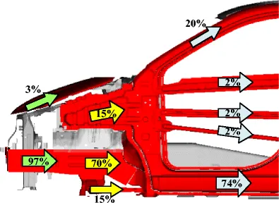
While crash has been done every automotive company with respect to there standerd and parameters for crash. The crash test has been gives the accurate results for seafty and injuries happen to the dummy body. Against these results need to improve the seafty features and the inside peson in the car shuld safe. Below image shows the, when frant crash will happen the affects the car and with dummy model have the injuries will analyse as shown in below.
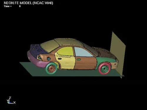
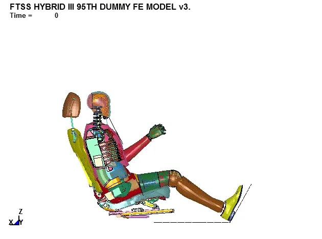
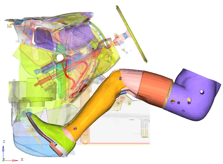
NCAP crashes or other crash standerd frantal crash of cars at 35 mph (56 kph) in both frontal and side impact, and rates the cars based on how likely the occupants are to be injured during a crash. Researchers have used crash test data to determine the reality of injuries that may be sustained in a crash.
Procedure
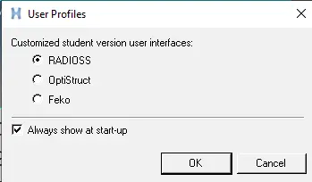
Open the hypermesh and select the profile as radioss.
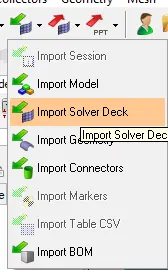
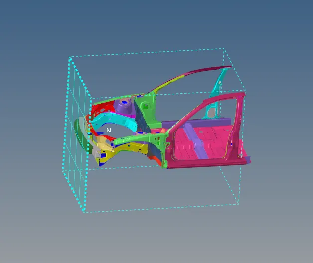
Import the starter file from the solver deck as shown in below and import in to GUI.
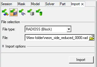
From the solver deck import the model of 0000.rad.
The process flow should be start from the mass balancing.
Check the mass details of the mass ,Cog and inertia has been shown below.
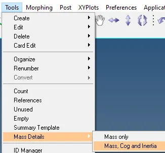
Mass balancing
A mass balance, also called a material balance, is an application of conversion of mass to the analysis of physical systems. By accounting for material entering and leaving a system, mass flows can be identified which might have been unknown, or difficult to measure without this technique.
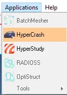
For the mass balancing will done by using the hypercrash.
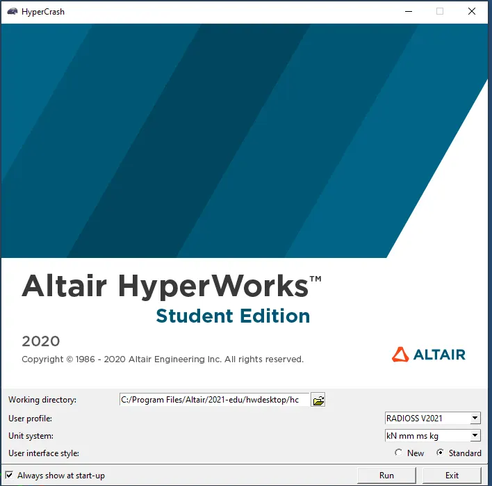
After selecting the proper unit system and run the model.
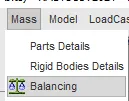
When it was open the by using the mass balancing as shown in below.
Select the COG point and it will show the COG point.
The current mass is to be 166kg so as per the given statement make it 700kg.
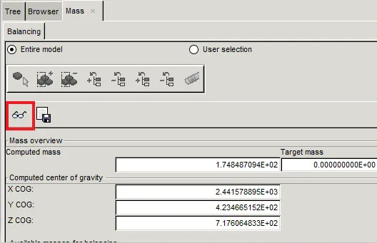
This was showing the 166 so need to make balacne up to the 700 kg.
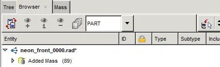
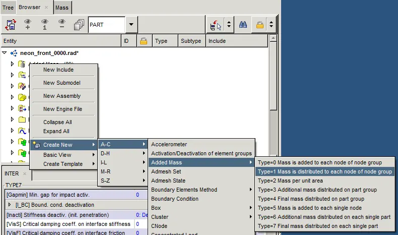
Select it for the added mass by selecting the create new A-C of added mass and select the added mass select the type=1(mass is distributed to each node group).
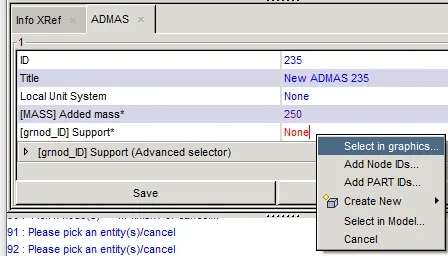
Select with the right click and select the graphics.
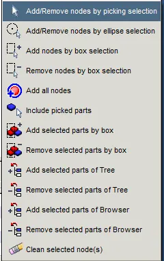
By selecting the add/remove the nodes by picking selection its ready to add the mass.
The added the all masses in to the floor pannel. The select by nodes and maid the balancing up to required weight.
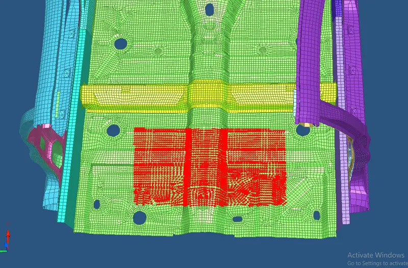
After selecting the all nodes for the ENTER botton and select as the save as shown in the below.
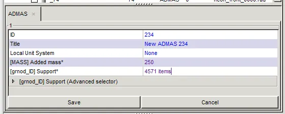
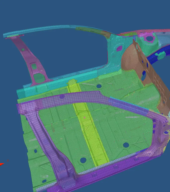
Similarly continueing with the added mass has been generated so, needs to make the bancing with the added masses up to 700kg.
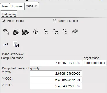
The above shown the COG of the points has been becomes the 700kg as shown in below.
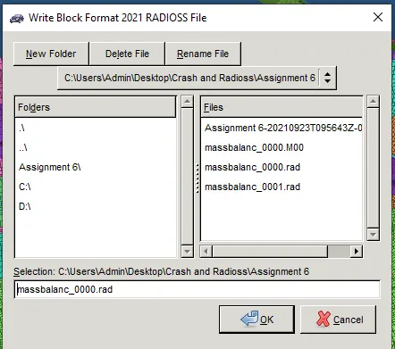
Export the radioss file after the finished the mass balancing as shown in below.
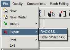
Select the location to be save into the proper file selection.
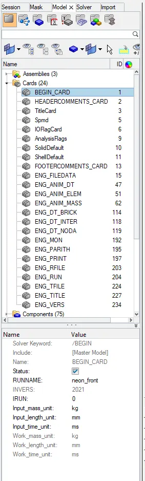
After importing that file in to solver deck needs to check the step by step procedure to proceed further.
The starts with the Begin card to confirm the units of the given component. The below shown the mass, length and time for the component.
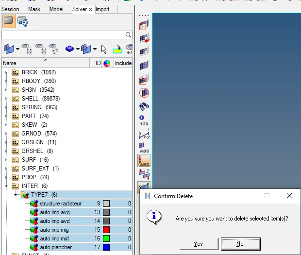
By create the type 7 card for the given component and select the unnecessary items and delete it.
Below shown the creating the TYPE7 contact with the selected the crash test standerd parameters can be selected for the given the model.
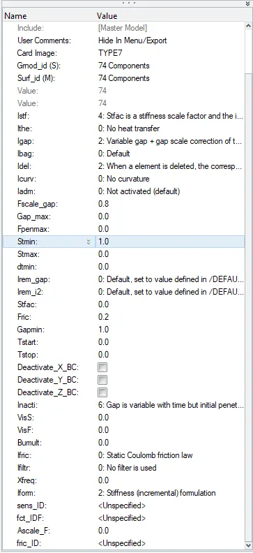
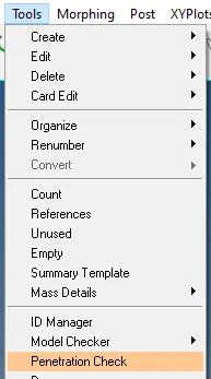
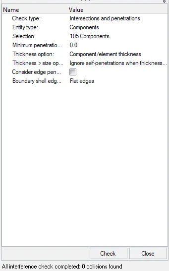
After assigning the all type-7 parameters in to the model do the penitration check for the all component and the interface check has been completed as shown in the figure.
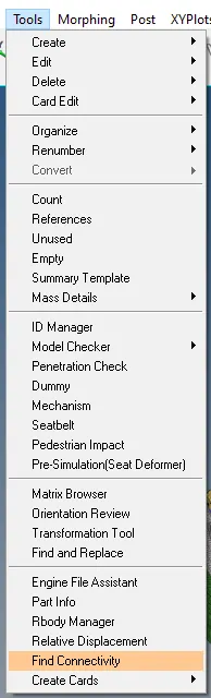
Check for the connectivity in the components by selecting the tools select the find connectivity
The create the rwall/ regid wall has been pop up with below shown window.

In that select the rigid wall and name it. Its pop up with the to assign the engineering data.
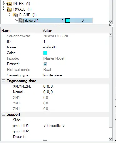
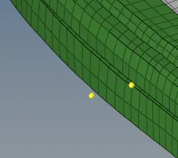
Select the temp node on the bumper and translate in to the x-axis with of distance 30
In the engineering data select the position with the selecting node.
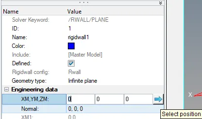
After the selecting the node, select it is to proceed.

After selecting the node the engineering data will be update the, at what distane node is there. Select the -1 normal to the x-axis and keep other axis should be 0 as shown in below. Also give the Dsearch shoud be specify in the search distance.
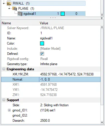
The creating the regid body for the frantal crash will be shown as shown in below.
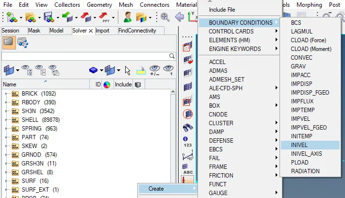
Create the boundary conditions of selecting the INVEL in to the solver.
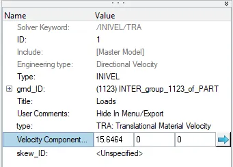
The solver is of the velocity of the component will give as per the FMVSS standerds of the material will be of the 15.646ms .
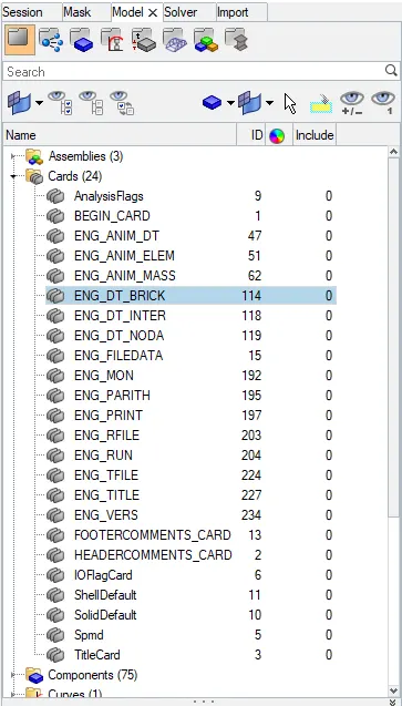
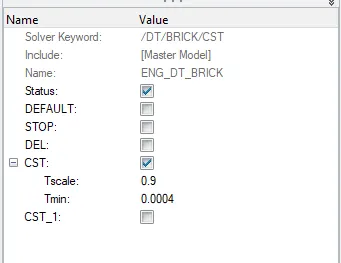
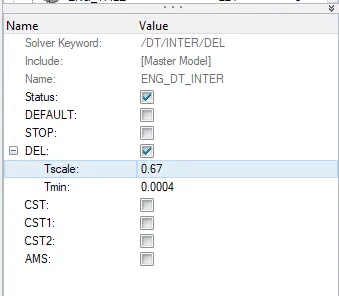
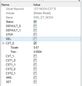
The cards to be assign in to the model of BRIC,INTER and NODA as shown in below.
Assign the Tscale and Tmin of the values of the 0.9 and 0.0004 respectively as shown in below.
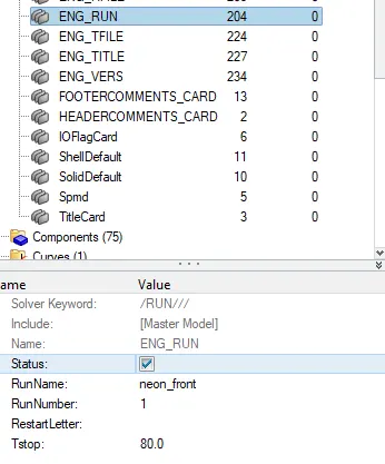
Assign the Tstop value of the 80 has to be in the ENG_RUN card as per the given in the statement.
Acclerometer - The accelerometer will assign to know the how much of acceleration will happen in the particular node we can analyse the condition.
Create the acclerometer for the given component in such a way that the by using the display numers to use and create the specific node of the model with exact opposite node will be select the introduce the node.
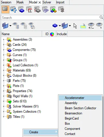
Select with the node ID and select the node and crate for the accelerometer.
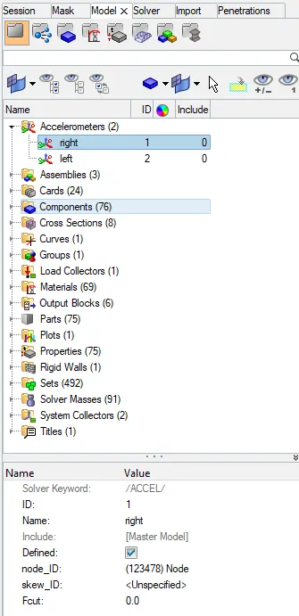
The accelerometer has been shown in below.
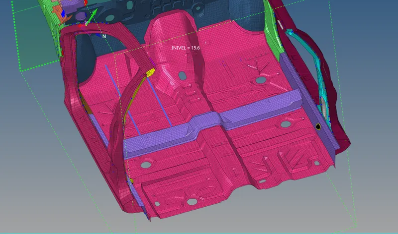
Intrusions -The intrusions will be create because to study in the deformation in the model can be seen through graphical representation .
To create the intrusion spring with help of the display number of 66695,66244 nodes so, crate node in both the node
Select the nodes and make on that node. It was shown the number and its as shown in below.

Select the 1D with the spring as shown in below.

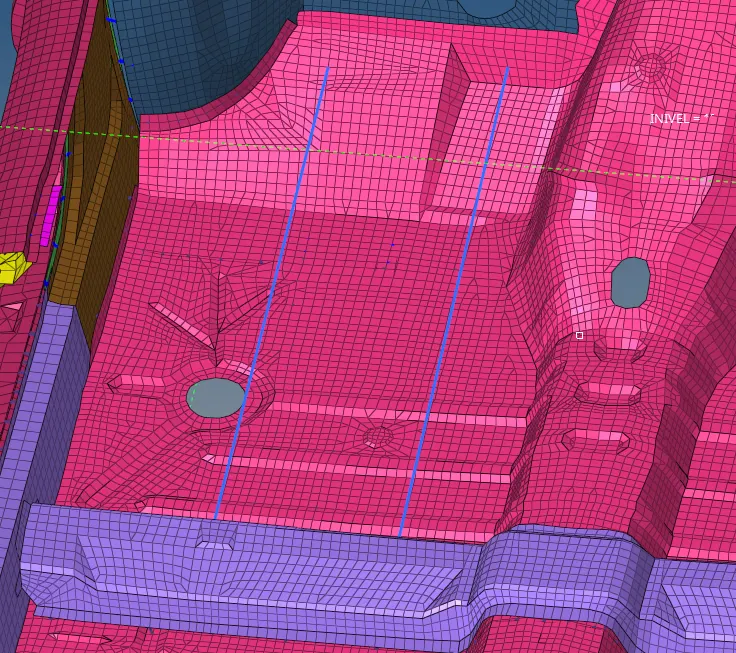
The below shown the spring of 2 nodes can be select in such a way that the selected nodes of opposite node will select and crate the spring element.

The element has been shown by selecting the that two nodes with the selecting the opposite node.
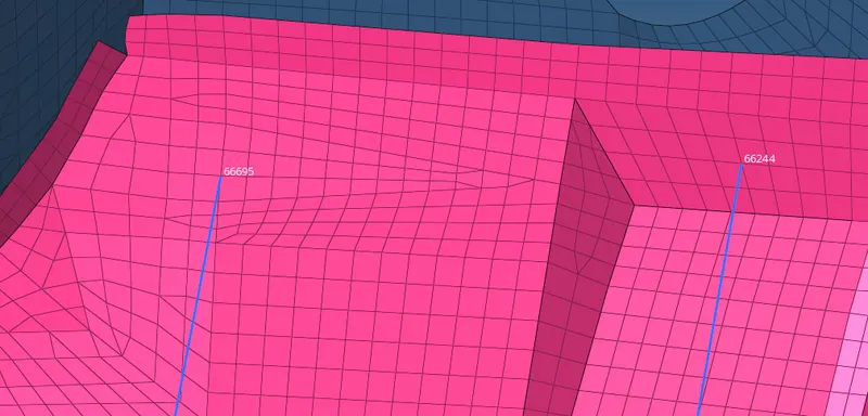
The given model has been shown the model has been crated the springs.
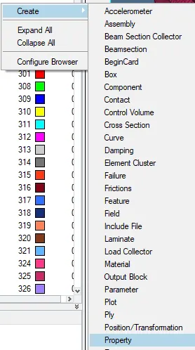
Creating the intrusion spring create the property for the springs.
The intrusion spring of property will crated , select the card image as the P4_SPRING as shown in below.
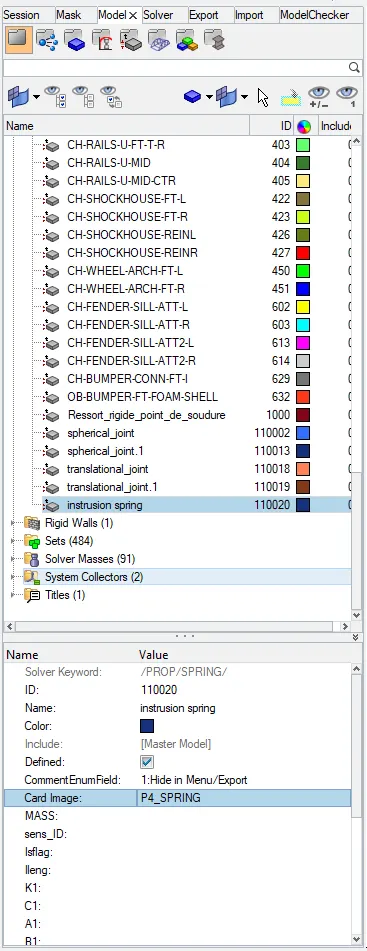
Assign the mass as the 0.001 and stiffness of the 0.001 as shown in below.
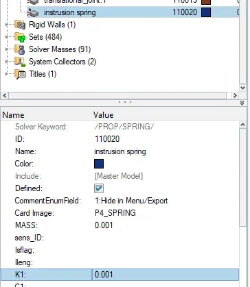
Assign that property in to the intrusion spring of model collector and assign as shown in below.
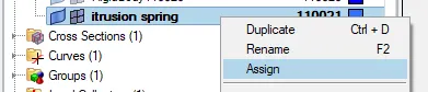
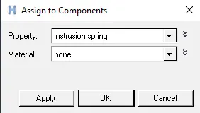
Select the property as the intrusion spring and apply, ok.
section- In this case we can introduce the sections to know the how much force can be passes through the component we can decide.
The section forces can be introduce in 8 components is of the bumper R/L, rail R/L,short gun R/L and the A-piller.
By selecting the solver browser and create for the SECT and SECT
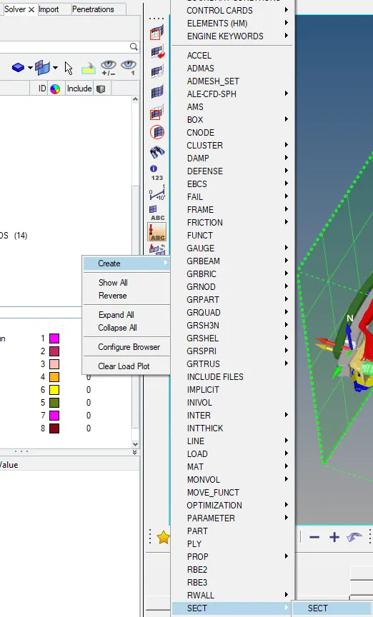
Select the nodes in such a way that first will be the origine node and second node will select will be direction to impact and third will be the free node to crate the section plane.
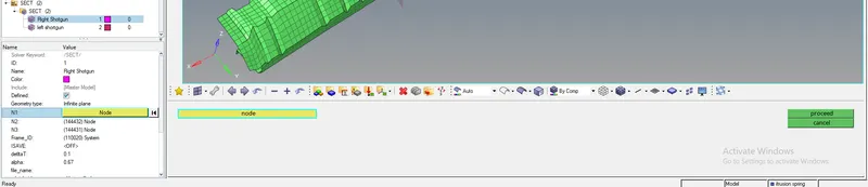
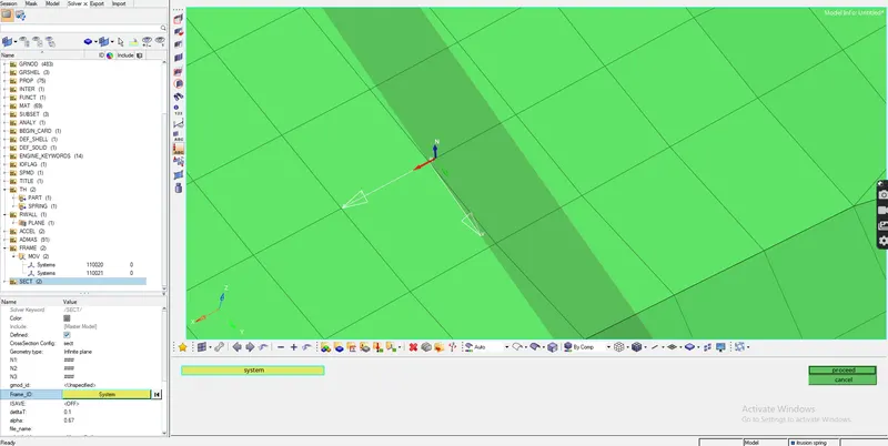
After creating the section specify the Frame ID by selecting the system and proceed. Similarly for the grshell also select it for the creating the nodes and select the elements surrounded by the section.
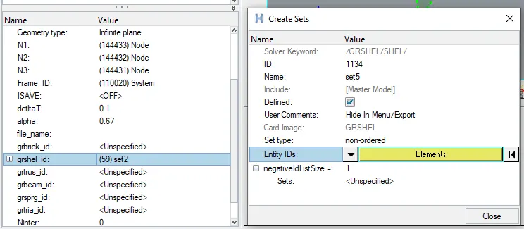
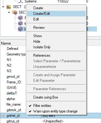
Similarly the section frame with selecting the system as shown in below.
Frame_ID > create/edit > select system>select system> proceed > close.
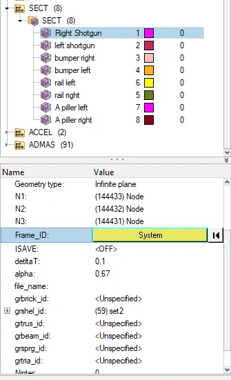
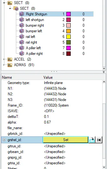
Given Delta= 0.1
Alpha= 0.67
grshell > edit > create > select elements> proceed > close.
TH- This will gives the time record file while simulation.
Plot the time hystory for the part, springs,section and accel of the component is selected specifically for each of the time hystory.
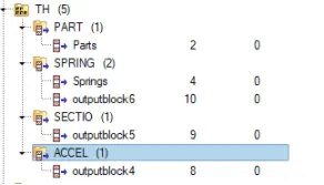
As shown in below the TH has been selected for the parts(73 component) , springs(73 component), sections (8 cross sections)and the accel (2 accelerometer)has been selected as shown in below.
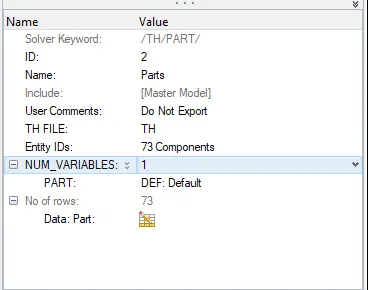
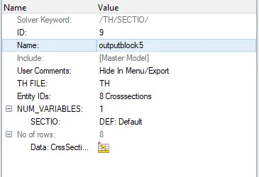
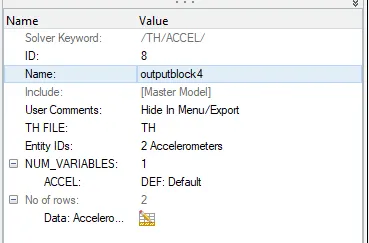
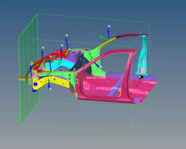
All case setup has been set into the car and it has been seems to be as shown in below.
After completing the all parameters has assign check for the unused and empty as shown in the tool bar as shown in below.
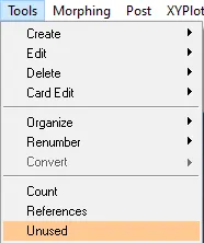
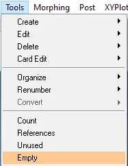
The delete up to it shows the no empty entities in selection and ok.

Modular Checker.
Similarly for the model checker in radioss block
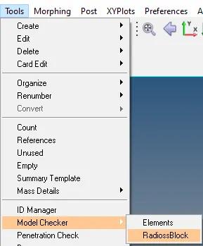
It will shows some error and warnings. The shown error can be solved and warning can be adjested/ neglected.
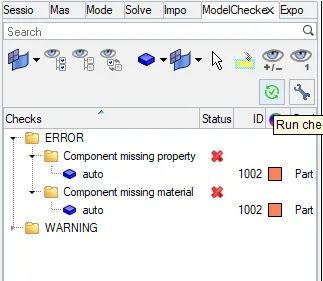
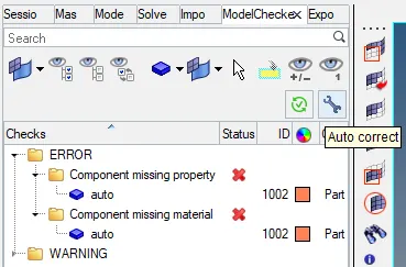
After solve the all the errors ready for the simulation save in the proper file and select the include the connection, select the option is for the _nt 4

After simulation has completed the final getting the results should be as shown in below.
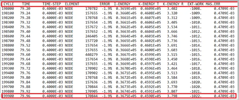
The energy error has been -2.1% has acceptable because there is range of the energy error has been accept up to the range of -15% to the +5.
The given results got from the simulation.
Cycle time - 199900
Energy error - -1.9%
Mass error - 0.47e-3%
Elapsed time = 9757.05 s
Run for the h3d file in to the GUI by selecting the hyperview and apply for the run file.
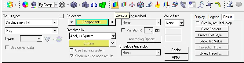
The select the file of h3d and apply in to the GUI and play for the animation.

After apply select the contour for the component and the displacement of the car body with side crashed with the side pole animation will be reflect on screen.
The below shown the while running the h3d file the animation for the displacement of car body and the deformation in the BIW model hit by the rigid body for the frantal crash will shows the deformation in the body will results to gets the deformation in shap has been gets the as shown in below. 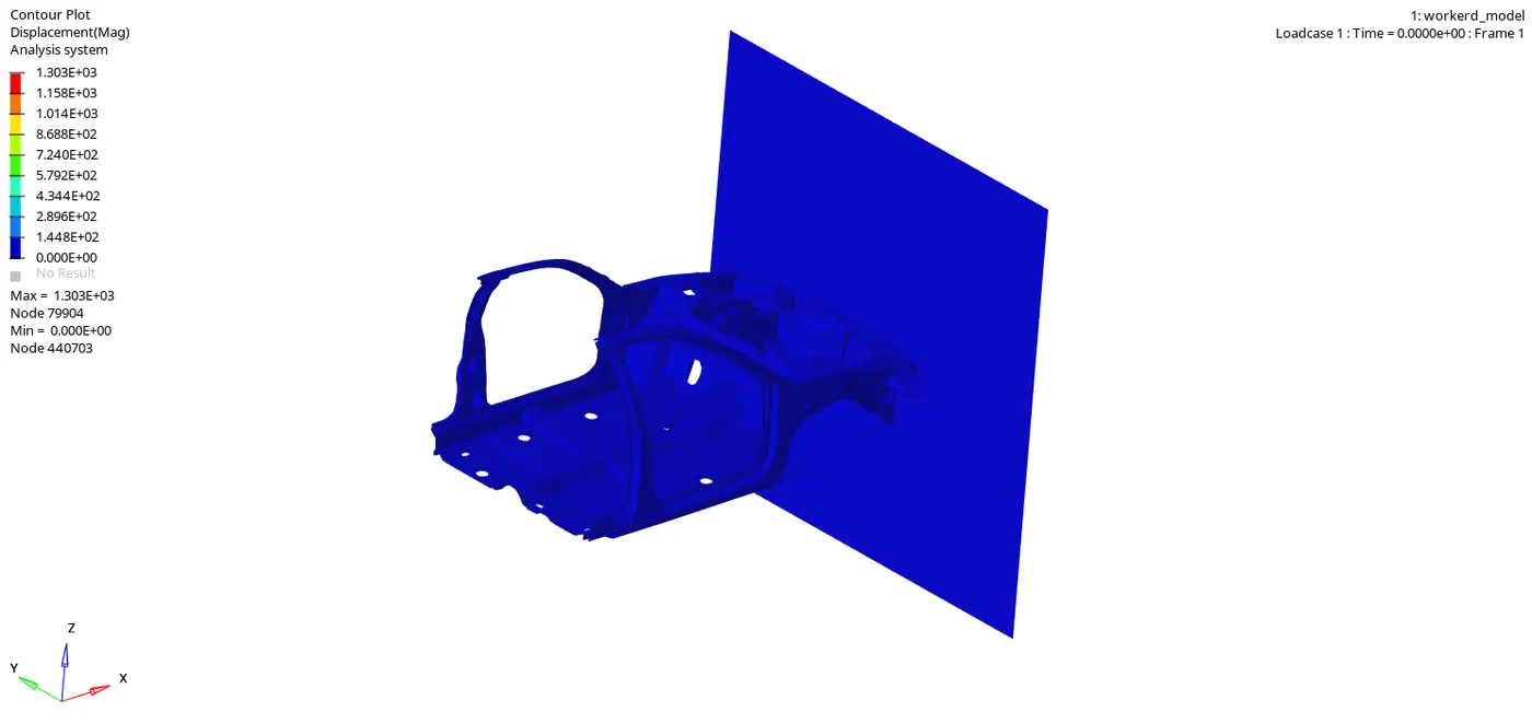
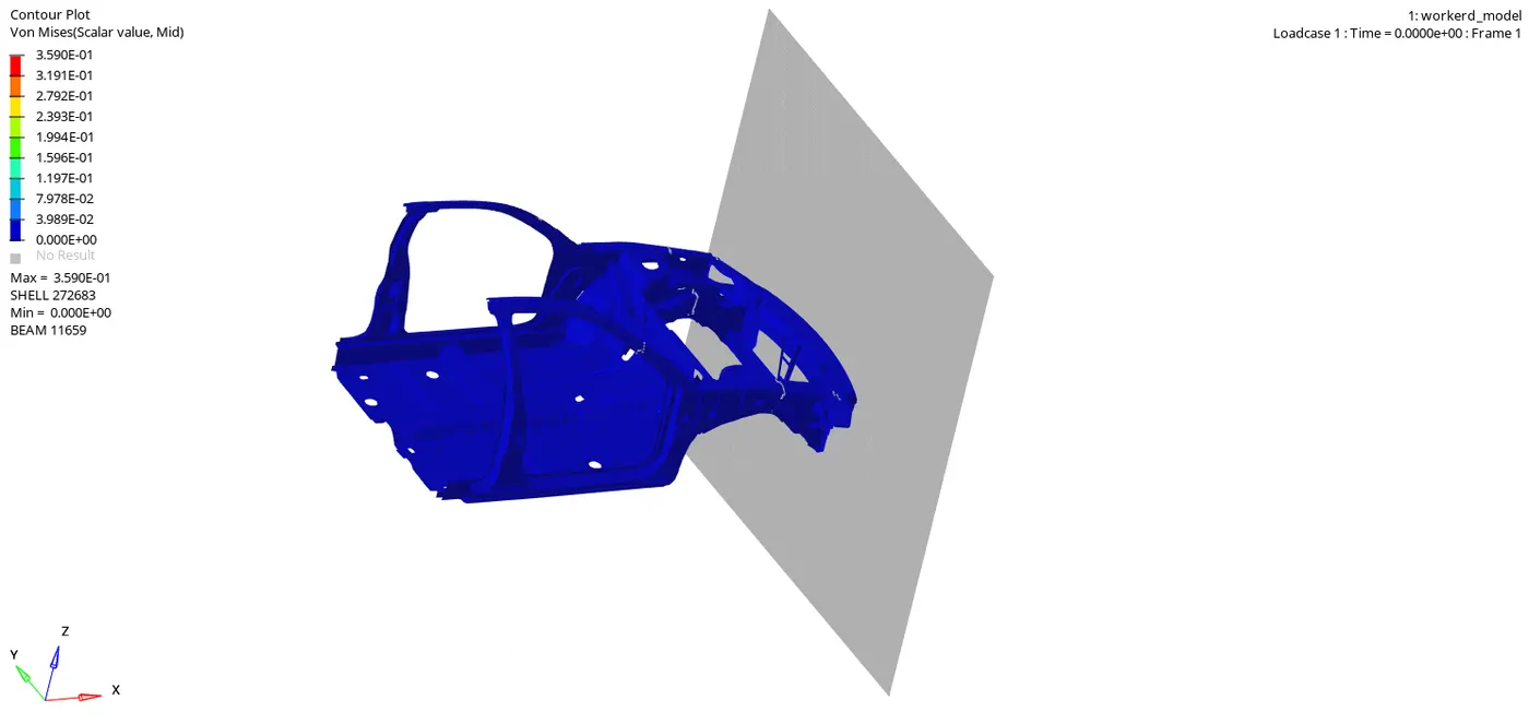
The animation file of the von mises has been shown in below the variable type of the stresses has been gives the results in the formation of the results as shown in below.
These following results plot the graphs in the hypergraph 2D as shown in below.
The import the T01 and selecting the globle variables of the selecting differnt energies and apply.

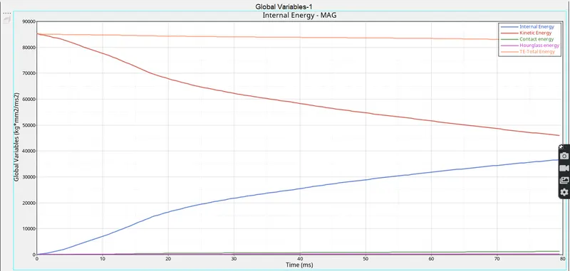
As global variables of the all type of energies can be plotted as shown in below
The below shown the global variables of the different energies can be plotted. takes place and its shown in below graph.
- The total energy has to be of resultant of all energies are to become the total energy and its shows the some energy error of 0.4590e5 was shoing but it has been acceptable.
- The kinetic energy has been decreasing from the higher energy to lower energy as shown in below figure. It means when the body will hit with the side pole the kinetic energy of the car has been decreases 0.1596e5 as per the record.
- The internal energy has been depends upoun the deformation for the car body. In graph there is internal energy has been starts from the origine, means no deformation at starting. After some time when the car body hit with the pole the body will get deformation.
- The hourglass energy has been not effects the because of the standerd parameters of fully intigrated nodes has been assigned in the parameters. It has been calculated 5% of the internal energy has been trated as the hourglass energy.
- The contact energy has been generated due to contact between the car body within the self contact.
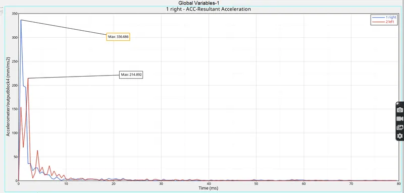
In the accelerometer by crating nodes in the right and left side the accelerometer has been have in results will be of 2 different caseas shown in below. The basically acceleration is created with the certain amount of the velocity with respect to time.
The right side of the accelerometer output will shows the 336.686 at starting and suddenly gets decreases due to the car model hit with the rigid wall. The acceleration will be drop.
The left side of the accelerometer is found as the 214.892 at staring and it will suddenly drops because of the rigid wall has the reson to decreases the acceleration of car model.
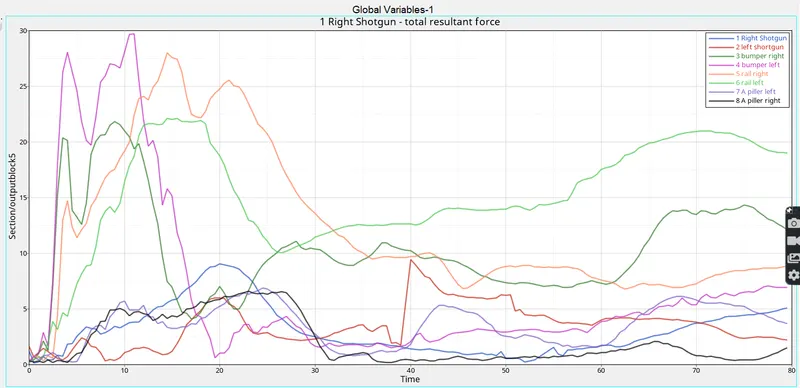
The section force of the bumper, rails, short guns and A-piller can be have created force due to impact as shown in below.
Bumper- The section force will create the model due to the crash and its is first effect in to this region so, in the graph it has been increases as shown in below.
Rails R/L- The rails will gets more section force because of the horizintal structre will absorbed the more compered to other sections.
Short gun - This is the third component to affect the % resultant forces for the component as shown in below.
A- piller- The piller has been shown the less effect of the resultant force compere to the all other resultant forces as shown in below.
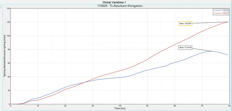
The intrusion springs are the introducing in the passenger seat and its has been selected with the specific nodes as shown in below.
The below shown the total spring elongation is of the springs are shown in the below graph.
The intrusions are there to decide the how much of deformation is undergoing for the car model during the car crash as below shown plot the graph.
The both intrusion has been shown below, intrusion 1 (66695) and intrusion 2(66244) has been showing the 120.297 and 77.241 as shown in below.
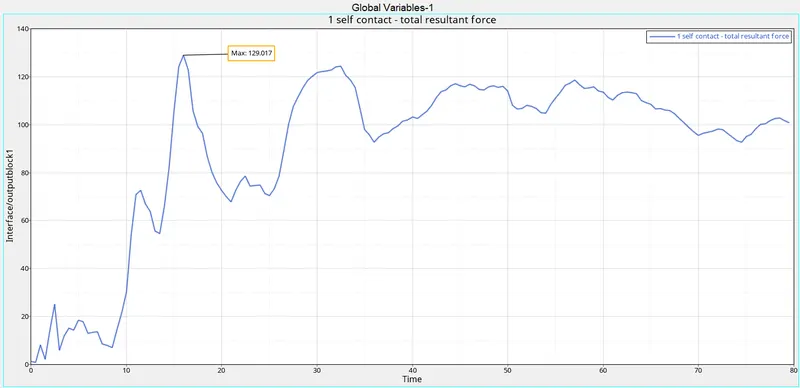
The contact the total resultant force is shown and in this case its due to elemental deformation as shown in graph. As per the graph initially not much contact force has been takes place. After some time intervals there is gradually incrases in the self contact of the BIW component as shown in below.
The self contact of the interface has been max as 129.057 as shown in below.
Results
The case setup for the frantal crash test has to achive.
To know the mass balancing for the given component.
The assigning the proper parameters for the TH, INVEL, BCS, skew, accelerometer and intrusions can be determined.
Conclusion
To understand the how to make the frantal crash simulation with assigning the suitable standerd parameters for the frantal crash to the given BIW component.
By analyse the the graph and understand the graph variation happened after simulation.
Compering the results with the graph and also the simulation maid the changes.
The real case this frantal crash has been takes place with the total assembly component with the assigning the initial veleocity to move.
It has been observed that there is min. deformation cabin and also min, intrusion at the given nodes in passenger compartment.