Week 6-Meshing of Hood Challenge
Aim - The given component by considering quality criteria, mesh the component and assign thickness for the individual component.
Procedure -
First we have to import the model from the folder
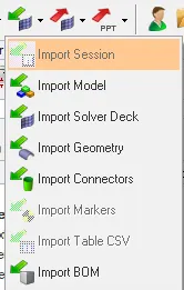
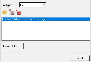
Import the model or select the file type IGES.
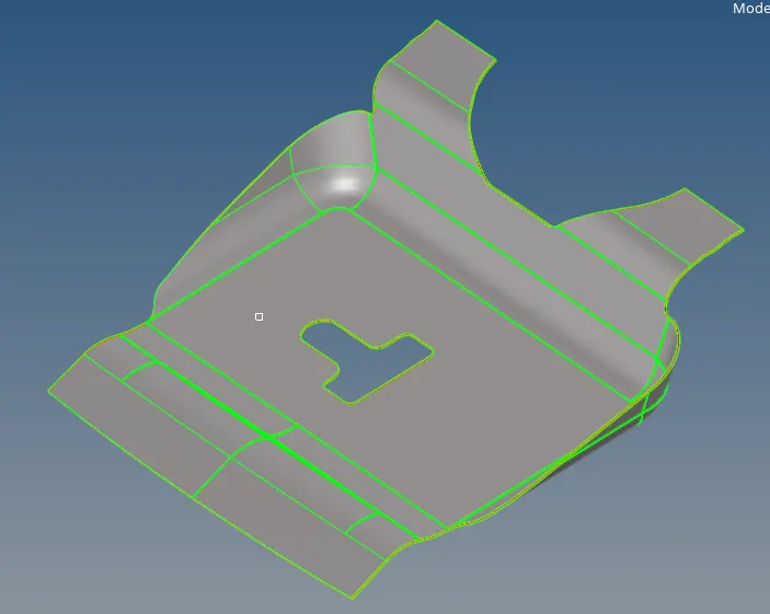
Delete solid component by selecting the delete and select displayed. select the delete entity. return

After deleting the solid part the component create midsurface.
Select the geometry and select the mid surface.

Select the extraction option, search the suitable option to select (skin offset). Auto extraction and select the displayed component. extract the mid surface ,return.

After taking midsurface the created the seperaate midsurface folder and rename the mid surface.
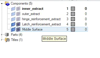
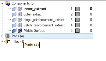
As shown below the component extract the midsurface.
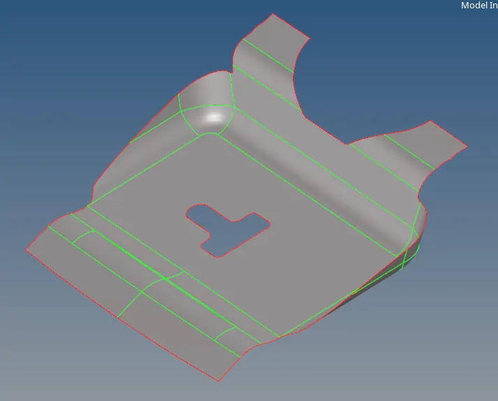
Extracted midsurface part do the autocleanup or manual cleanup option.
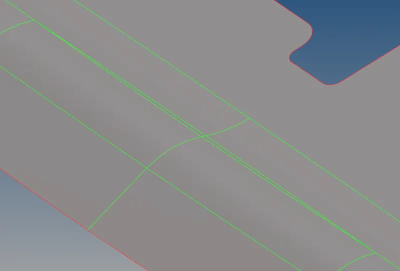
By manually remove the unnecessary lines, make use of toggle option and make the unnessary lines to be toggle.

As below shown the before toggle and after toggle lines from the midsurface.
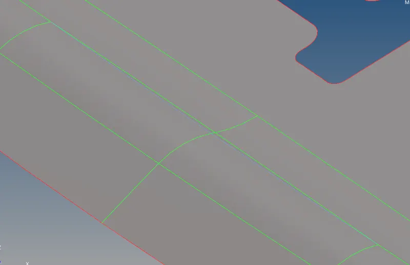
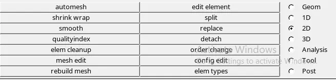
Ater finishing the geometrical clean up, assign quality criteriabefore meshing.
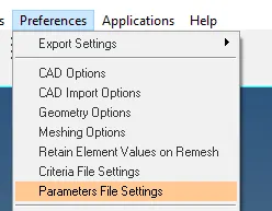
As per the given parameters select the element size, min. and max. of the quad and tria respectively for criteria.
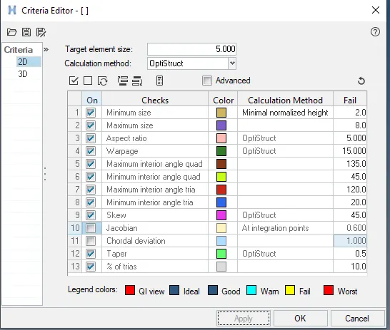
After asign the values apply and ok.
To mesh the midsurface component by selecting the surface of component. If surface is complicated to mesh split the surface and mesh.
The mesh is in the form of tria and quad elements. for plane surface the quad elements are prefered. One more thing should remember eleminete the max tria from the component. Because the tria elements are more stiffer than the quad elements.
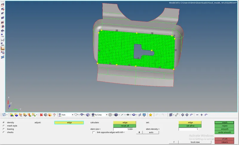
Remove the unnecessary quad and tria from the component. By doing this the elements get distrbed.
using the smooth option and mension itirations for the component and smooth it.

After meshing of each surface to be get better by using the quality index option.
In quality index the clean up tools are used

with help of quality index cleaner tools, select the requred option to get the good mesh.

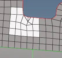
As per given below surface can have the improper quality in it.
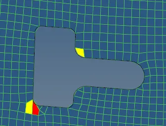
select the surrounding elememnts as shown in below and remesh that region to get the proper mesh.
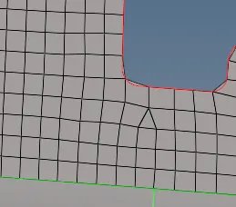
Similarly, the mesh can be get improper edge finising and rotational quads are created. Remove that elements by quality criteria
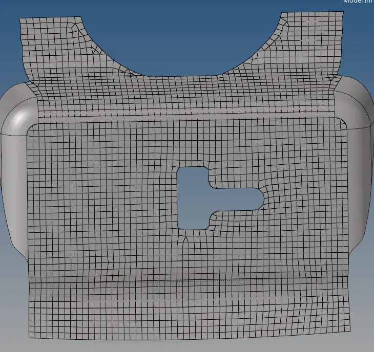
By using the smooth and optimization option remove the eleminate the edges.
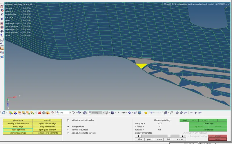
before that region becomes quality criteria.
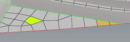
After using the quality criteria region the component becomes below shown.
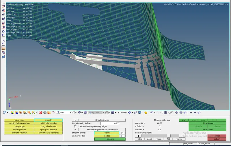
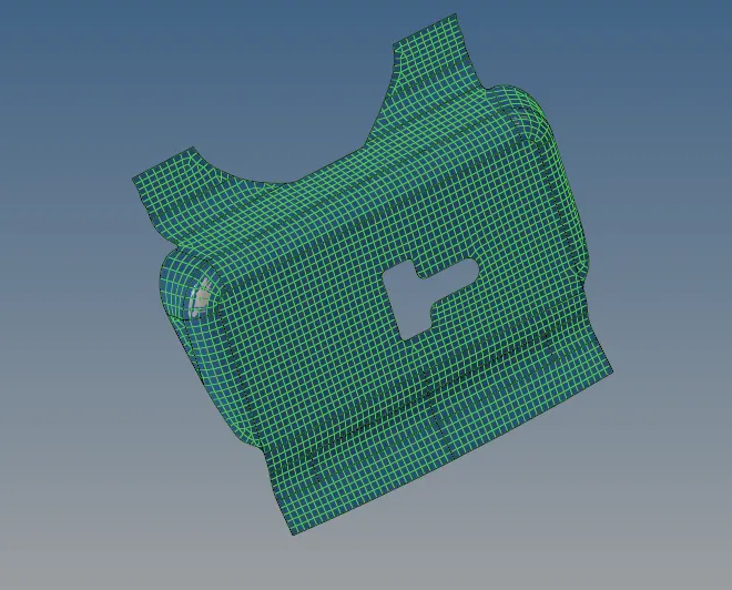
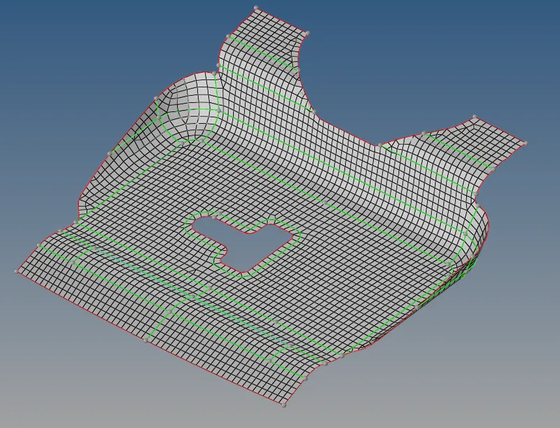
To remove the unnecesary edges by using tool and select the edges
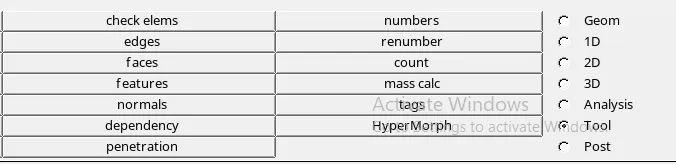
select the edes, select the component and mension tolerence of within 2 and find edges.

As below shown red lines the edes has failed to cinnect
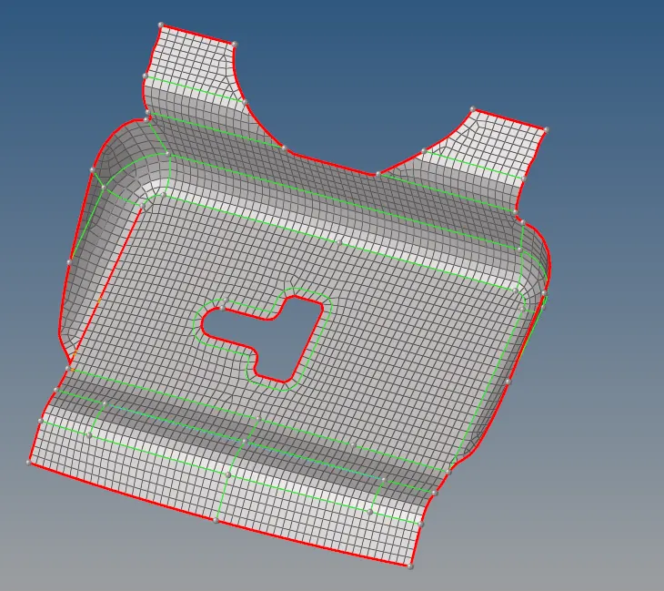
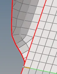
Make that all edges are equvalence. Do not get disturbed for elements to elements.
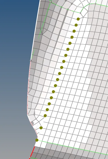
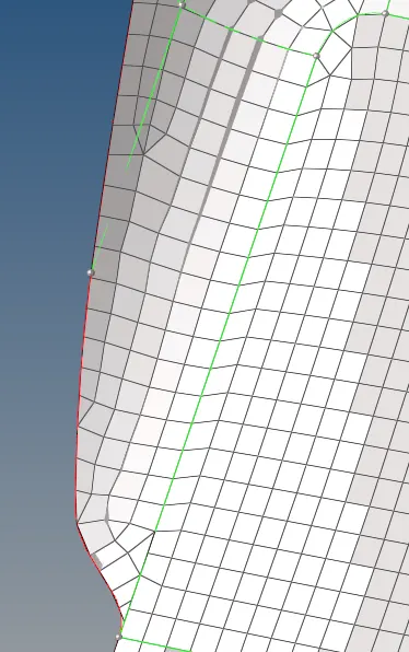
When the preview equvalence has done the select the equvalence and delete edges.
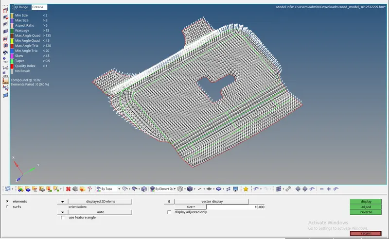
Find the normals to the surface or elements by selecting the component mention vectors as 20, display.

The normal for the component shown in below given.
Conclusion
By doing this understand the how to get midsurface,geometrical cleanup and proper meshing for the surface.
Aim - The given component by considering quality criteria, mesh the component and assign thickness for the individual component.
Procedure -
First we have to import the model from the folder
Import the model or select the file type IGES.
Delete solid component by selecting the delete and select displayed. select the delete entity. return
for this component, delete the the one component and mirror the component.
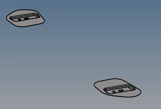
After deleting the solid part the component create midsurface.
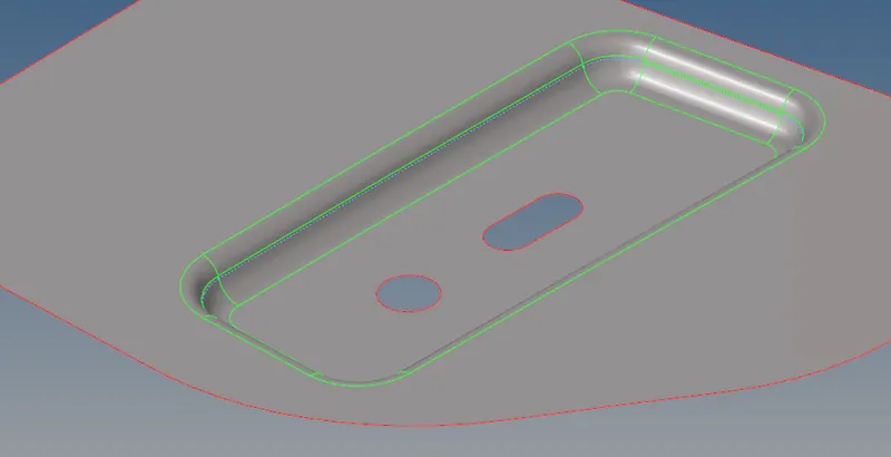
Extracted midsurface part do the autocleanup or manual cleanup option.
By manually remove the unnecessary lines, make use of toggle option and make the unnessary lines to be toggle.
As below shown the before toggle and after toggle lines from the midsurface.
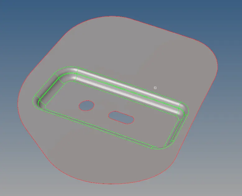
By using the split, component as per the requrement. Always the component should split from the corners for the component.
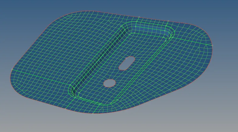
By using the smooth option the component will make to smooth.

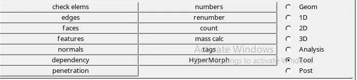
To find normal to the component select the tool and select normal.
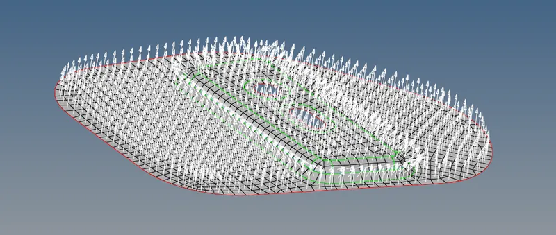
Find the normals to the surface or elements by selecting the component mention vectors as 20, display.
The normal for the component shown in below given.
Conclusion
By doing this understand the how to get midsurface,geometrical cleanup and proper meshing for the surface.
Aim - The given component by considering quality criteria, mesh the component and assign thickness for the individual component.
Procedure -
First we have to import the model from the folder
Import the model or select the file type IGES.
Delete solid component by selecting the delete and select displayed. select the delete entity. return
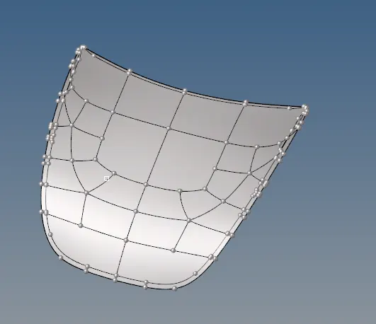
Delete the half surface and do the mesh for half surface.
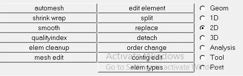
Select 2D, select the automesh and mension the element size as 5 and mesh type is mixed.

Do the proper mesh for the surface.
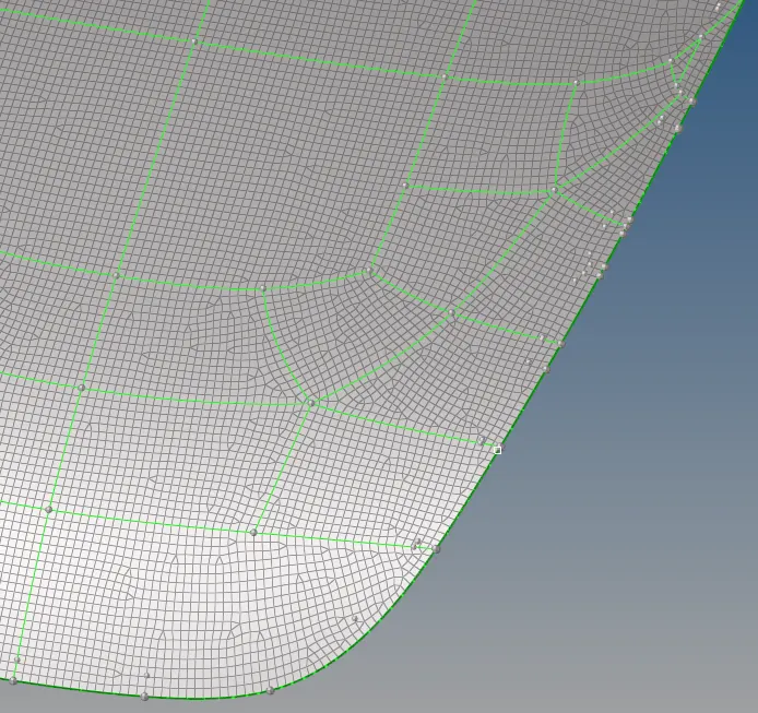
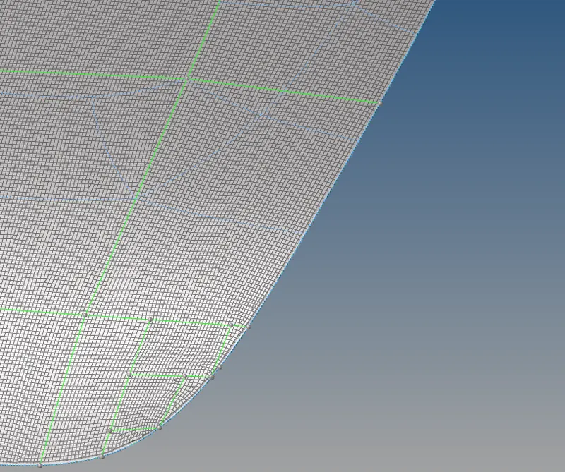
Delete unwanted lines and make the proper split for the component.
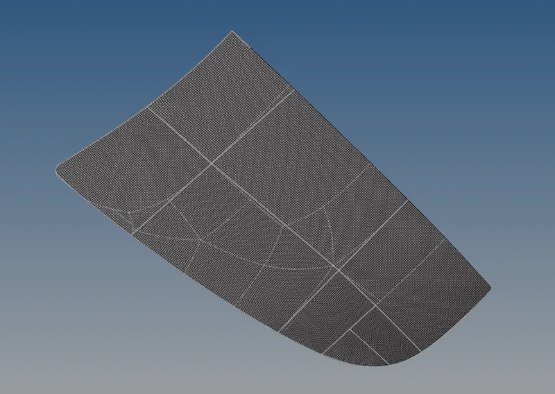
As below shown the surface is properly splitted.
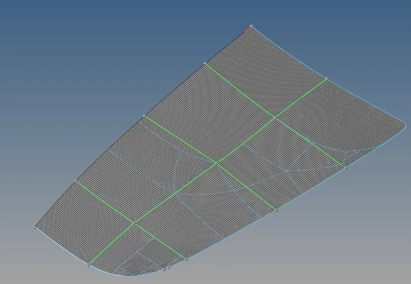
Do the meshing by selecting the split surfsce one by one.

After done meshing remove trias as much as and the surface gets smoothened. By using the quality index command the component make proper mesh flow
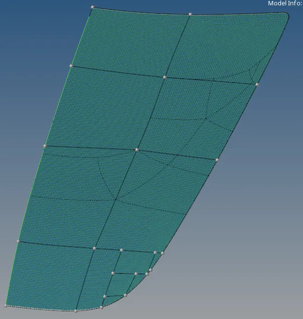
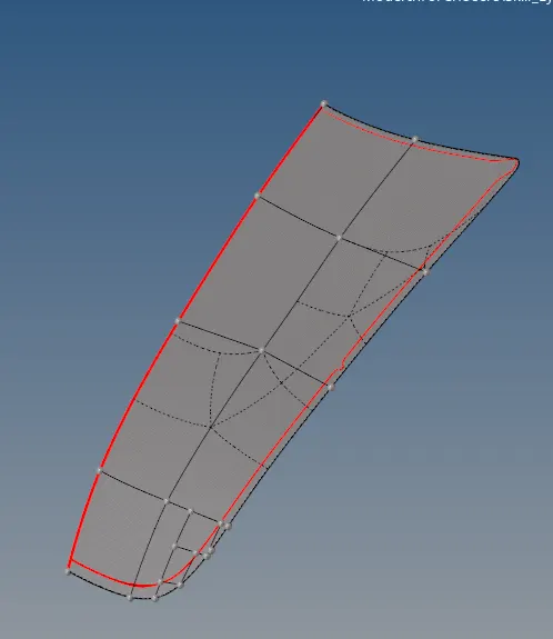
For half part of component is to make complete copmonent by using the reflect option.
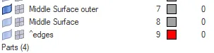
Hide the mid surface of outer componenet and select the tool. select the reflect.

Select the surface of the componenet, select the displayed component and select axies to reflect the surface.

Select the surface and axies.

Sake that slected surface gets duplicated the surface.

Select the original component .
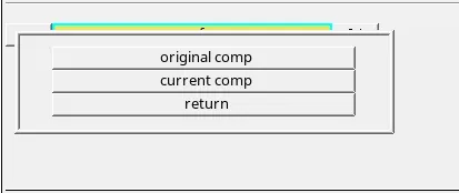
Select the axis and select the base point and reflect the component.
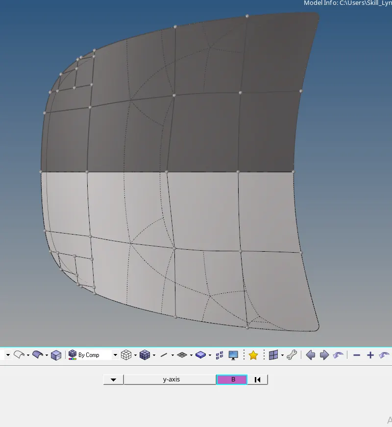
The reflect component will shown below shown.
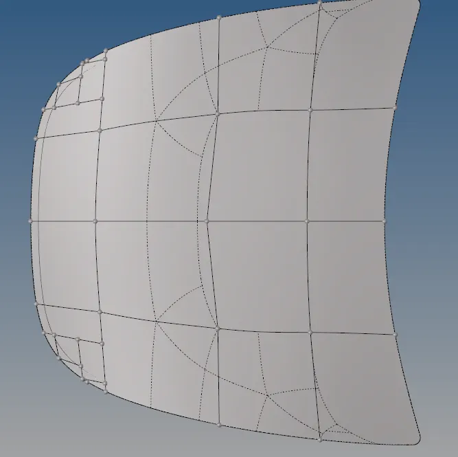
Similarly for the elements also, there is same procedure to follow.

Select the elements and select displayed.
Select by original comp.
The final component becomes on meshing as shown in below.
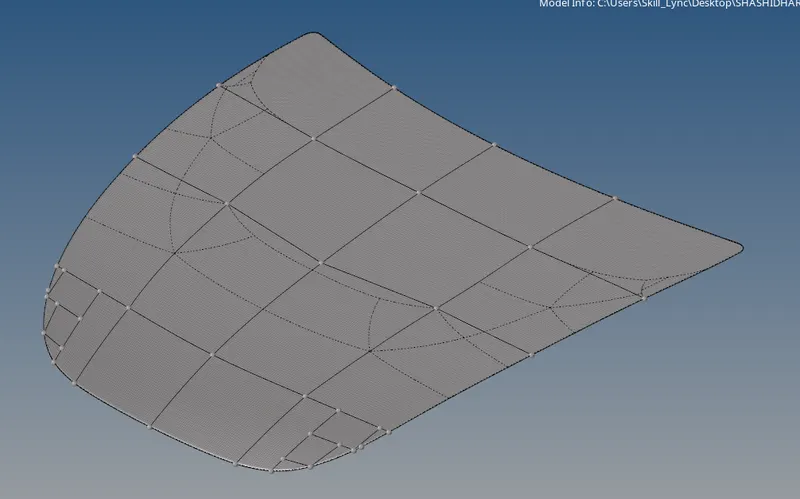
The component, find the edges for the given component
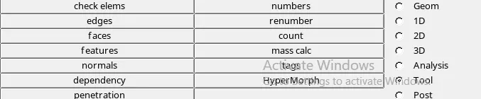
Slect the tool and select edges.

Select the total component and give the tolerence of within 2 find the edges.
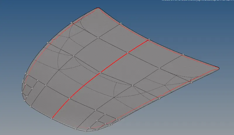
After finding edges select on get preview equiv to equivalance.
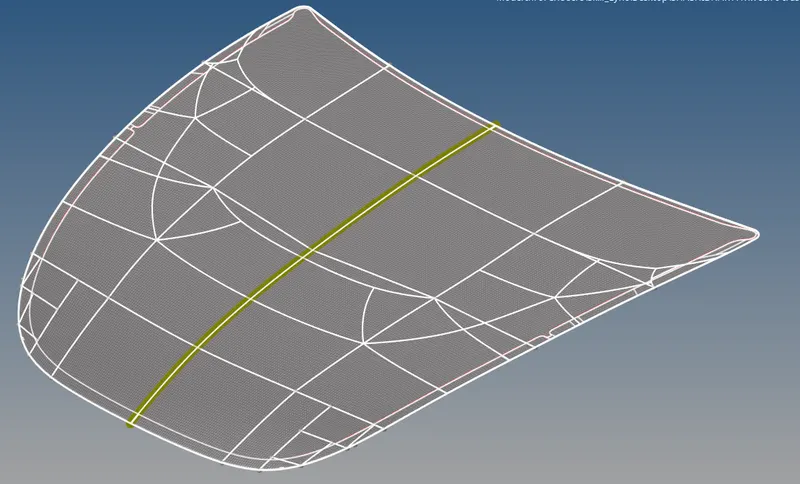
Now the equivalence done. Delete the edges for the component.

The final component becomes like below shown.
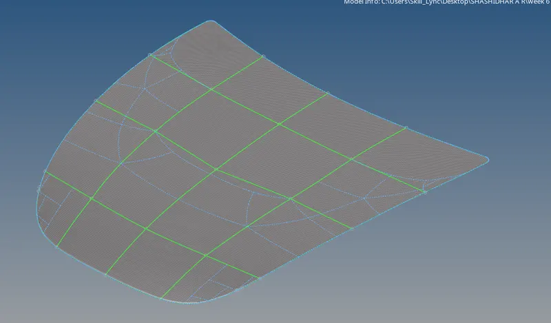
Conclusion
By doing this understand the how to get midsurface,geometrical cleanup and proper meshing for the surface. How to use the equivalence the elements and how the component will gets reflect by using the various commands.
Inner component
Aim - The given component by considering quality criteria, mesh the component and assign thickness for the individual component.
Procedure -
First we have to import the model from the folder
Import the model or select the file type IGES.
Delete solid component by selecting the delete and select displayed. select the delete entity. return
After deleting the solid part the component create midsurface.
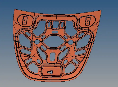
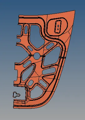
The above component is symmetriv on both the sides so, delete the one side of component as shown above.
Extracted midsurface delete the unnecessary lines from the component
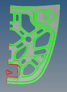
By manually remove the unnecessary lines, make use of toggle option and make the unnessary lines to be toggle.
Similarly, As below shown fig. the before toggle and after toggle lines from the midsurface.
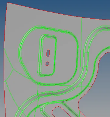
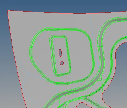
If some surfaces are improper to capture for mesh so, for that problem split the line and create surface to mesh .
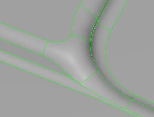
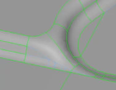
For curved surface, mesh by slecting the curved surface and do the proper meshing.
Select 2D, select the automesh and mension the element size as 5 and mesh type is mixed.
As much as eliminate the tria from the surface. make quade element.
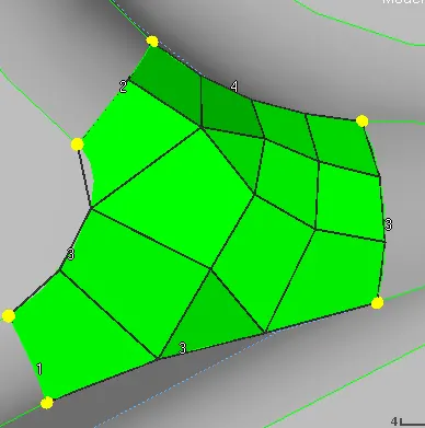
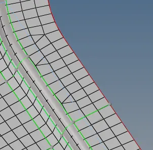
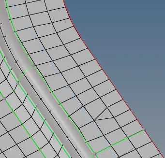
After meshing the surfcaes the possibility for created the opposite tringles and tringles on edges so,
we can prevent as much as shown below drawing.
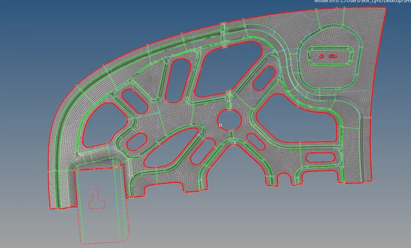
The component, find the edges for the given component
Slect the tool and select edges.
Select the total component and give the tolerence of within 2 find the edges.
For half part of component is to make complete copmonent by using the reflect option.
Hide the mid surface of outer component and select the tool. select the reflect.
Select the surface of the componenet, select the displayed component and select axies to reflect the surface.
Select the surface and axies.
Take that slected surface gets duplicated the surface.
Select the original component .
Select the axis and select the base point and reflect the component.
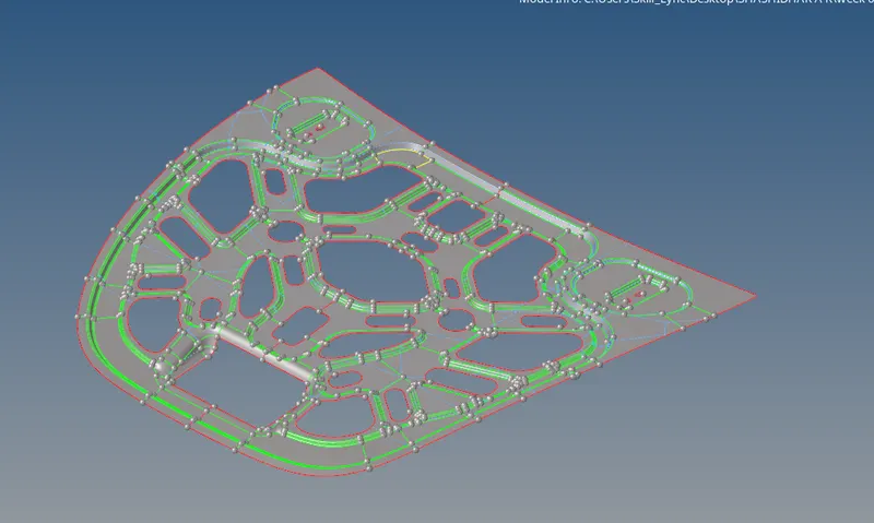
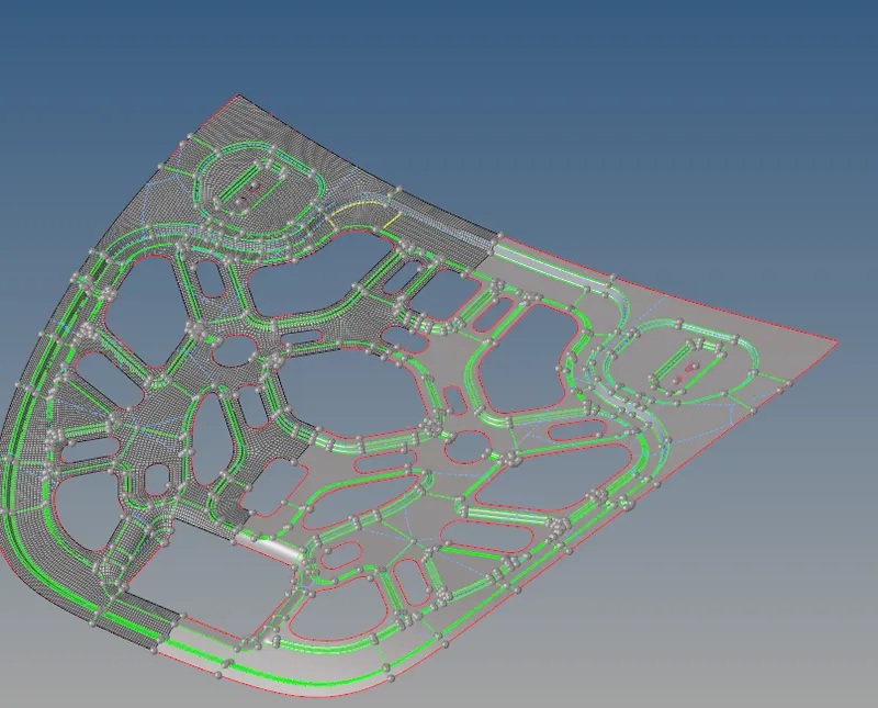
Similarly for the elements also, there is same procedure to follow.
Select the elements and select displayed.
Select by original comp.
The final component becomes on meshing as shown in below.
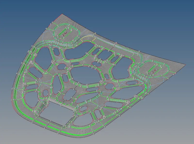
After finding edges select on get preview equiv to equivalance.
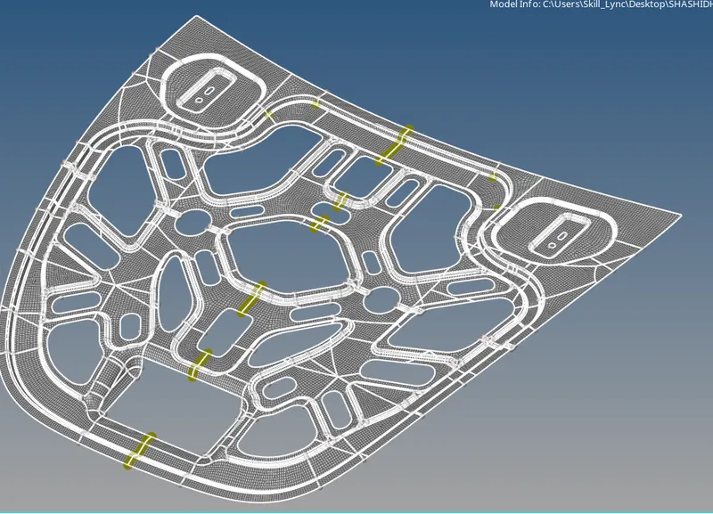
Now the equivalence done. Delete the edges for the component.
The final component becomes like below shown.
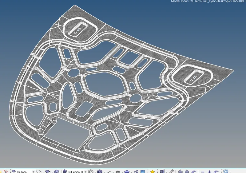
Finally got the component.
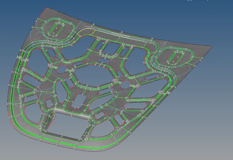
Conclusion
By doing this understand the how to get midsurface,geometrical cleanup and proper meshing for the surface. How to use the equivalence the elements and how the component will gets reflect by using the various commands.