Week 1 Stress Concentration on a Plate with hole
Aim - To perform the static structure analysis for the plate with holes.
Procedure- open with the ansys work beanch and the beloe shown the tool box with GUI is given.
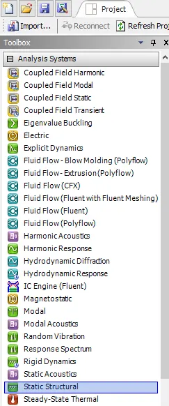
Double click on the static structural and it will show the project schematic as shown in below.
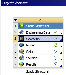
Next the open with the geometry will popup with the geometry window as shown in below.

By using the line draw the geometry for to get the 3D model.
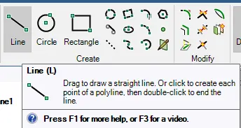
Draw the gemetry by using the given parameters in the statement as shown in below.
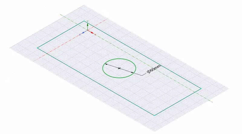
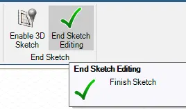
After done with the sketch select the end sketch editing as shown in below.
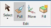
Select the pull option and select with the pull direction.
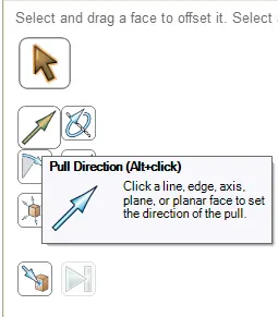
Select with the pull direction as shown in below.
Select the hidden direction arrow to pull as shown in below.
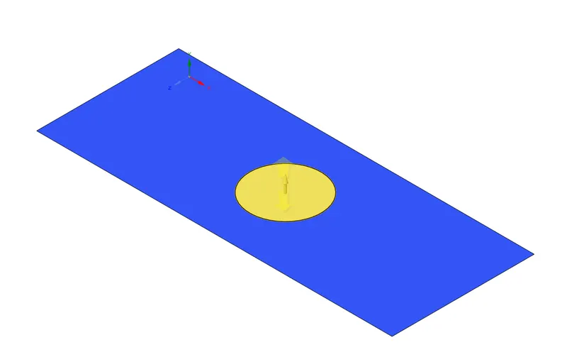
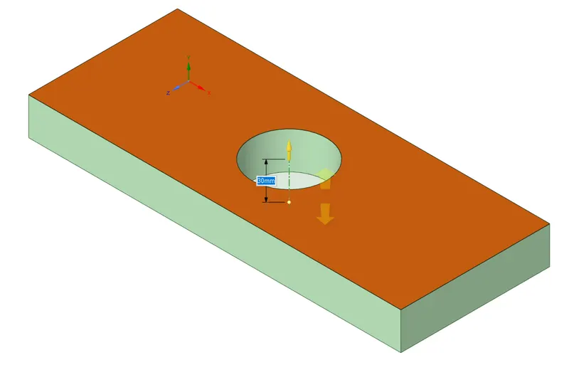
Pull the surfcae and mention up to the 30mm as shown below. close the geometry.
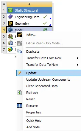
Double click on the model can be update the model.
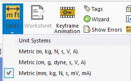
Set the unit the system as per the given in the statement.
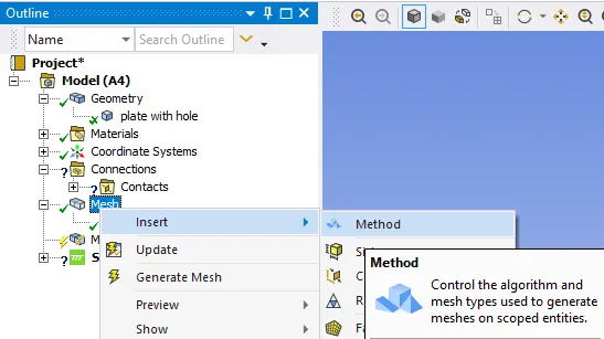
Select the mesh make the right click
Mesh>insert>method.
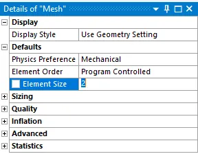
Select the element size 2 mm and in this case select the select the 5mm. because of the elemets ristriction for the student edition. Its shown in below statistics.
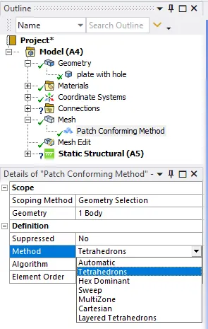
Select the patch confiorming method as the tetrahedrons and select as the 1body as shown in below.
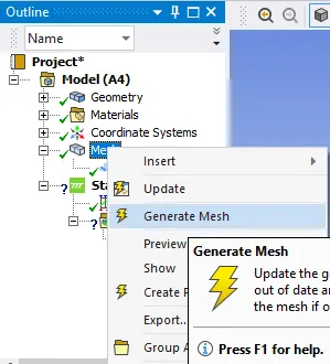
Select the mesh and select generate the mesh as shown in figure.
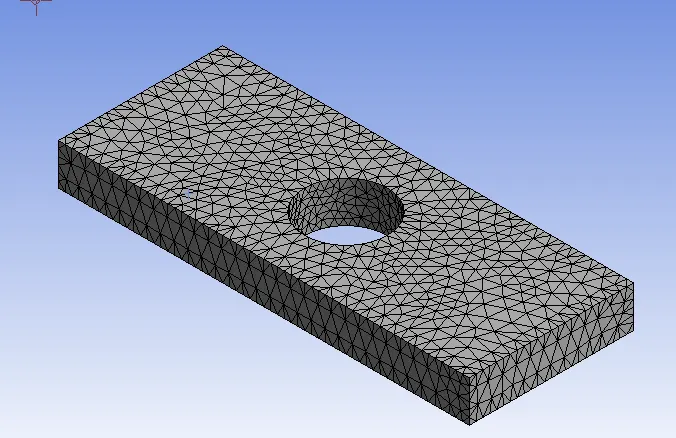
The tetrahydron eleements ctration as shown in below.
Select the static structure right click and select the surface and fixed support.
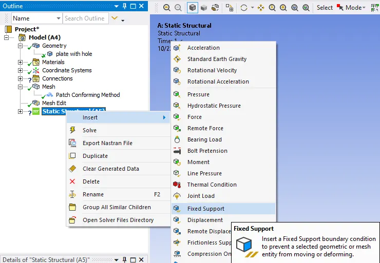
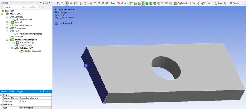
After selecting the fixed end and its shown in below.
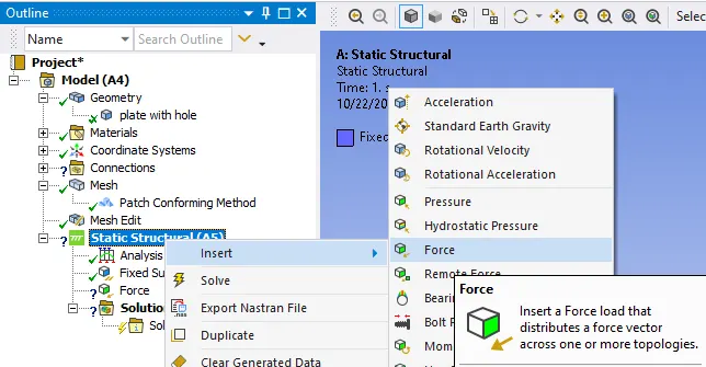
In static structural insert as the force and it is shown in below.
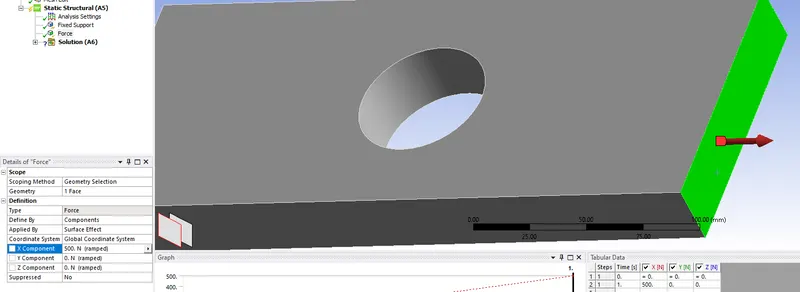
Select the face for force and create the force of 500N.
Define by> composites> x components> 500N > ok.
After assigning the fixed support and force solve the static structural solve as shown in below.
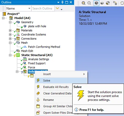
It will take some time for to solve/simulate and after simulate we can do for the deformation,strain and stress.
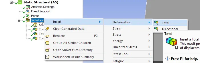
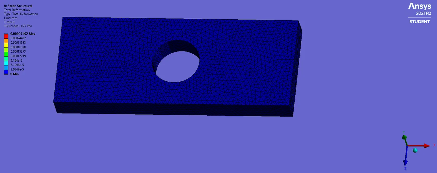
Total deformation of the image has been shown in below.
The max. total deformation of material as shows 0.0002792mm at the end and min at the fixed end.
For equivalent strain (von-mises) select and it shows as shown in below.
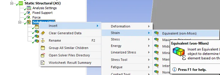
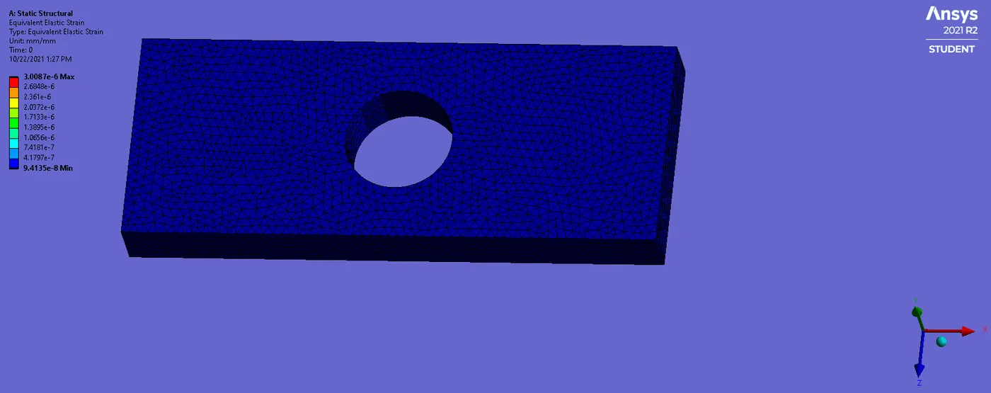
The static structural of equivelent strain has been shown max of 3.0087e-6 and min of 9.4135e-8 at the center of hole as shown in below.
Similarly for the Equivalent stress of the plate has been selected as shown in below.

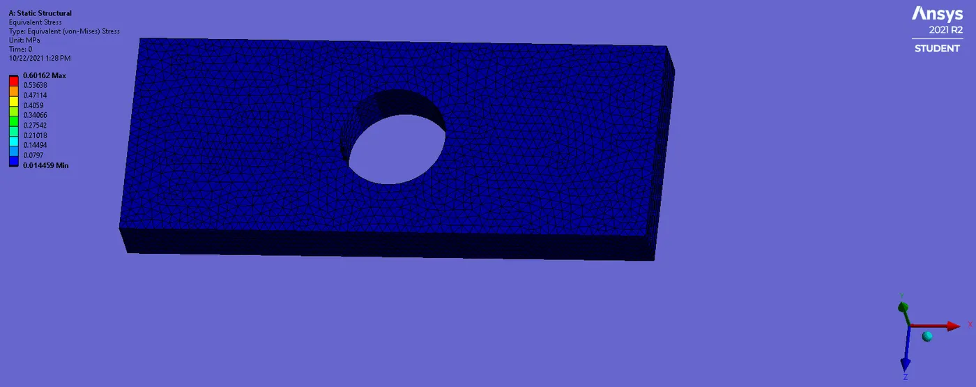
The stress concentration has been at the center of the plate have hole as max. has been recorded of 0.60162MPa and min is 0.014459MPa at the center of plate as shown in below.
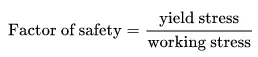
This stress is accepble or not by checking the FOS. The getting FOS for structural steel is 250MPa.
Compering with the case1 this can be acceptable for the static structure, its within the FOS.
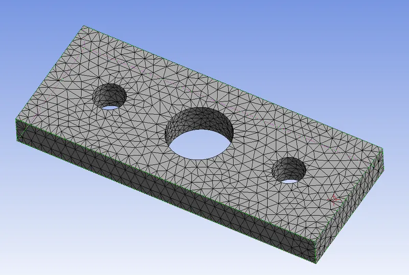
Similarly for the case 2 of the plate with the hole to maintaining the same procedure only extra to make 30mm holes as mesh.
The model is of the tetrahydral elements as shown in below.
Assigning the all fixed support and force and the solution has been solve as shown in below.
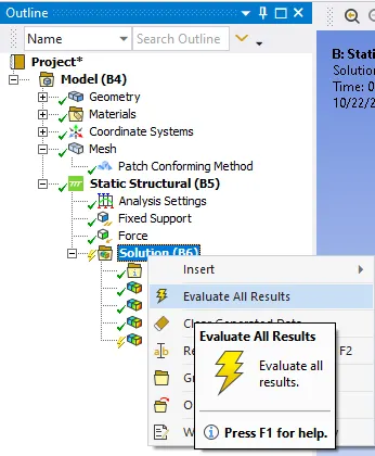
After solve evaluate the all results from the solution.
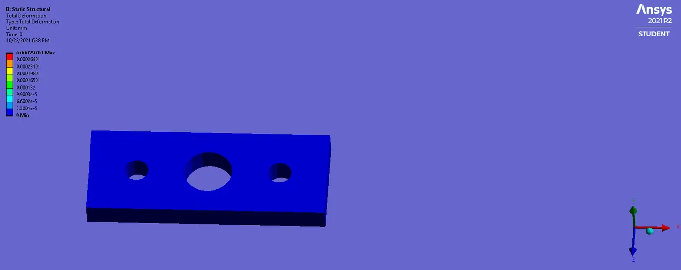
The below shoen the total deformation of the plate with three holes. The total deformation for this ststic structural max. of 0.00029701mm reached at the end and min deformation will be the fixed end.
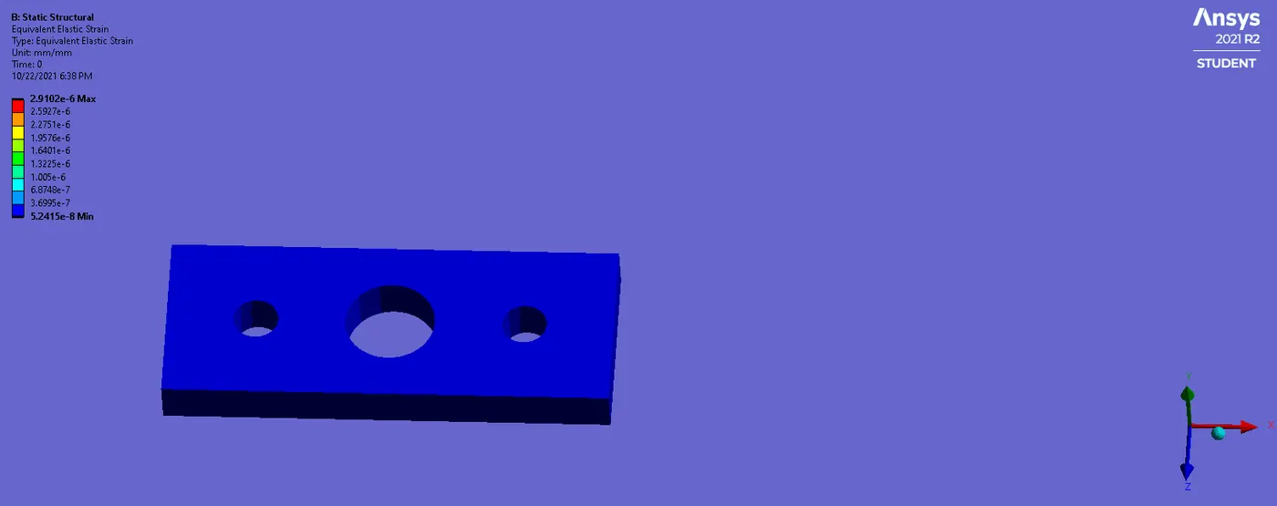
The strain concentration has been at the center of the plate have hole as max. has been recorded of 2.9102e-6 and min. of 5.241e-8 at the center of plate as shown in below.
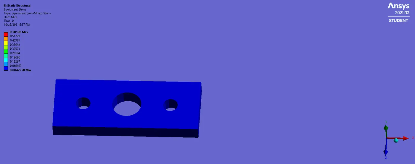
For the max equivalent stress has been found 0.58198MPa and min of 0.0042958 at the middle holes as shown in below.
This stress is accepble or not by checking the FOS. The getting FOS for structural steel is 250MPa.
Compering with the case1 this can be acceptable for the static structure, its within the FOS.
Results
The below shown the compering the case 1 and case 2 of the results we got from the solution.
| Total Deformation(mm) | Equivalent strain(mm) | Equivalent stress (MPa) | |
| Case 1 | 0.0002792 | 3.0087e-6 | 0.60162 |
| Case 2 | 0.00029701 | 2.9102e-6 | 0.58198 |
In result of case 1 has of max. stress of the 0.60162 MPa and the applied force is to be of 2.792e-4mm with the strain of 3.0087e-6 mm and for the same in the case 2 is of max stress is 0.58198 MPa and the deformation is of 2.9701e-4 with strain of 2.9102e-6 has been recorded.
compering the both cases of case 1 is of plate with center high stress with the min. deformation, For the case 2 plate with the three holes has been high deformation with having the low stress (hoel has been introduce ) with respect to each other.
From the Analysis point, case 2 is better than case 1 as in the case 2 has design failuer due to higher stress on the central hole is avoided.
From the manufacturing point, case 1 is better than case 2 has two more holes introduced so, it increases the manufacturing tooling cost complexity.
Conclusion
In this cases we can conclude that to avoid failuer of the plate due to the force applied case 2 is the better design case1 can be chosen if the applied force is lesser and does not end in fracture. Its helps to reducing the manufacturing tooling cost/ complexity.