Week 2 Bevel Gear Challenge
Aim- To perform the static structural analysis for the given bevel gear model.
To perform the grid dependency test for the given model with different sizes of the mesh.
Introduction
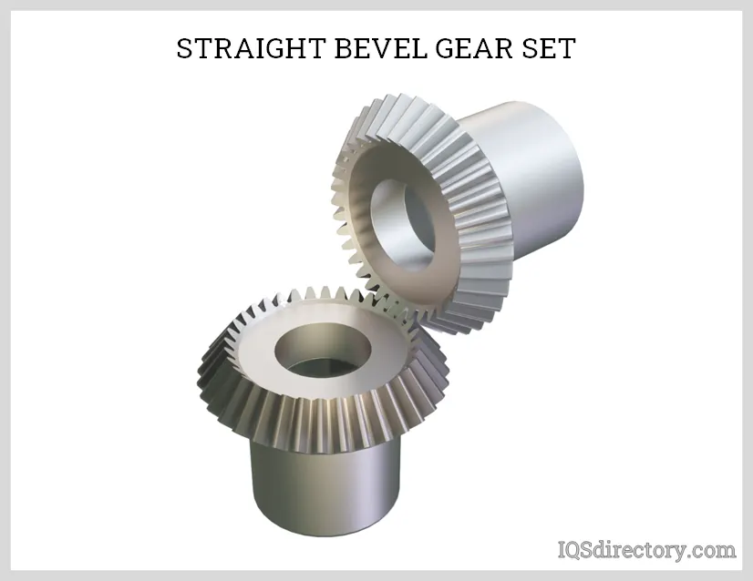
Bevel gears are gear where the axes of the two shafts intersect and the tooth-bearing faces of the gears themselves are conically shaped. Bevel gears are most often mounted on shafts that are 90 degrees apart but can be designed to work at other angles as well.
The biggest benefit to using bevel gears is their mechanical advantage; you can increase or decrease the tooth ratio between the drive and any accompanying wheels to correspondingly increase or decrease the force.
These bevel gears are used to transmit rotational motion at right angles, whereby the two axes of the gears intersect. This type of gear is therefore often built symmetrically. The movement consists of rolling without sliding two Bevels, hence the name.
Bevel gears are used to connect shafts whose axes lie at an angle to each other, although in most applications the shafts are at right angles. The tooth profile is basically the same as used for spur gears except that the tooth gets progressively smaller as it approaches the apex of the projected cone.
- Transmissions.
- Conveyor systems.
- Speed reducers.
- Engines and mechanical transportation systems.
- Gear pumps and motors.
- Machining tools.
The most fundamental method of checking the mesh quality is to refine a mesh until a critical result such as Equivalent stress does not change significantly with each refinement (i.e.it converges). This is a Grid dependency test.
where. the analysis begins with a coarse mesh and it is refined to finer mesh for each run until the results do not change significantly and depend on the grid size anymore. As the grid or mesh, size approaches zero. the approximate solution is almost equal to the actual solution.
The aim of this test is to find the optimum mesh size for the solution. where it is neither too coarse to produce inaccurate results. neither is too fine. where it will consume a lot of computing effort and time.
The grid independence test is a process used to find the optimal grid condition that has the smallest number of grids without generating a difference in the numerical results based on the evaluation of various grid conditions.
There are different mesh refinement techniques are used which have advantages and disadvantages and some depend on the experience and technical expertise of the FEA analyst. These techniques include Reducing the element size. Increasing the element order. Global Adaptive mesh refinement. local adaptive mesh refinement. manually adjusting the mesh. Time adaptive mesh refinement. wavelength adaptive mesh refinement. etc.
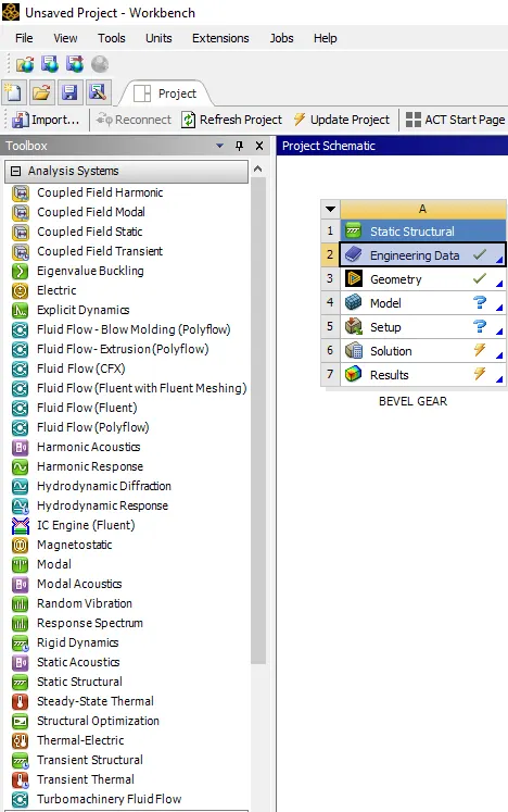
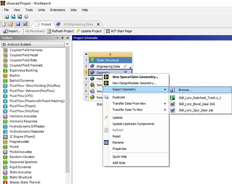
Procedure- To start the simulation by opening with the Ansys workbench.
Select the static structure from the toolbox as shown below shown.
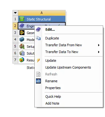
Update the engineering data as shown below.
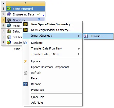
Also import the geometry from the browse with the updated geometry.
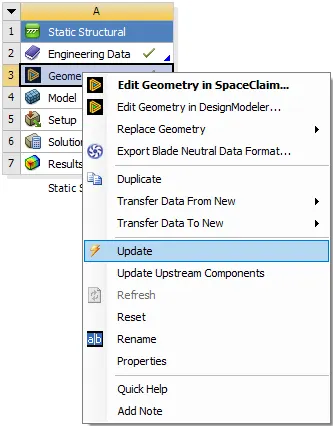
After updating the geometry double click on the model, its popup with the model window.
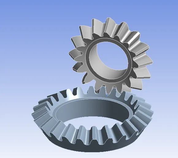
The bevel gear model seems to be as shown below.
Give the proper name for the shown gear by selecting in model with small and big as shown below.
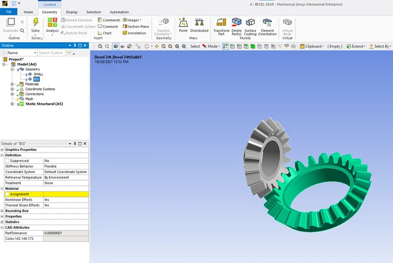
Use the material as the structural steel for both small and big bevel gears as shown below.
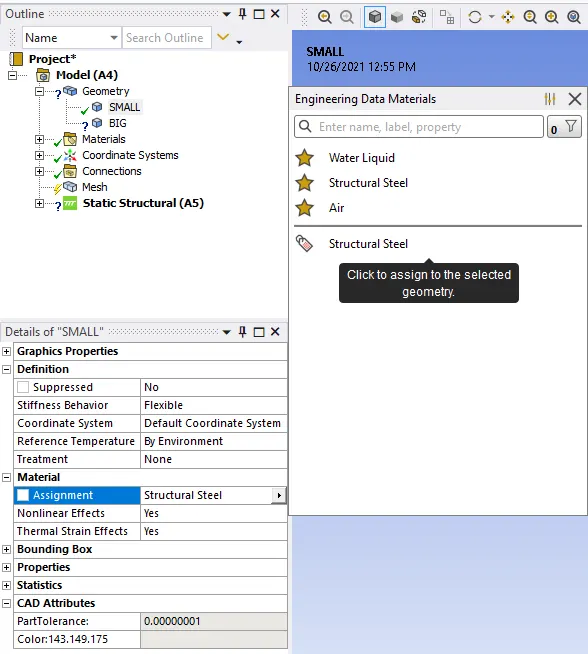
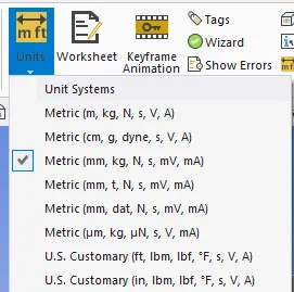
Select the proper unit systems for the given analysis results.
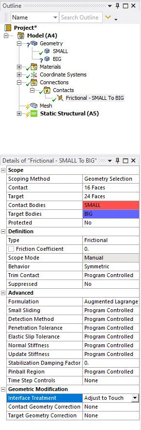
To create the contacts as the frictional and select all teeth faces w.r.t contact bodies and target bodies as shown below.
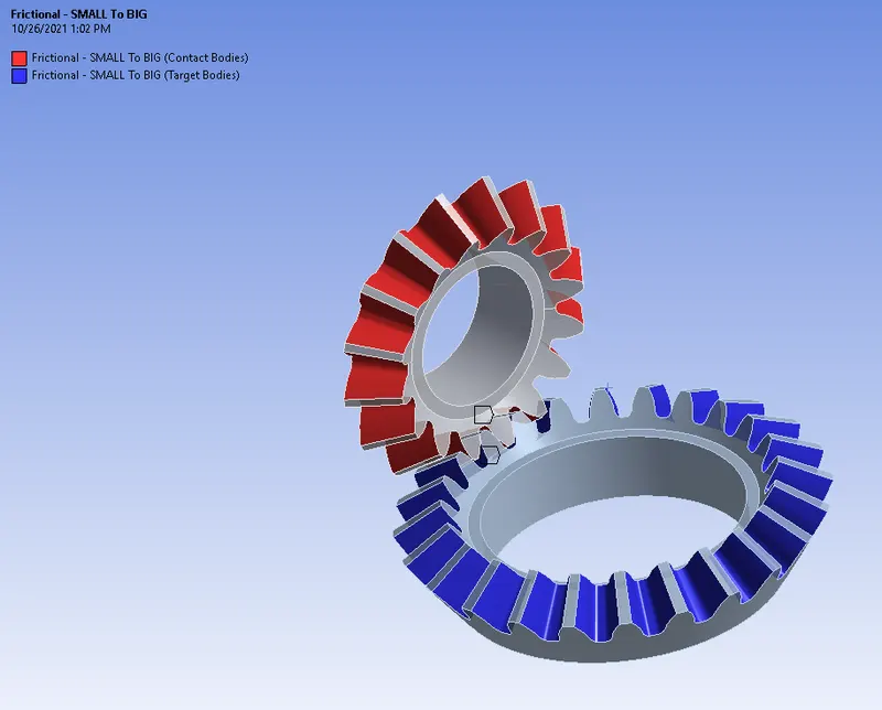
The below shows the selected gear teeth of contact bodies and target bodies.
Similarly, create the connection for the 2 joints.
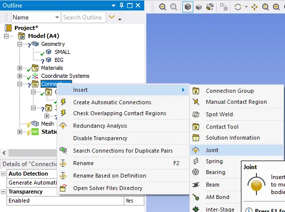
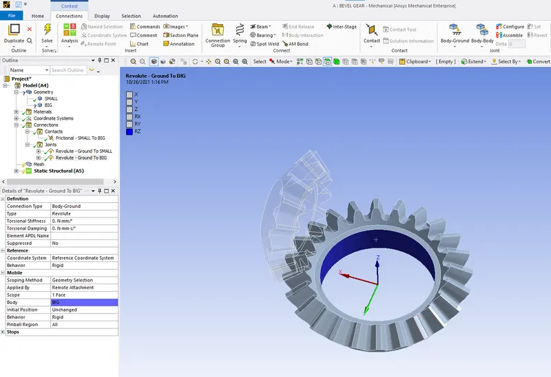
Select the type as the revolute of ground to small and ground to big.
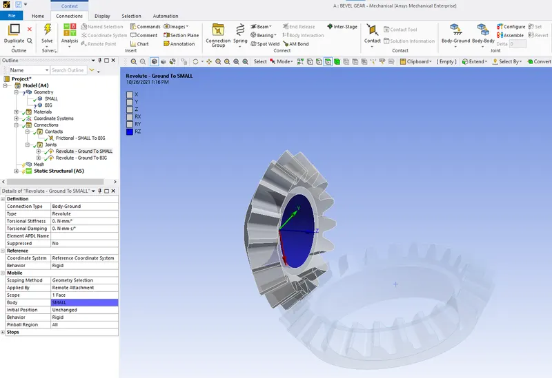
Also, select the proper scope and body for the given model.
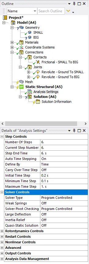
The analysis settings are set properly of step control as shown below.
Insert the static structural load for both gears.
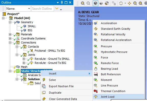
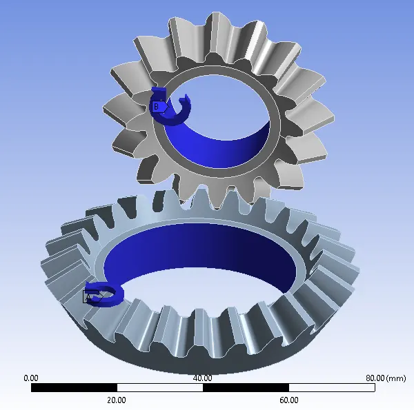
It will decide the axis of rotation on their axis also in the opposite direction to each other. The direction is to have one is clockwise and another is the anti-clockwise direction to choose.
Do the meshing for the 2 types we can select.
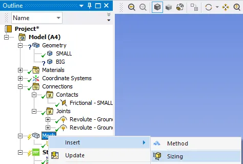
The below shows the element size select as 6mm and face sizing is taken as the 1.75 as shown in the video.
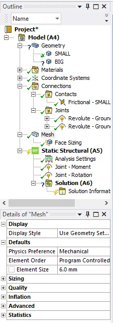
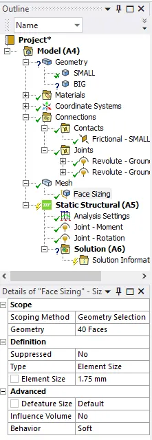
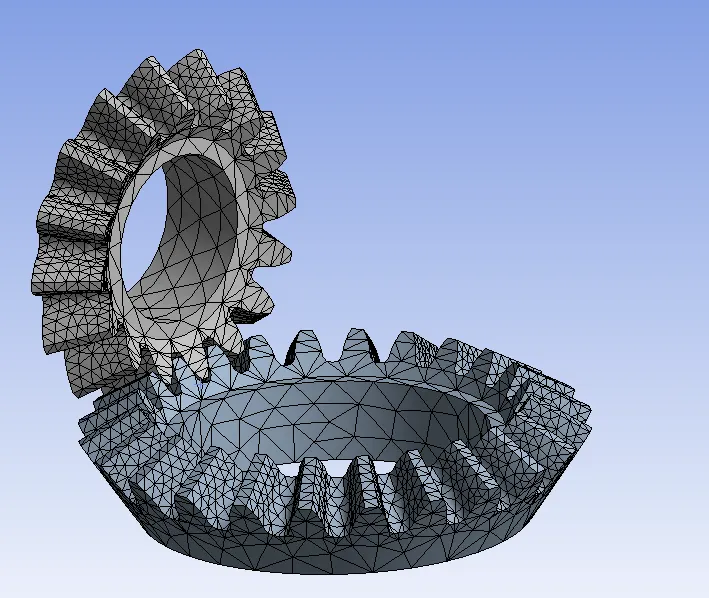
By selecting the elemental size and face sizing for the gear teeth generate the mesh as shown below.
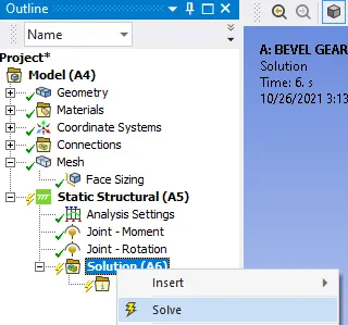
After selecting all static structural parameters it has been solved.
The solution information of total deformation, equivalent elastic strain, and equivalent stress.
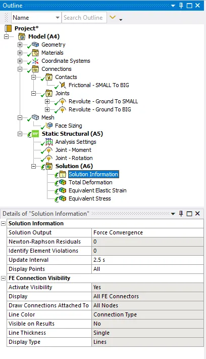
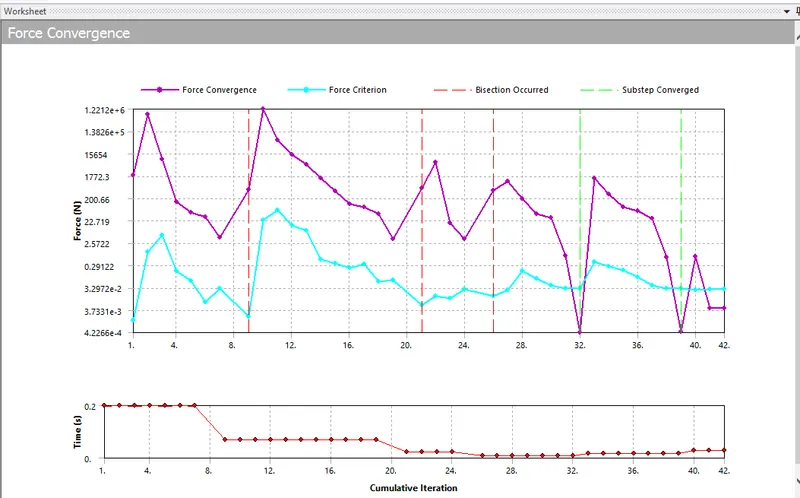
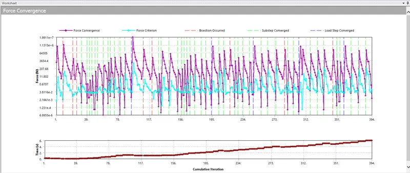
For solution, information selects the solution output as the force convergence as shown below.
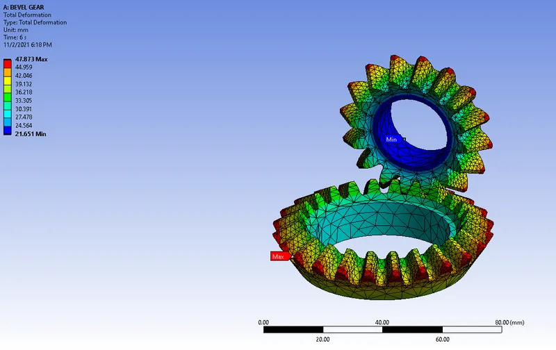
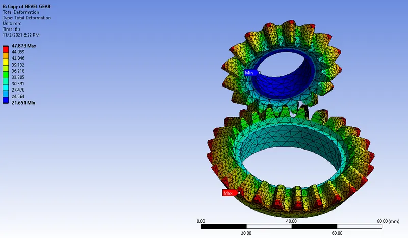
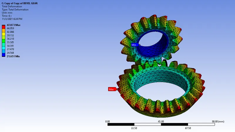
The total deformation of the is seems to be the max. 47.873mm and min is 21.651mm as shown below.
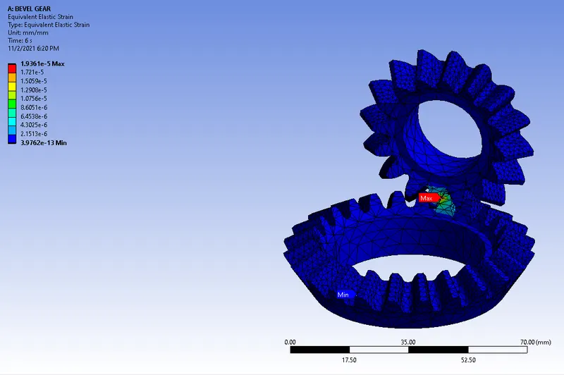
The bevel gear of elastic strain has to be max. at 1.9361e-5mm and min at 3.9762e-13mm as shown below.
The maximum stress is due to the min. 3.431MPa and min. of 6.409e-8MPa as shown below.
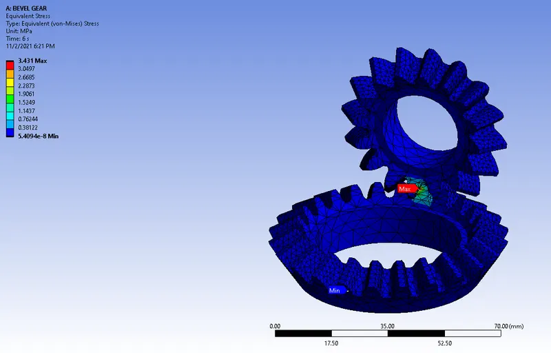
Then select the max. 3.431MPa prob for these shown below.
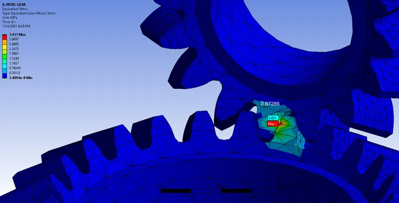
Case 2 Element size of 5mm
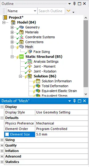
Similarly, for case 2, the only difference is element size has been 5mm maintained as shown below.
The force convergence graph is shown below.
The total deformation of the is seems to be the max. 47.873mm and min is 21.651mm as shown below.
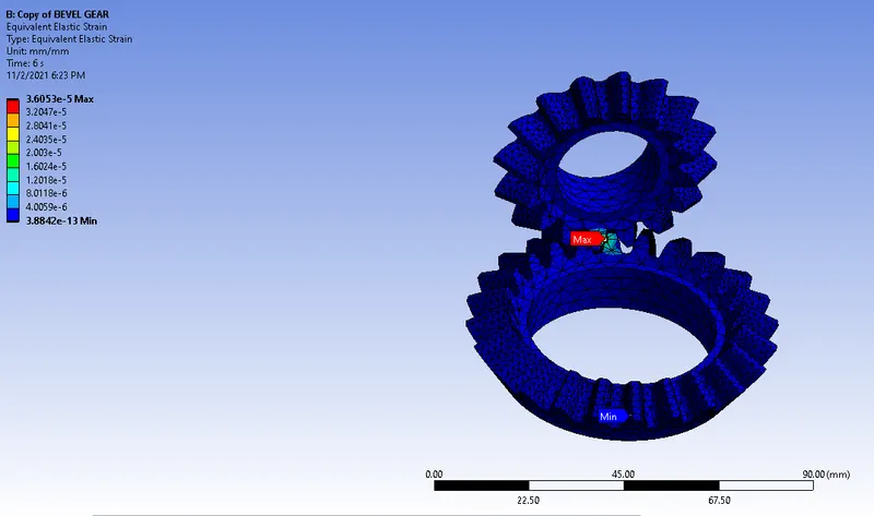
The bevel gear of elastic strain has to be max. at 3.6053e-5mm and min at 3.8842e-13mm as shown below.
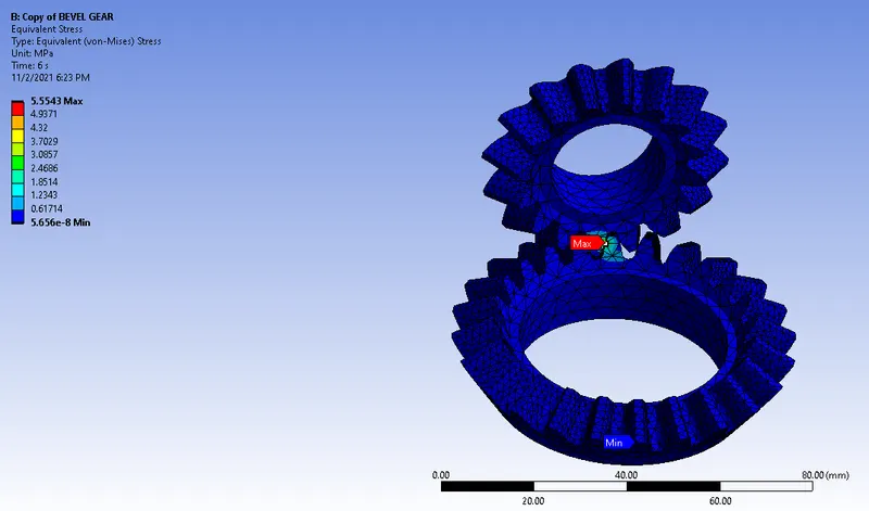
The maximum stress is due to the min. 5.5543MPa and min. of 5.656e-8MPa as shown below.
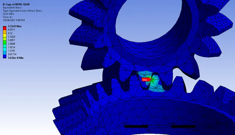
Then select the max. 5.5543MPa prob for these shown below.
Case 3 Element size of 5mm
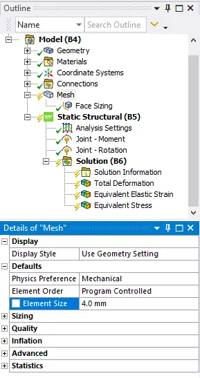
Similarly, for case 3, the only difference is element size has been 4mm maintained as shown below.
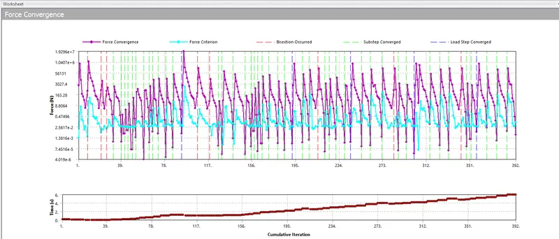
The force convergence graph is shown below.
The total deformation of the is seems to be the max. 47.873mm and min are 21.651mm as shown below.
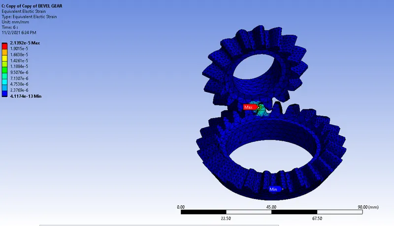
The bevel gear of elastic strain has to be max. at 2.1392e-5mm and min at 4.1174e-13mm as shown below.
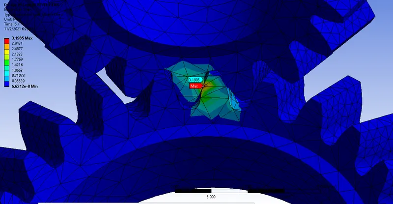
The maximum stress is due to the max. 3.1985MPa and min. of 6.6212e-8MPa as shown below.
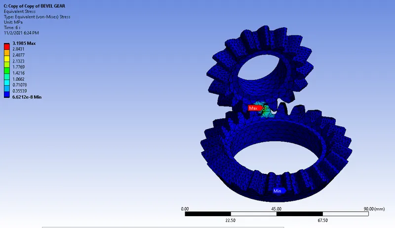
Then select the max. 3.1985MPa prob for these shown below.
Results
The results have been tabulated below as shown below.
| Total Deformation | Elastic strain | Stress | No. of nodes | No. of elements | Computational time | |
| Case 1 | 47.873mm | 1.9361e-5 | 3.431MPa | 41581 | 25257 | Low |
| Case 2 | 47.873mm | 3.6053e-5 | 5.5543MPa | 42595 | 25858 | Medium |
| Case 3 | 47.873mm | 2.1392e-5 | 3.1985MPa | 44232 | 26855 | High |
Conclusion
- By analyzing the all following results the total deformation has constant of 47.873mm for all cases.
- The percentage of the elastic strain will be some more equal in all cases.
- Equivalent stress changes according to the elemental size changes. The elements size will decrease the accuracy in the simulation of results.
- The elemental size will depend upon a lot of factors of computational time, the accuracy of results and the type of application to be used, and so on.
- Then select the proper mesh size to consider the above mention factors.