Assignment 7-Side Pole Crash Simulation Challenge
Aim- To perform the side body crash given BIW mesh model of Neon car to get proper results.
Objectives - The following perform the frantal crash analysis has done below shown.
1) Import the BIW model in to GUI.
2) First do the mass balancing in the hypercrash and export the file.
3) Import the file of the 0000.rad in to the hypermesh.
4) Check the unit system, create interface, penitration check,Regid wall , unused, empty.
5) Assign the parameters values to create interface of standerd parameters for crash.
6) Assign the parameters for the initial velocity as per the FMVSS standerds, time step,run time,Intrusion, section,TH for the peak velocity.
7) Simulate the component and get the results and make conclusions.
Introduction
What is the side pole crash?
This final rule incorporates a dynamic pole test into Federal Motor Vehicle Safety Standard (FMVSS) No. 214, “Side impact protection.” To meet the test, vehicle manufacturers will need to assure head and improved chest protection in side crashes. It will lead to the installation of new technologies, such as side curtain air bags and torso side air bags, which are capable of improving head and thorax protection to occupants of vehicles that crash into poles and trees and vehicles that are laterally struck by a higher-riding vehicle.
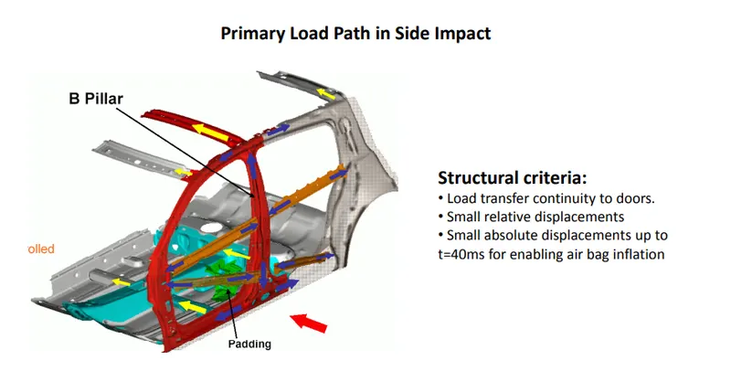
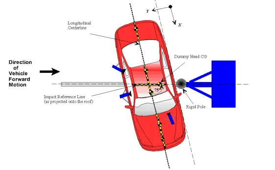
The side body crash test has been of the takes place in the laboratories. For all this kind of the crash tests has been tested and the getting the plot the results after done with the crash test. With the maintening the proper boundary conditions with the all type of the
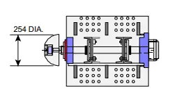
This laboratory procedure is to be followed while conducting compliance tests to the requirements of S9 of FMVSS No. 214, “Vehicle to pole requirements.” Each vehicle shall be tested by impacting it into a fixed, rigid pole 254 mm (10 inches) in diameter, at any speed up to and including 32 km/h (20 mph). These requirements apply to passenger cars, multipurpose passenger vehicles, trucks and buses with a gross vehicle weight rating (GVWR) of 4,536 kilograms (10,000 lb) or less, except for walk-in vans, motor homes, tow trucks, dump trucks, ambulances and other emergency rescue/medical vehicles (including vehicles withy fire-fighting equipment), vehicles equipped with wheelchair lifts, vehicles with a raised roof or altered roof and vehicles which have no doors, or exclusively have doors that are designed to be easily attached or removed so that the vehicle can be operated without doors.
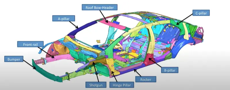
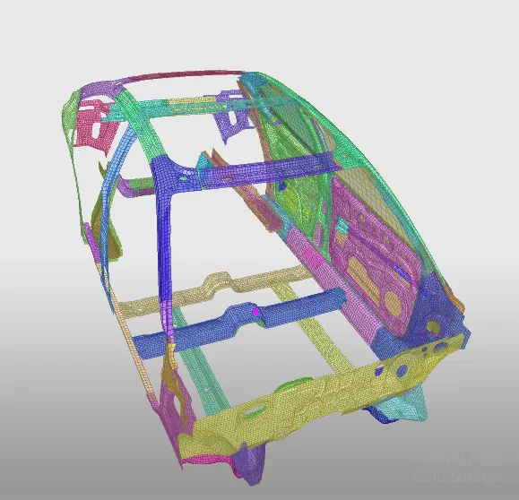
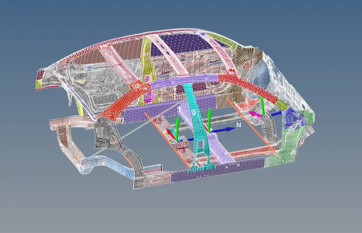
The important features of the BIW is shown in the below.
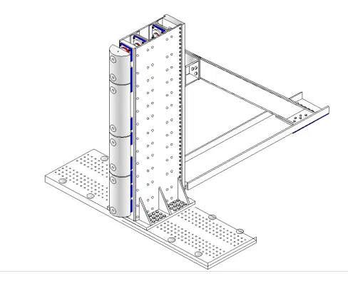
The below shown the test has been carried with under the load case set up of the pole dia should be 214mm the all in the laboratory condition.
TEST EXECUTION
In laboratory conditions needs to follow these following steps.
A. RECORD VEHICLE SPECIFICATIONS
Using the Monroney sticker label, tire placard, Part 567 certification label and tire sidewalls collect and record vehicle specifications, tire data, standard and optional equipment originally installed on the vehicle.
B. PREPARE THE VEHICLE FOR THE TEST
Determine the weight and attitude of the test vehicle in its “as delivered” condition. The “as delivered” condition is the vehicle as received at the test site, with 100 percent of all fluid capacities and all tires inflated to the manufacturer’s specifications listed on the vehicle’s tire placard.
C. POSITION THE DUMMY IN THE TEST VEHICLE
Place a Part 572 Subpart U or V test dummy configured in accordance with TP-P572U or TPP572V calibration test procedure in the driver or front outboard passenger position on the struck side of the test vehicle. The test dummy shall soak for 24 hours in an environment that is maintained between 18.9°C and 25.5°C and at any relative humidity from 10% to 70% prior to being placed in the test vehicle. The test dummy is positioned in the test vehicle the morning of the test. The NHTSA COTR will specify dummy type and which side of the test vehicle to impact.
D. DETERMINE THE “AS TESTED” WEIGHT AND ATTITUDE Determine the actual weight and attitude of the test vehicle in its “as tested” condition. The “as tested” condition represents the actual test weight and attitude of the test vehicle prior to impact.It includes the weight of all instrumentation, onboard cameras, lighting equipment, test dummyand umbilical cords, etc. The weight of the test vehicle in the “as tested” condition must lie within the required weight range. The attitude of the test vehicle in the “as tested” condition must lie between the “as delivered” attitude and “fully loaded” attitude, inclusive. Record the weight of the ballast added to the test vehicle and any vehicle parts removed from the test vehicle to achieve the “as tested” condition.
E. TAKE DUMMY MEASUREMENTS
After positioning the dummy in the front outboard seat, measure its pelvic angle and proximity to the vehicle’s interior. (See Check Sheet No.12)
F. APPLY CHALK PAINT COLOR TO THE TEST DUMMY
To document the dummy’s interaction with the vehicle’s headliner, side airbags and interior door panel during the impact event, apply chalk paint to the head, face, hip and shoulder of the test dummy. (See Check Sheet No. 13)
G. TAKE PRETEST PHOTOGRAPHS AND VIDEO
Take photographs and video of the test vehicle in its as-tested condition.
H. TEST EXECUTION
Doors and hatches are closed shut. Automatic transmissions are placed in neutral. Manual transmissions are placed in 2nd gear. The parking brake is fully engaged. The ignition is in the power “On” position. Sunroofs are placed in the closed position. If the vehicle has a convertible top, place it in the closed passenger compartment configuration.
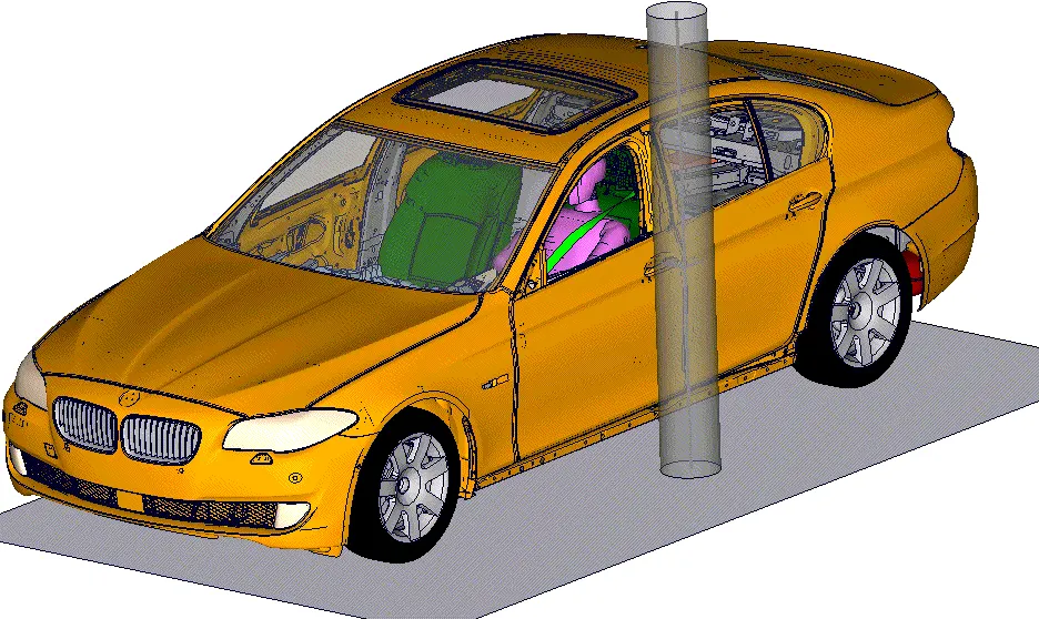
The below image shows the when the car has been crashed with the pole. The technology has been introduced airbags in to the car has been protect from the side crash.
Procedure
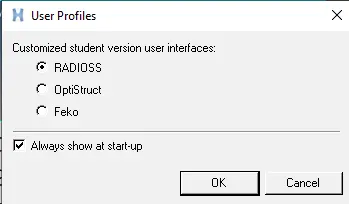
Open the hypermesh and select the profile as radioss.
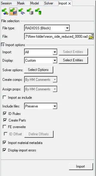
Import the starter file from the solver deck as shown in below and import in to GUI.
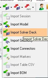
From the solver deck import the model of 0000.rad.
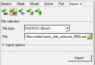
The process flow should be start from the mass balancing.
Mass balancing
For the mass balancing will done by using the hypercrash.
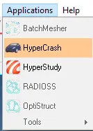
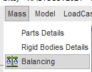
When it was open the by using the mass balancing as shown in below.
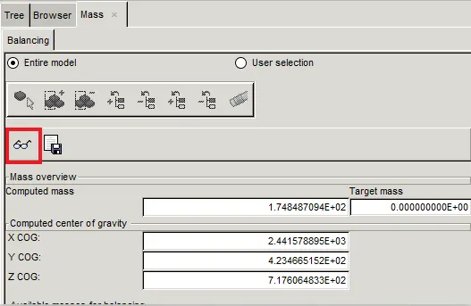
Select the COG point and it will show the COG point.
The current mass is to be 166 so as per the given statement make it 700.
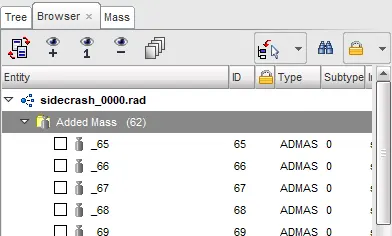
The added mass has to be done while going the added mass and crate new.
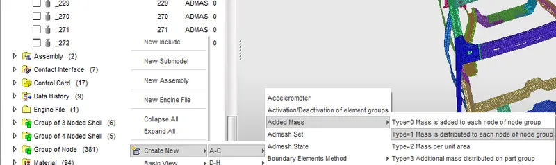
The mass can be added and as type1 with the mass is distributed to each node of the node group.
The added mass is to be the balance is to be the 700 has to be maintain as shown the below.
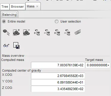
The image as shown in the below shown the COG point and mass has to be balance.
Export the file to import the that file in to Radioss.
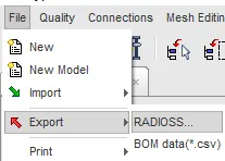
Import mass balancing the file of 0000.rad can import into the GUI.
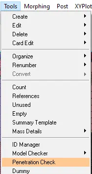
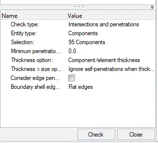
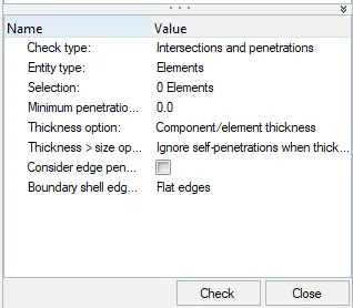
The needs to check the penitration check of the component.
The check has been done by selecting the all 95 components and check then it should be seems to be the 0 as shown in below image .
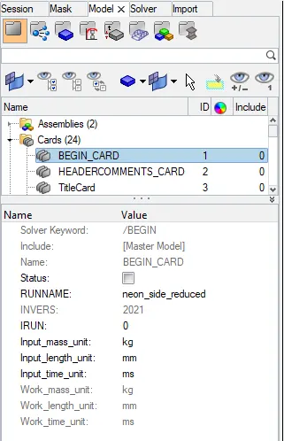
First check the unit systems of the cards and assign the parameters according to that.
Creating interface for the given crash model.
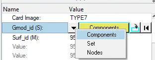
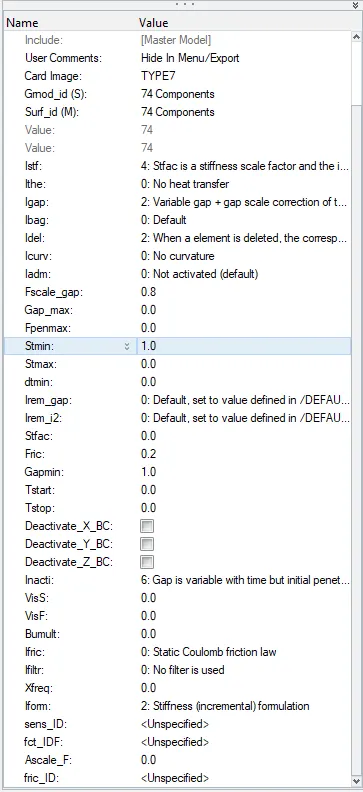
The parametrs can be assign as TYPE7. It is specially used for the most of the crash applictions.
Also select the all components and assign the standerd parameters for the TYPE7.
Create the rigid wall as cylinder and selecting any point in the cylindrical pole has been created press enter.
Assign the distance to be search, friction and diameter in to the pole.
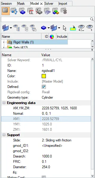
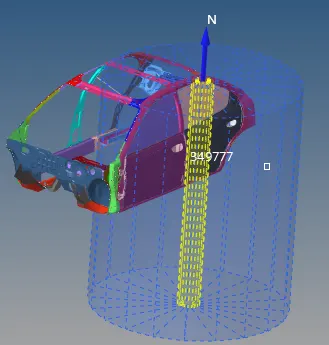
As below shown the created pole for the side crash car model.
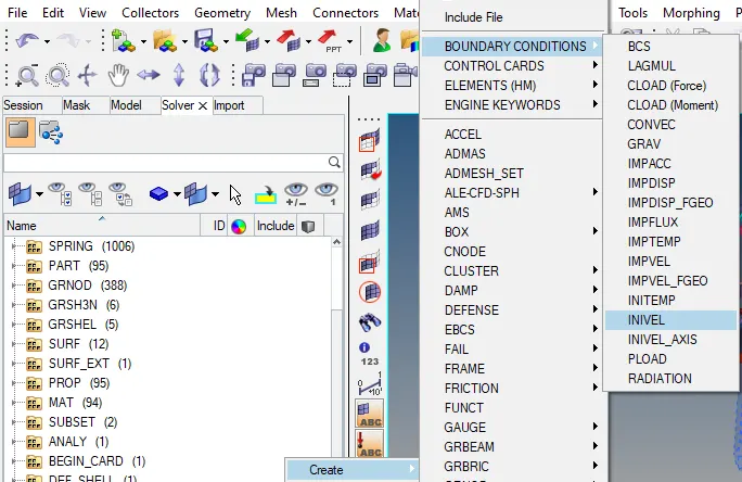
The assignthe parameters for the boundary condition and select the INVEL.
By the FMVSS(Federal Motor Vehicle Safety Standard) standers for the side crash of car. The given standerd veleocity has been given as 32 km/h (20 mph). The 20 mph has been converted into the ms. By converting 8.9408 has assign in to the INVEL of velecity of the component.
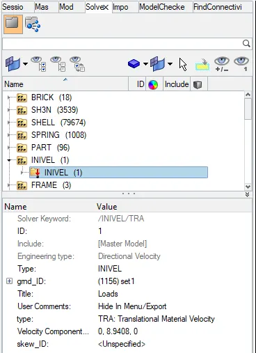
By selecting the gmd ID> create/edit > entity id > Select all nodes > proceed.
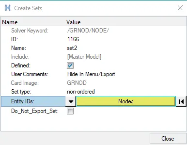
To selection for the all nodes is as shown in below.
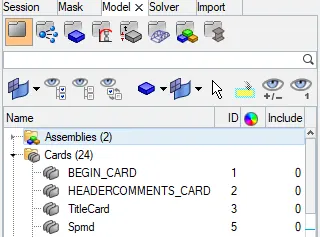
Time step
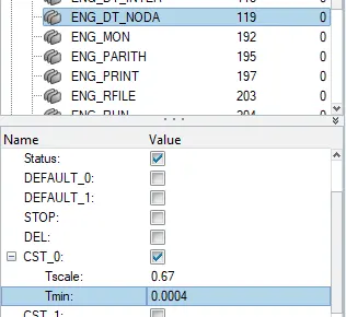
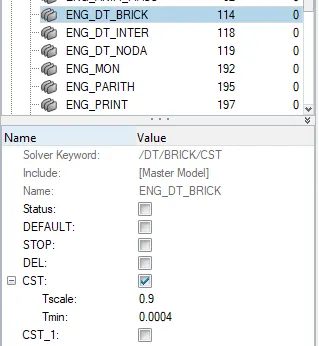
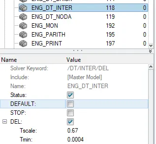
Assign the Tmin value in to the card collector as per the mention in the statement.
Assign the parameters for Tmin and Tscale in to the NODA, BRICK and INTER as per the given statement.
Run
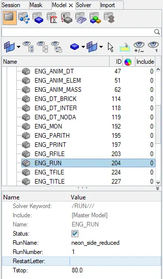
Give the run of Tstop at 80 has been assign into the run collector.
Intrusions
Creating the intrusion springs for the car body in the such a way that 3 intrusion springs is create in the hinge pillar, B- piller and in fuel tank respectively.
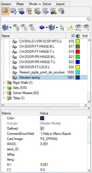
Assign the parameter of spring stiffness will assign. By using the 1D connections the intrusion spring has been created.

The spring2 has been select between the 2 nodes and create.

In model assign the spring property in to it and apply for the 3 intrusion spring as shown in below.
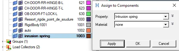
Fram and Sections
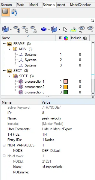
Creating the 3 sections in the 3 regions by creating the frame as the MOV.
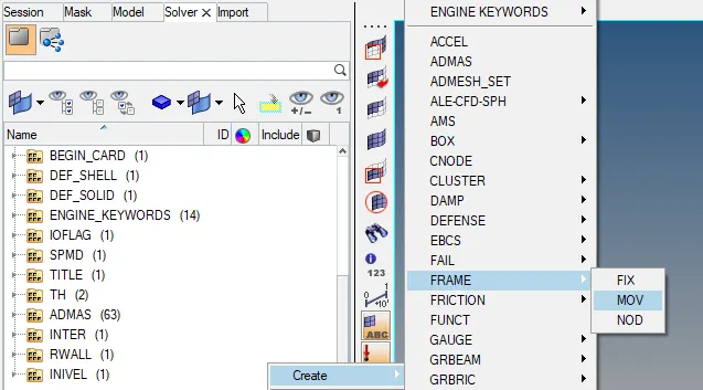
Select the node in such a way that the first node as the center, second node represent the axis to impact and third has been the free direction has to be set.

Similarly all frames can be created. To create the SECT for same frames and create the system and select the system diraction and proced.
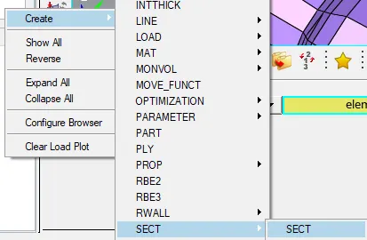
The below shown the select the thickness and other parameters of the delta and alpha.

Below image has shown the frame has been created.
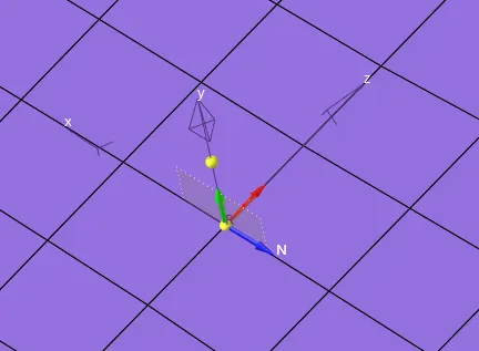
To create the sections, assign the all sets of in the grshell id and
Create- section- sect - select N1,N2,N3
N1- is the center.
N2- As the direction car has moves.
N3- Left side or Right side.
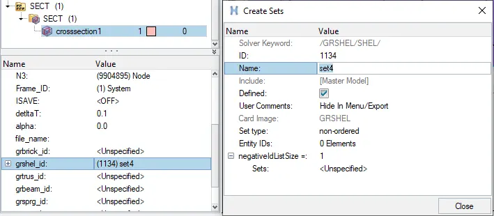
Given Delta= 0.1
Alpha= 0.67
grshell > edit > create > select elements> proceed > close.
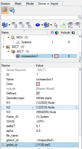
Similarly for 3 frames and sections has been created as shown in the below.
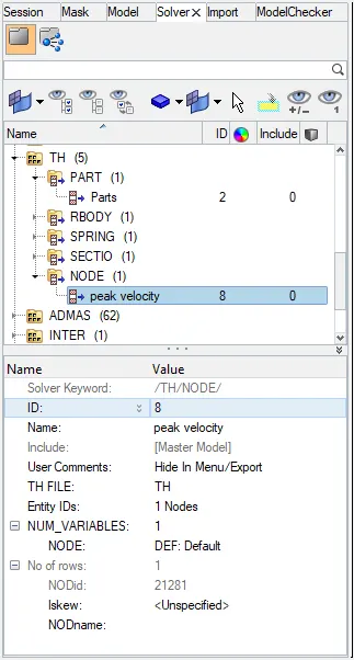
Time Hystory
Assign the TH for the peak velocity by slecting the node as metion in the statement.
After completing the all parameters has assign check for the unused and empty as shown in the tool bar as shown in below.
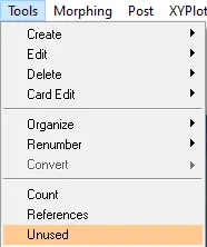
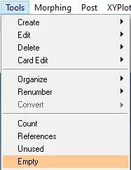
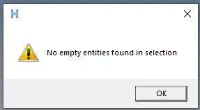
The delete up to it shows the no empty entities in selection and ok.
Modular Checker.
Similarly for the model checker in radioss block
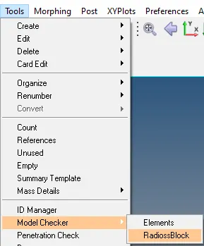
It will shows some error and warnings. The shown error can be solved and warning can be adjested/ neglected.
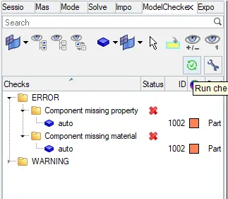
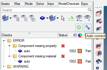
After solve the all the errors ready for the simulation save in the proper file and select the include the connection, select the option is for the _nt 4

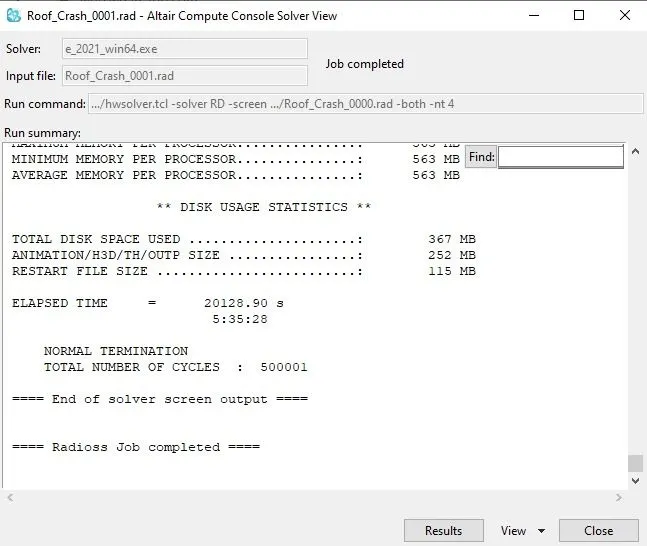
After few hours of time the simulation has conpleted and its as shown in below.
After run the simulation get the results for the side body crash files has been saved. Open the run file of 0001.out as shown in below.
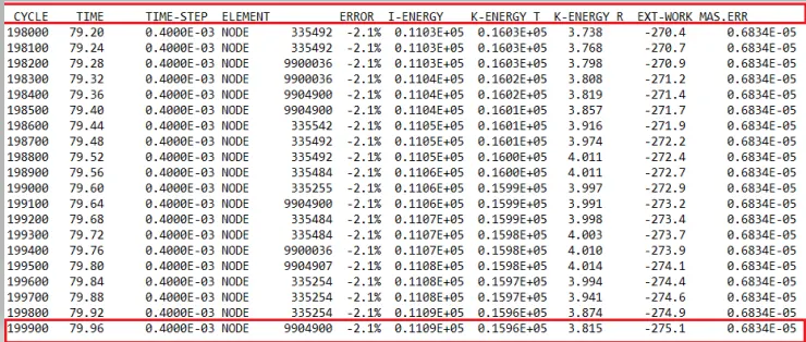
The energy error has been -2.1% has acceptable because there is range of the energy error has been accept up to the range of -15% to the +5.
The given results got from the simulation.
Cycle time - 199900
Energy error - -2.1%
Mass error - 0.6e-5%
Elapsed time = 8086.59 s
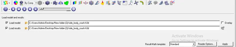
Run for the h3d file in to the GUI by selecting the hyperview and apply for the run file.
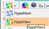
The select the file of h3d and apply in to the GUI and play for the animation.
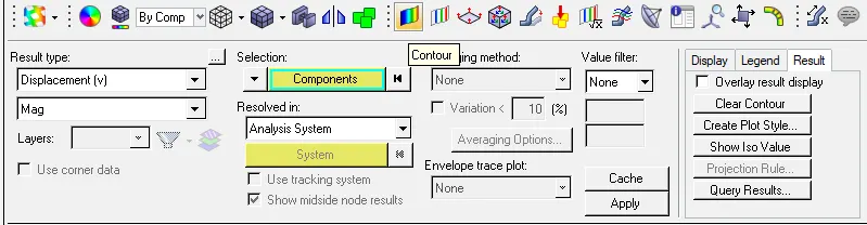
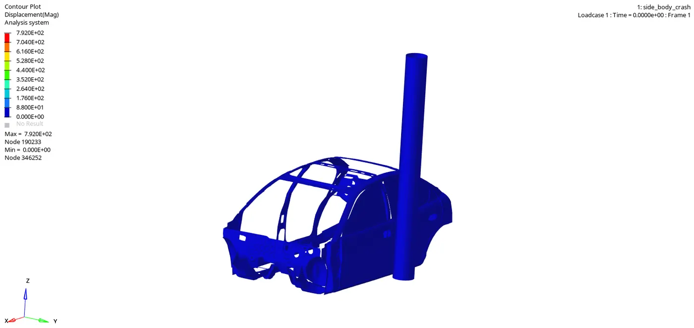
After apply select the contour for the component and the displacement of the car body with side crashed with the side pole animation will be reflect on screen.
The below shown the while running the h3d file the animation for the displacement of car body and the deformation in the body change when its hit by the pole due to the inertial force and mass of the component will be acts like the deformation in the body.
From the A piller got more deformation by visulising animation and its shows the results for the component.
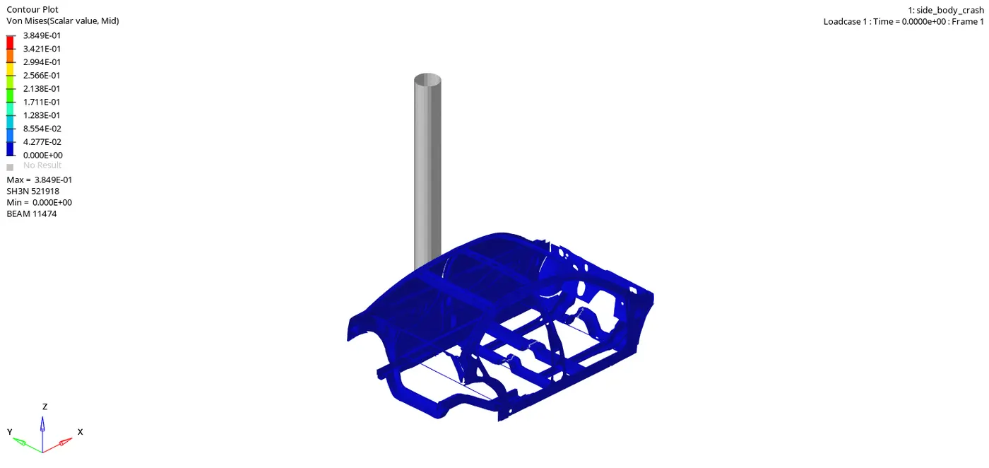
The below shown tyhe von mises for the side crash body applying the direct and indirect stresses with the different type of the forces are acts and its shown in below.
These following results plot the graphs in the hypergraph 2D as shown in below.
The import the T01 and selecting the globle variables of the selecting differnt energies and apply.

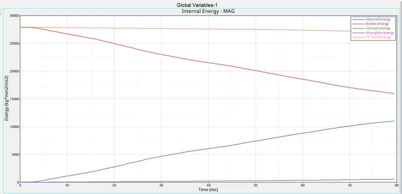
The below shown the global variables of the different energies can be plotted. takes place and its shown in below graph.
- The total energy has to be of resultant of all energies are to become the total energy and its shows the some energy error of 0.6834e5 was shoing but it has been acceptable.
- The kinetic energy has been decreasing from the higher energy to lower energy as shown in below figure. It means when the body will hit with the side pole the kinetic energy of the car has been decreases 0.1596e5 as per the record.
- The internal energy has been depends upoun the deformation for the car body. In graph there is internal energy has been starts from the origine, means no deformation at starting. After some time when the car body hit with the pole the body will get deformation.
- The hourglass energy has been not effects the because of the standerd parameters of fully intigrated nodes has been assigned in the parameters. It has been calculated 5% of the internal energy has been trated as the hourglass energy.
- The contact energy has been generated due to contact between the car body within the self contact.
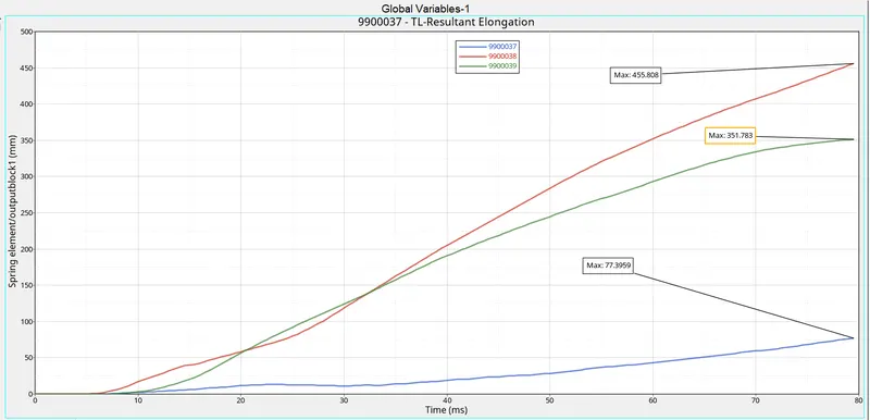
The below shown the resultants springs for the elongation for introducing for 3 springs. The given below shown in the figure there is the resultant eleongation in the springs in 3 of springs as shown in below.
- The intrusion springs are more important parameters to check the humans seafty conditions. In this side crash test has been introducing the 3 intrusion springs in A-piller, B-piller and fuel tank. The introducing the 3 elongation springs in to different region is to determine the car hits with the side impactor to know the various region how intrusion will get affected.
- For this case there is the more intrusion will takes place in the B-piller is about the 455.808. For the fuel tank has been intrusion of 351.783 and for A piller is of having the intrusion of 77.39 as shown in below.
- By observing the graph the intrusion will more in B piller because of the the side inpact will hit the B- piller. The capacity to resisting or elongation of spring should gives the more in graph compere to the other intrusion spring of A-piller and in fuel tank.
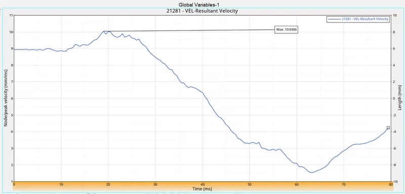
- In below shown image is for the given standerd velocity as per the FMVSS-214 is standard for the side pole impact test speed for what we are assigned.
- As per the FMVSS-214 is the given the 20mph. Convert into the milisec. is the 8.9408ms has been assigned.But it was showing of the 10.0366 the resultant velocity has been increases. It is due to the inertial force and mass factor.
- Gradually it is decreases and the velocity has been decreases gradually.
- Due to the limitation of nodes the B-piller has showing the max deflection in real case the car having all assembly component will give the more stiffer when th crashes for the side body impact because there is front and rare axiels are gives to resist the intrusions kind of things.
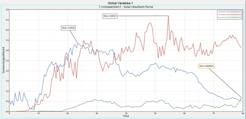
The toatal resultant forces of the 3 sections has been shown in the below.
The section force in the model will gives the cross member of the B-piller attached c/s, passanger seat attached c/s and A- piller attached c/s will be help to transfer the force from the one end to other end. Also will results in to arising the deformation in the body will be created.
For this case below shown they will transfer the section force from the one end to other end. The section force of the model should effected in actual case in the passenger seat. This case affects more in B-piller attached c/s, passenger seat attached c/s and A- piller attached c/s has to be gives the 4.69347, 3.33534 and 0.684825 respectively as shown the below graph.
Learning outcomes
- How to do case set up for side crash test.
- how to set the rigid wall interface and set the kinematic condition.
- how the sectional force is created.
- How the make mass balancing for the component.
- how distribute the forces with the component during crash.
- How to debugging the errors in order to get the results.
- how to take the peak velocity for the car components.
Results
By doing this side pole car test will gives to understanding by simulating and running the h3d file of animation. Also have the proper graphs we can analyse the basic things to be understand. The more to know with this happen only set with the proper load conditions and also standerd parameters assigning with side body crash test will be gives result in to how side body impact will happen, at what are the regions will be gets effected. Also will be having the breef idea about the intrusion force will effected with the car body.
To know the more information about is for the FMVSS-214 standerd for U.S the given file.
Link for the FMVSS - file:///C:/Users/Admin/Downloads/TP214P-01.pdf