Week 2 Railwheel and Track
Aim- To perform the static structural analysis for the given model.
Objectives-
To perform the static analysis of rail wheel on track and compare with cases of when baring load changes.
Procedure- open with the Ansys workbench and the Below shown toolbox with GUI is given.
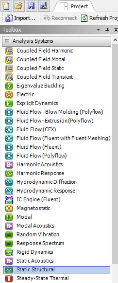
Double click on the static structural and it will show the project schematic as shown below.

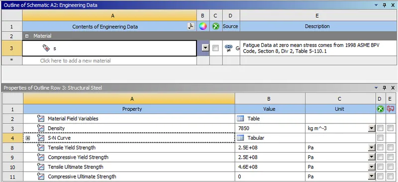
Select the material as the structural steel as shown and assign the proper parameters to it.
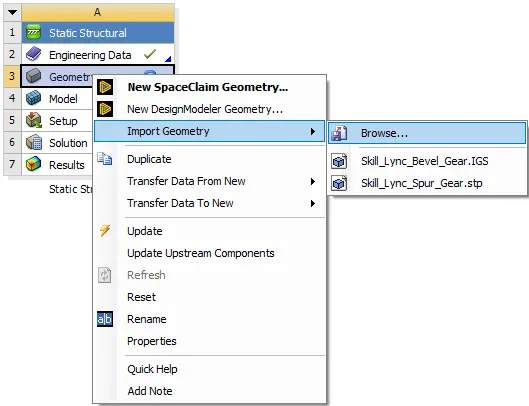
Import the geometry by browsing and selecting the given model.
After importing the model as shown below.
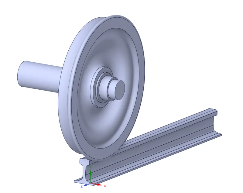
For the model, the material has been selected as the structural steel and select the contact rename based on definition.
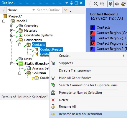
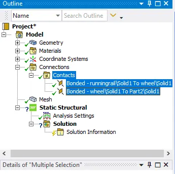
Select the contact as the bounded and assign the proper selecting the surfaces of the model shown below.
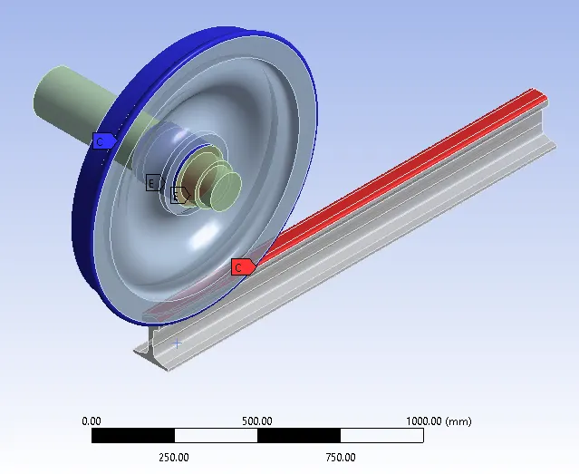
On first contact select the wheel outer surface and the upper surface of the track wheel as shown below.
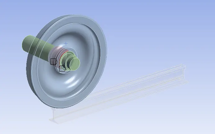
On the second contact select, the bearing shaft surface and inner dia of the wheel have been selected as shown below.
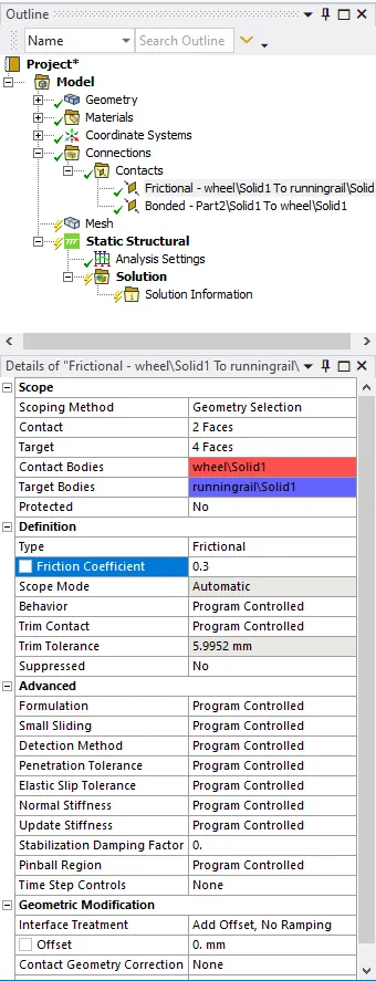
Select the proper contact bodies and target bodies have been selected. Also, select the definition type as frictional and friction co-efficient as the 0.3.
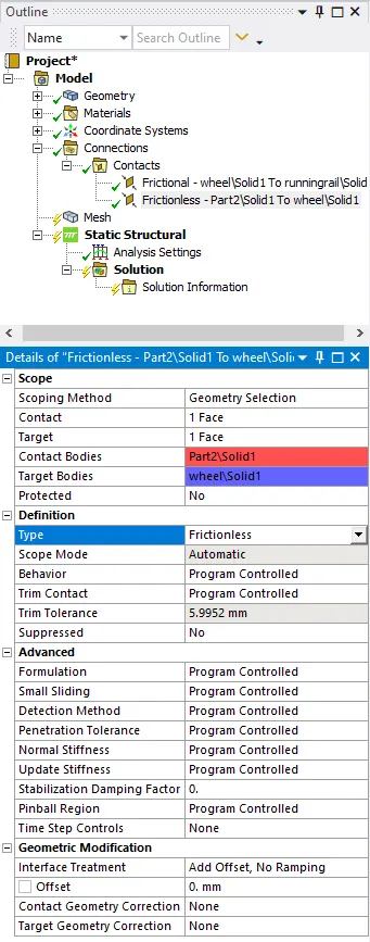
Select the joints to create the connections.
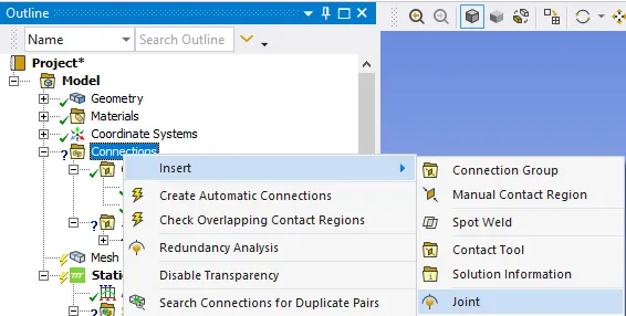
There are three types of joints that can be created.
Select the joints 1 for the fixed rail track and with the proper direction of the y-axis as shown below.
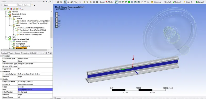
Then select joints 2 for the translational for the wheel center baring shaft with the proper direction of the track will be selected as shown below.
with the selecting the scoop of the select the shaft surface select te body as shown below.
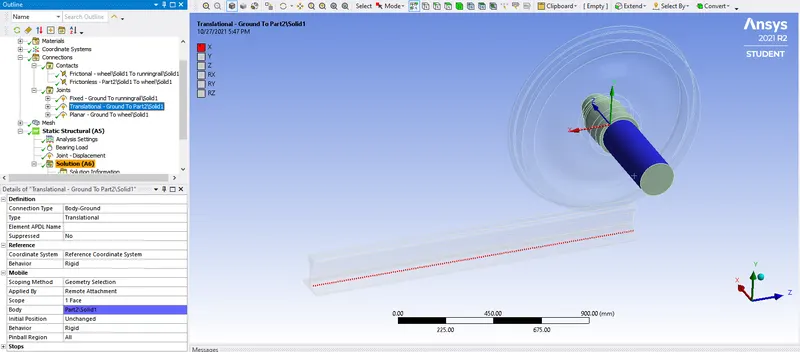
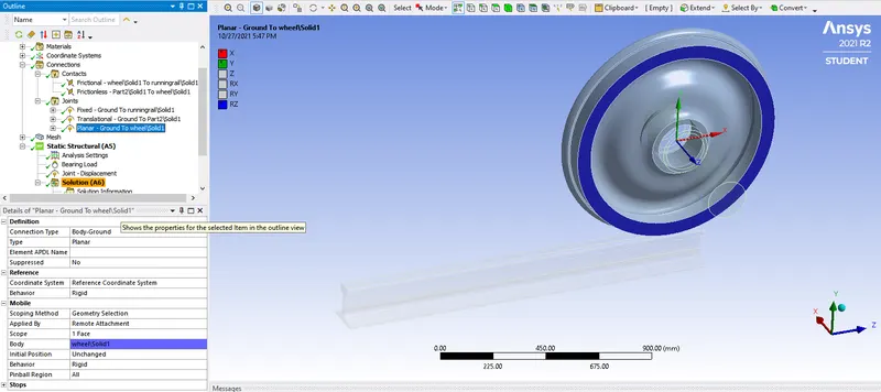
For the third joint select the wheel as the center with proper directions can be selected as shown below.
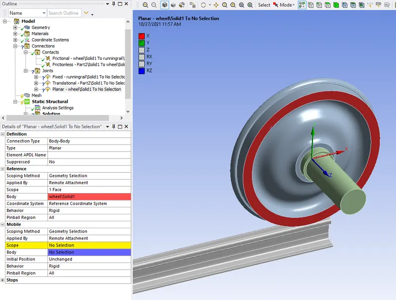
Select the connectiontype as the body- ground also select the scope and body of the wheel as shown below.
Select the proper mesh size IS 50mm and do the mesh as shown below.
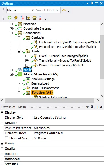
Also, select the mesh make the sizing as shown below.
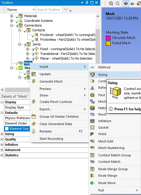
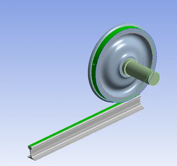
Select the 35mm mesh sizing that has been shown below of the sizing surfaces as shown below.
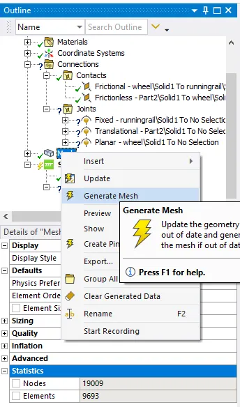
Select the generated mesh it will take some time to complete.
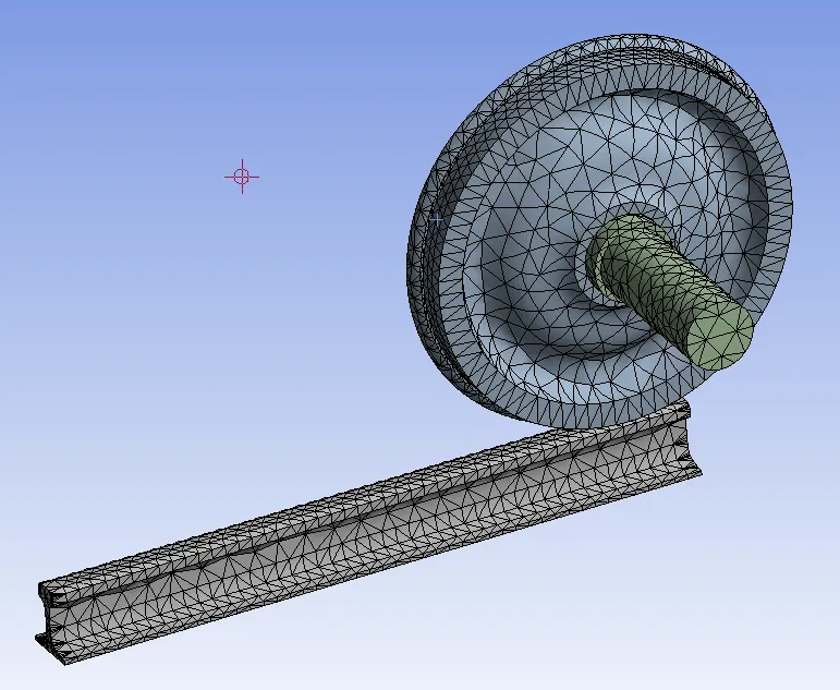
The meshed model of the rail wheel track is shown below.
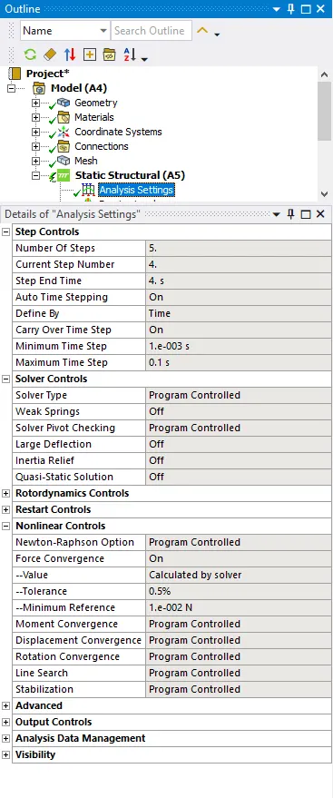
The set the static structure of analysis settings as shown below.
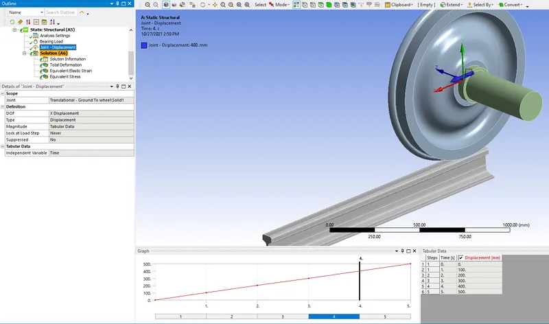
Introduce the joints in the static structural has been created. Then select the DOF as the X displacement as shown below.
Assign the proper graph value for the joint.
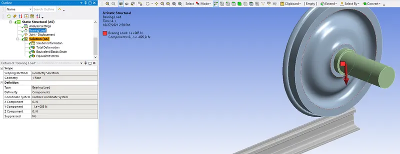
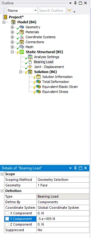
Assign the bending load of the 100000N and geometry also has been selected as shown below.
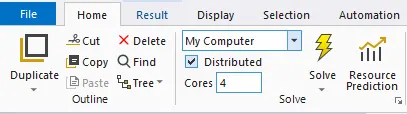
On the home page, core 4 has been selected as below shown.
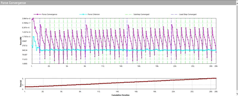
The force convergence graph has been created as shown below.
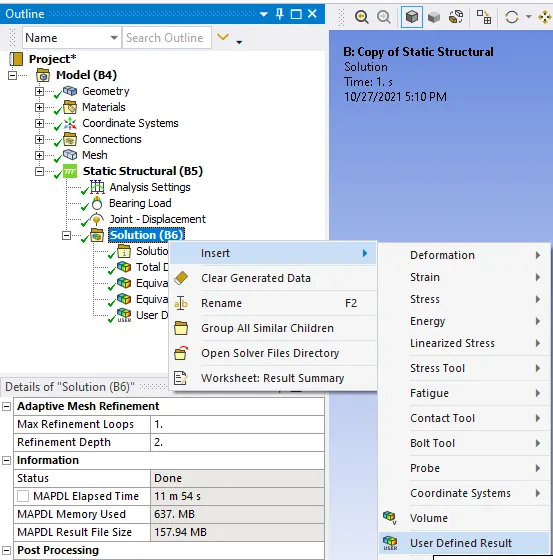
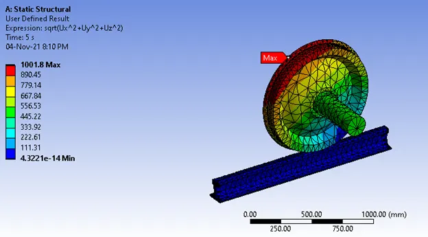
Similarly for the solution insert the user-defined results as shown below.

Assign the geometry select all, add the expression of the as below shown.
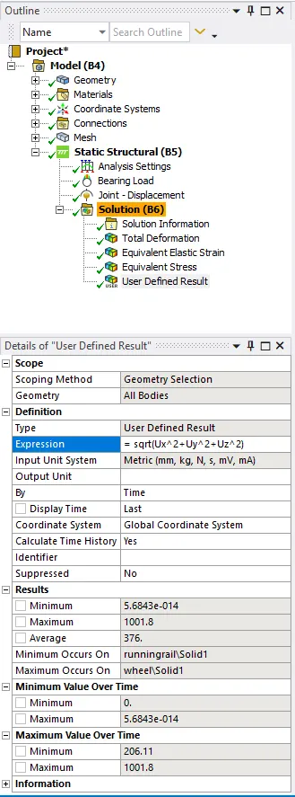
Also mention in the user-defined result.
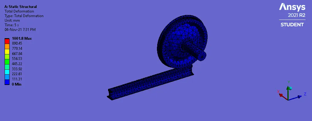
The static structure of the model is in the form of a total deformation of 1001.8mm.
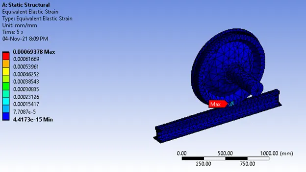
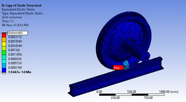
The elastic structure of max. of 0.00069378mm and min. of 4.4173e-15mm is shown below.
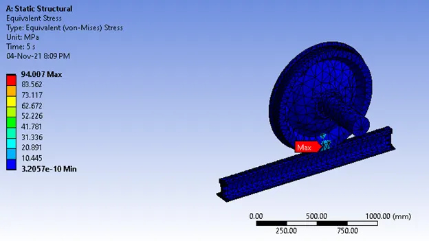
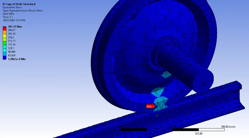
The static structure of the equivalent stress 94.007MPa and min of 3.2057e-10Mpa is shown below.
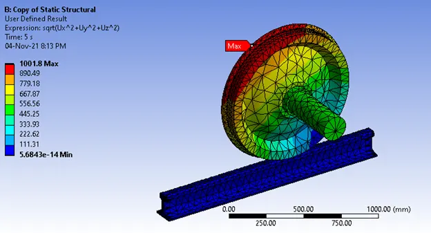
The user-defined result is of max. 1001.8 as shown below.
Case 2
Similarly in the second case has the same procedure continue up to the user-defined results.
Only has to assign the bending load of the 500000N as shown below
The force convergence graph has been created as shown below.
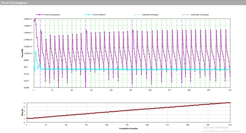
The total deformation is of the changing the load of 500000N its shows 1001.8 as shown below.
The elastic structure of max. of 0.00024559mm and min. of 4.4173e-15mm is shown below.
The static structure of the equivalent stress 387.31MPa and min of 1.2867e-9Mpa is shown below.
The user-defined results have been shown the max. of 1001.8 and min of 6.684e-14 as shown below.
Results
The below-shown results have been tabulated.
| Total deformation | Elastic strain | Stress | User-defined result | Load in N | |
| Case 1 | 1001.8mm. | 0.00069378mm | 94.007MPa | 1001.8mm | 100000 N |
| Case 2 | 1001.8mm | 0.00024559mm | 387.31MPa | 1001.8mm | 500000 N |
Conclusion
1. Total Deformation (Max) comparatively same in both cases
2. Values of Equivalent Elastic Strain (Max)is higher in Case 2
3. Values of Equivalent Stress (Max) is very high inCase 2
We have analyzed this project. and we can c early see that there is an abrupt change in values of Stress and Strain when the load value is changed from 10e04 N to 50e04. There is no significant change in Total Deformation.
Google Link
https://drive.google.com/file/d/1g1FmhCiGAuBVpEdCQx0sumKG6JqRZY5r/view?usp=sharing