Week 4- Rolling operation
Aim- To perform the static structural analysis of rolling operation.
Objective
The simulation of the rolling operation on a workpiece made of copper.
Increase the length of the workpiece by 60mm and decrease its size on both sides by 8mm.
Run the simulation for 14 steps and you can give small but random values( similar to the ones mentioned in the video) for the displacement.
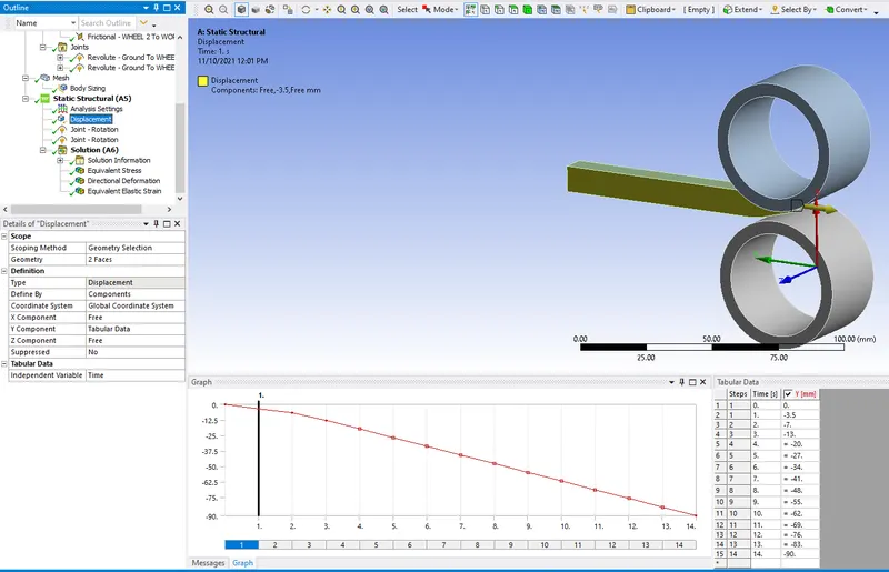
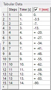
Ensure that the edge of the workpiece is displaced by 90mm.
Introduction
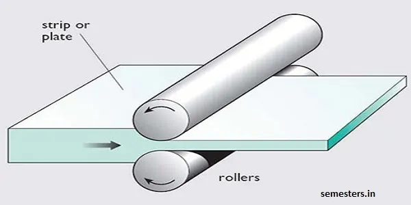
Rolling is defined as a process to form metals where the metal strip is pressed by two or multiple rollers, thus the uniform thickness is formed. To do this, the temperature is essential. There are two types of processes.
Rolling is the most widely used method of shaping metals and is particularly important in the manufacture of steel for use in construction and other industries. Rolling may be done while the steel is hot (hot-rolling) or cold (cold-rolling).
Types Of Rolling
The types of the rolling process can be classified into the following ways-
- Thread/Gear Rolling
- Shape Rolling
- Ring Rolling
- Tube Piercing
- Transverse Rolling/Roll Forging
- Skew Rolling
- Roll Bending
- Flat Rolling
- Controlled Rolling
- By rolling, uniform dimensions of the components can be obtained.
- It uses the same tool in the sense, the same rollers are responsible for the production of various components.
- Close tolerance is possible for the components in the rolling.
- high-speed production takes place in the rolling.
Procedure- To start the simulation by opening with the Ansys workbench.
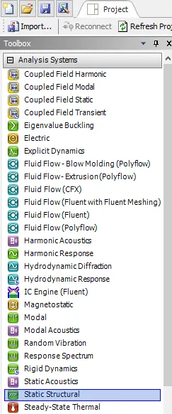
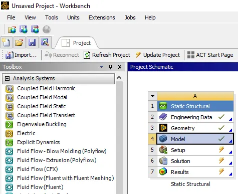
Select the static structure from the toolbox as shown below shown.
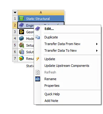
In static structural select to assign the material property in engineering data.
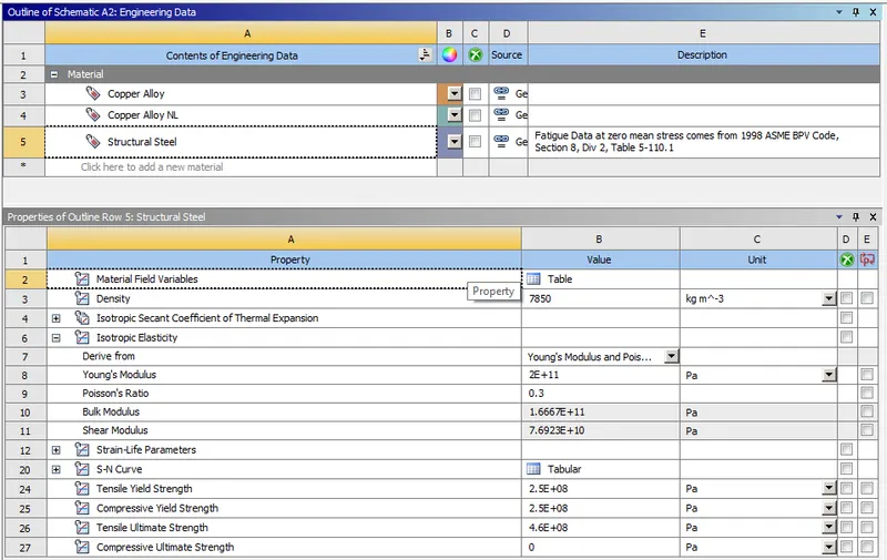
Selecting the material property as the copper alloy and structural steel as shown below.
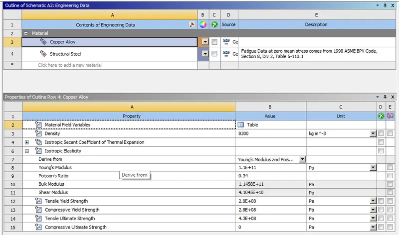
Update the engineering data as shown below.
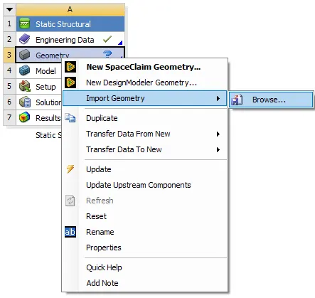
Also import the geometry from the browse with the updated geometry.
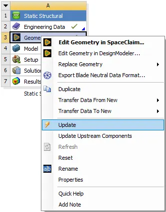
After updating the geometry double click on the model, its popup with the model window.
Rename the geometry as per the name of wheel 1, wheel 2, and workpiece the renamed the geometry.
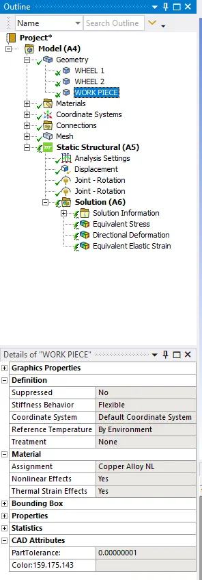
For workpiece assign the material as copper alloy NL as shown below.
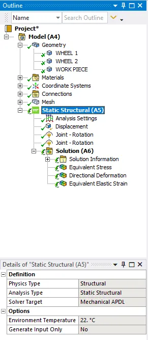
Create the connection and create the contact of the frictional and select the friction coefficient of 0.2 as shown below.
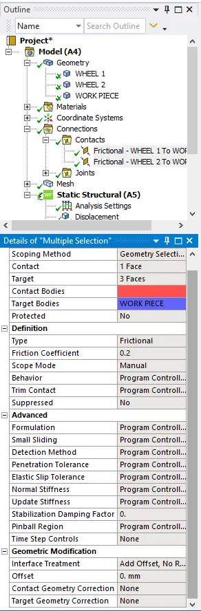
By contact bodies select as the wheel outer surface and target bodies as the workpiece surface as shown below.
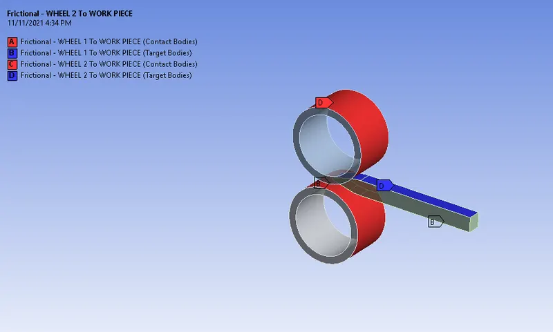
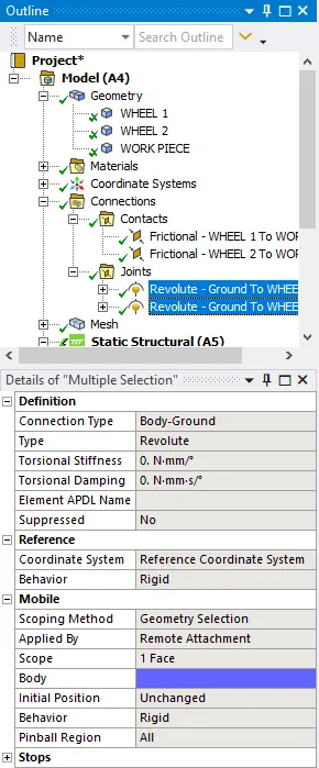
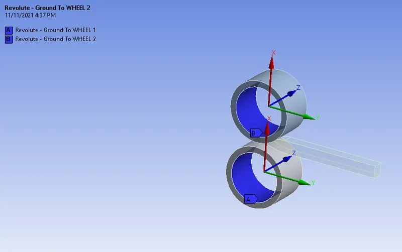
Create the joints as the revolute, select the revolute type as the Body-Ground and inner surface of the wheel has been selected.
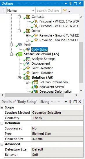
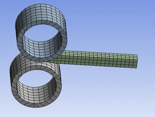
Mesh the given geometry of the 4mm mesh.
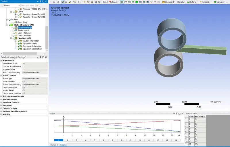
Set the analysis settings of 14 steps, select the steps of 1 to 14 as shown below.
Create the displacement of the two surfaces of the workpiece as shown below.
Also, give the joints for both wheels as the revolute and select the inside circle and also select wheel such as one wheel of clockwise and another will be anticlockwise.
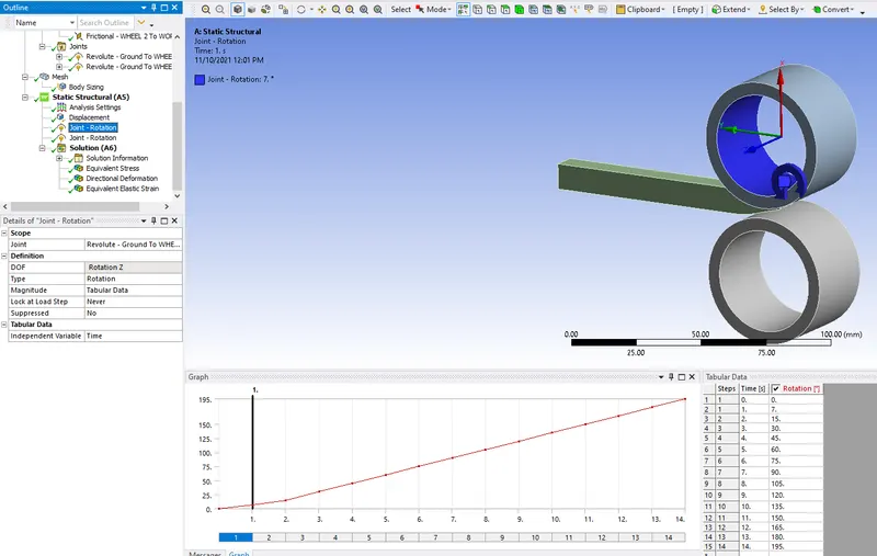

Similarly for the other wheel also have the change the sign for the wheel.
The directions are shown below.
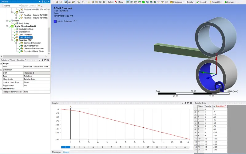
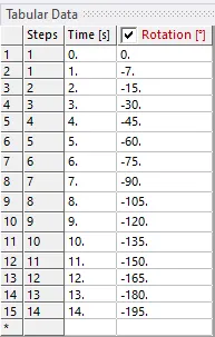
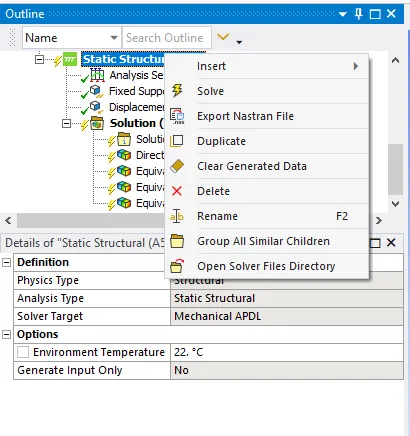
For assigning all parameters solve it as shown below.
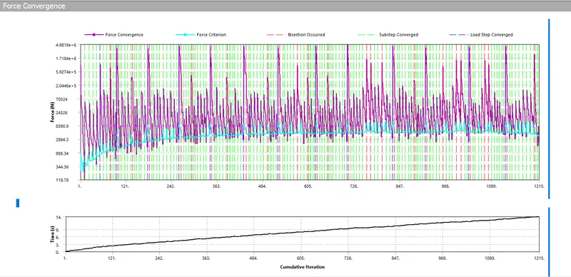
The below shown the graph for the force convergence is shown below.
After solving the plot animation for the stress, plastic strain, directional deformation, force rection, and moment rection as shown below.
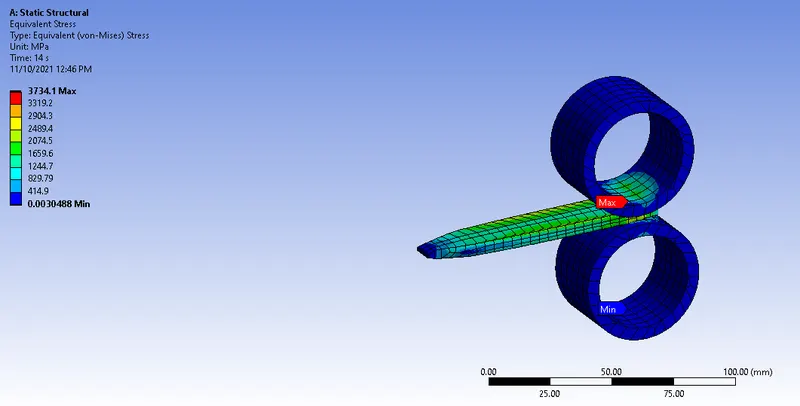
The below shown the equivalent stress is found to 3734.1MPa as recorded.
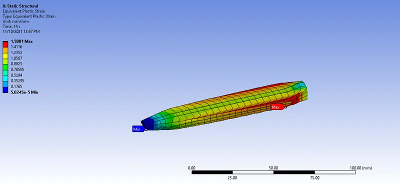
The equivalent plastic strain for the workpiece has been found to be 1.5881mm as ma. and the min will be 5.0245e-5 as shown below.
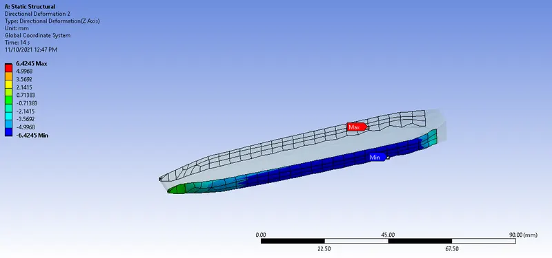
The directional deformation in the Z direction has been recorded as max. of 6.4245mm and min as the -6.4245mm as shown below.
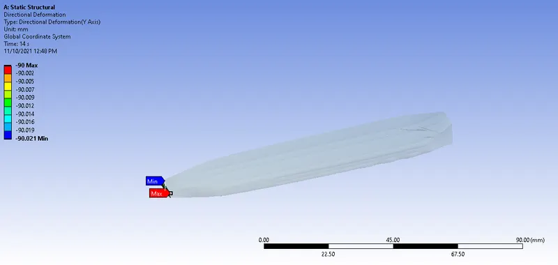
The directional deformation in the Y direction has been recorded as max. of -90 mm and min as the -90.021mm as shown below.
As the directional deformation of the static structural is found to be -90mm has been found but the negative sign indicates the direction for the workpiece to move as shown below.
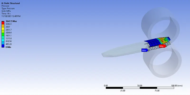
For this rolling operation, the pressure has been found to be 3647.5MPa and as shown below.
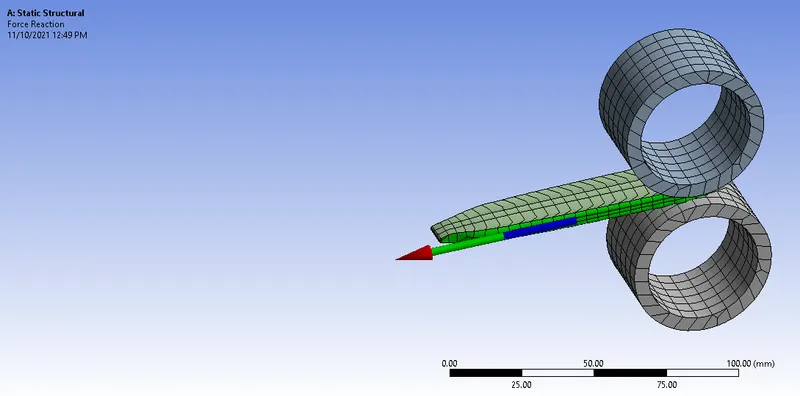
Force reaction
The force reaction has been recorded in the direction of Z as shown below.
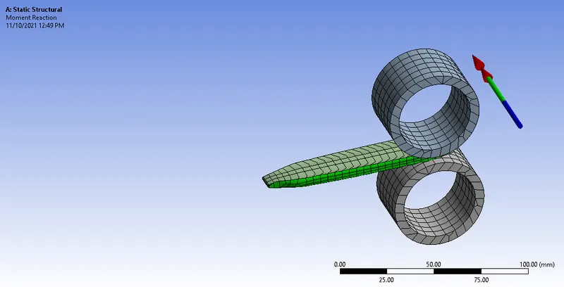
Moment reaction
The force reaction has been recorded in the direction of Y as shown below.
Results
The tabulated all results for Sphere pressing on a plate as shown below.
| Stress | Plastic strain | Directional deformation at (Z-direction) | Directional deformation at (Y-direction) | Pressure | |
| Rolling operation | 3734.1MPa | 1.5881mm | 6.4245 mm | -90mm | 3647.5MPa |
Conclusion
By doing this static structural analysis for rolling operation concluded that.
- The stress and plastic strain for the workpiece rolling are shown the 3734.1MPa and 1.5881mm respectively.
- The directional deformation of the z-direction will be 6.4245mm.
- Proved that the workpiece has displaced by 90mm in the y-direction.
- It has been created pressure of 3647.5MPa has been recorded.