Week 4 -Wire Bending Challenge
Aim- To perform the static structural analysis for the given wire bending component.
Objectives
- Use the Copper Alloy (Non-Linear), Aluminium Alloy (Non-Linear), and Magnesium Alloy (Non-Linear) for the wire alone for 3 different cases.
- Find out the Equivalent stress and Equivalent strain on the wire.
- Compare the results.
Introduction
The wire bending involves bending and cutting the wire to form. Our skilled team members and reliable machines can ensure your wire forms are cut with absolute precision. CNC stands for “Computer Numerical Control”. CNC wire bending uses newer equipment than other types of precision wire forming.
Metal bending is a process by which metal can be deformed when applying force to the subject, which causes it to bend at an angle and form the anticipated shape, which often results in it being in a 'V' or a 'U' shape. A press brake is a tool used in order to bend sheet metal and uses a punch and die to do this.
The easiest method is to use square pliers with sufficiently wide jaws. Start by marking down where you want the bend, taking into account a small error as making a corner-like sharp bend into a piece of wire is not easy. Most likely the wire will have a slight curve at the 90-degree angle.
Procedure- To start the simulation by opening with the Ansys workbench.
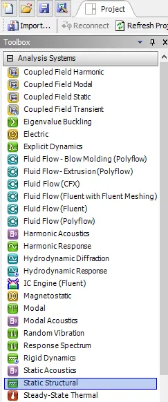
Select the static structure from the toolbox as shown below shown.
In static structural select to assign the material property in engineering data.
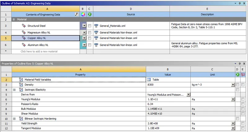
Selecting the material property as the Copper alloy NL for the other case is shown below.
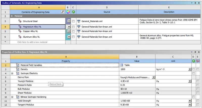
Selecting the material property as the Magnesium alloy NL for the other case as shown below.
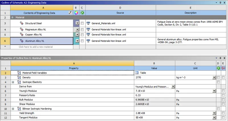
Selecting the material property as the Aluminum alloy NL for the other case as shown below.
Update the engineering data as shown below.
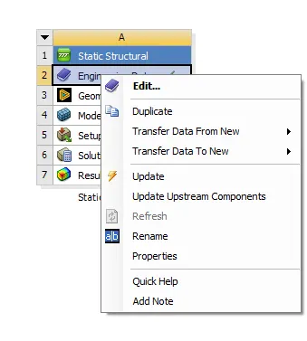
Also import the geometry from the browse with the updated geometry.
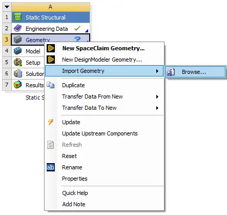
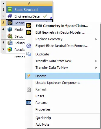
After updating the geometry double click on the model, its popup with the model window.
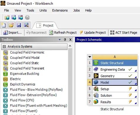
The model can open with the space claim by doing the double click.
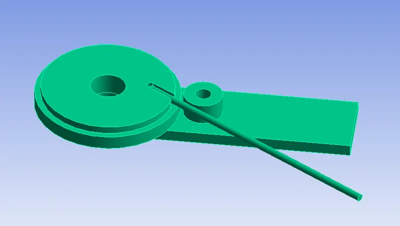
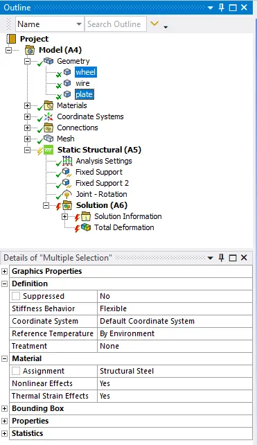
Select the geometry and rename it according to the model have.
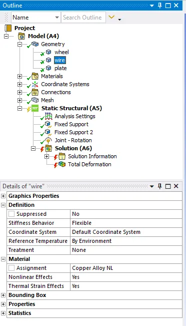
Also, maintain the material as the structural steel for the wheel and plate and for wire select the material as the copper alloy NL as shown below.
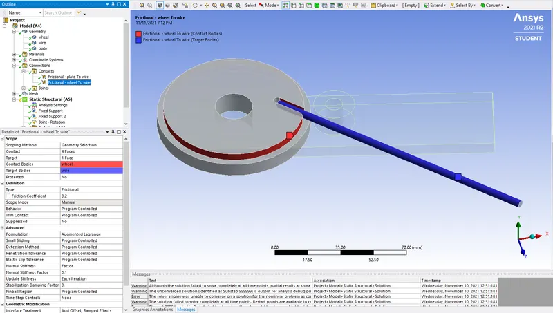
Create the connections for the given model wire and lever with the face that has been selected for the first frictional joint. Add the frictional co-efficient of 0.2 and also select the augmented Lagrange for the formulation.
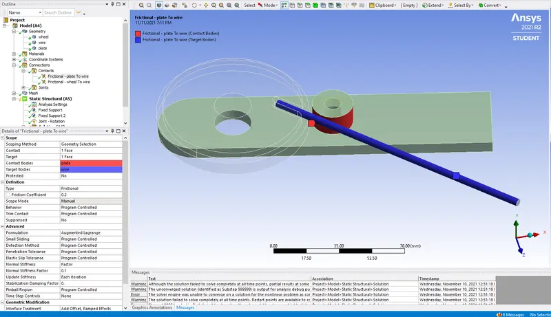
The second frictional joint between the joint wheel and wire is shown below. Add the frictional co-efficient of 0.2 and also select the augmented Lagrange for the formulation.
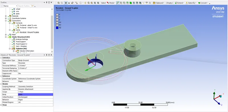
Select the joints to select the connection type will be body to the ground has been selected.
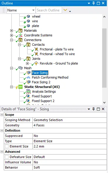
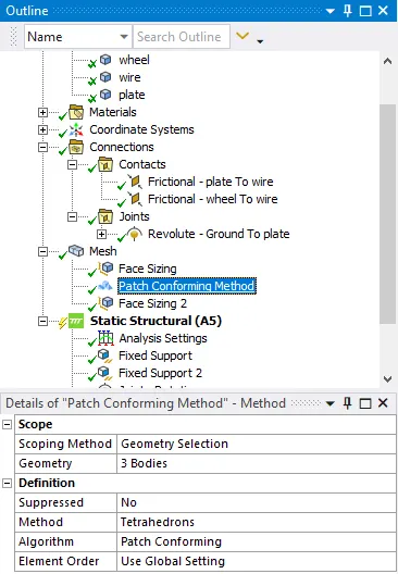
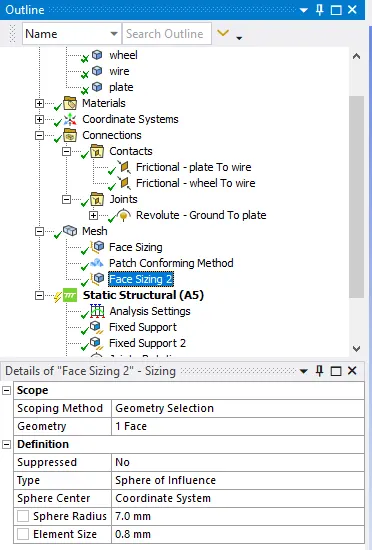
Mesh the component for the face sizing and patch confirming method and face sizing 2 as shown below.
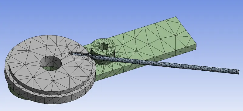
After generating mesh the component looks like below shown.
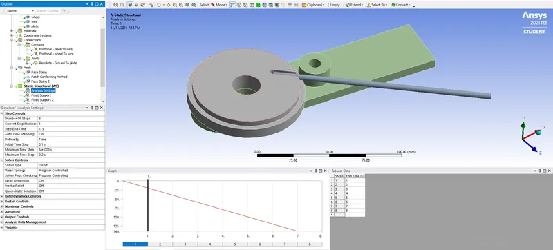
Do the necessary analysis settings for the given component.
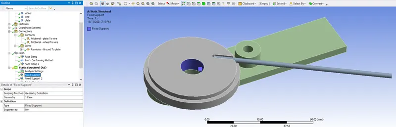
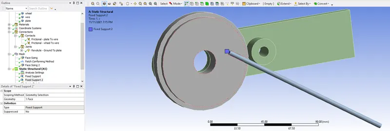
Create the fixed support for the given component as shown below.
Also gives fixed support for the wire also as shown below.
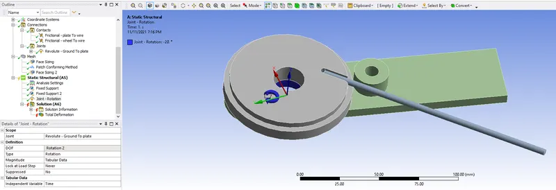
Create the rotational joints for the wheel with the tabular data as shown below.
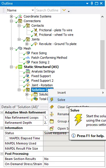
After assigning all parameters solve for the simulation as shown below.
CASE 1
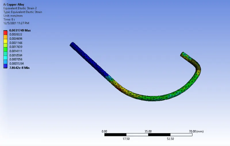
After solving the simulation plot all results as shown below. For copper alloy.
The elastic strain for the given wire will be 0.0031749mm as shown below.
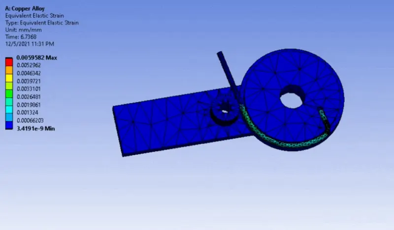
The total elastic strain will be an elastic strain will be max. of 0.0059582mm and min of 3.419e-9mm as shown below.as shown.
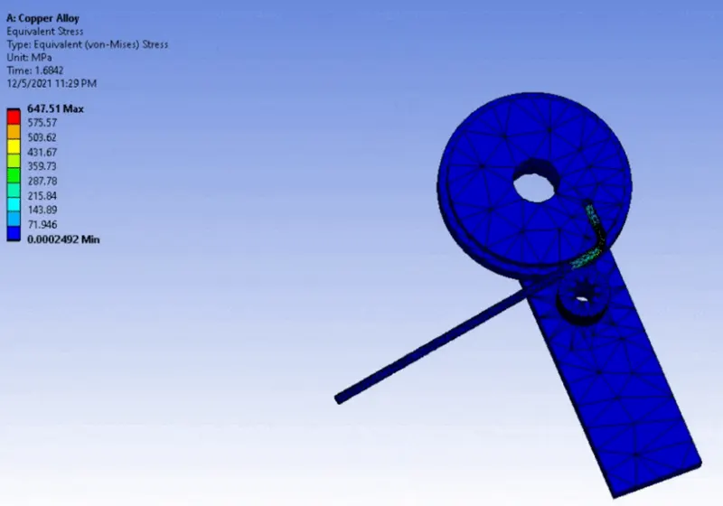
The equivalent stress will be recorded as the max. 647.51MPa as shown below.
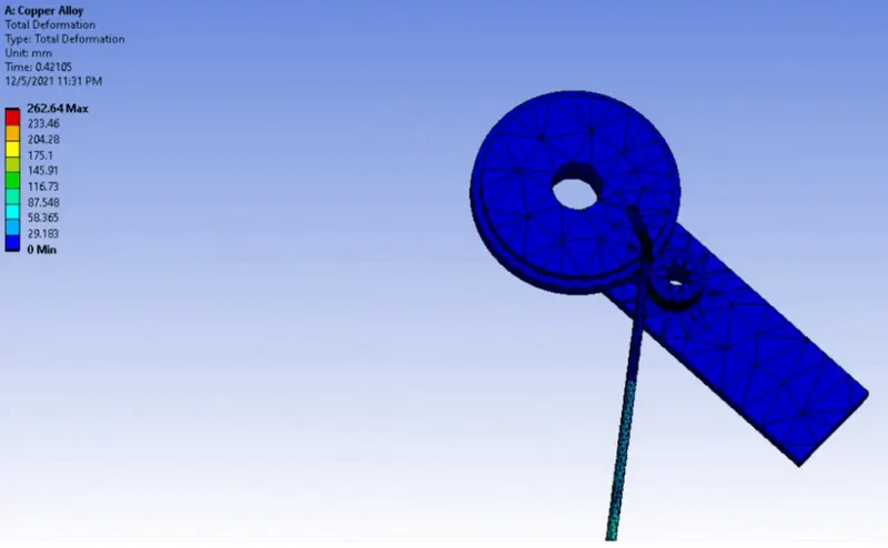
The total deformation is max. 262.64mm as shown below.
CASE 2
By using the Aluminum alloy for wire.
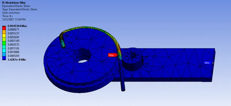
The elastic strain for the given component will be max. of 0.0045304mm and min of 7.98e-8 mm as shown below.
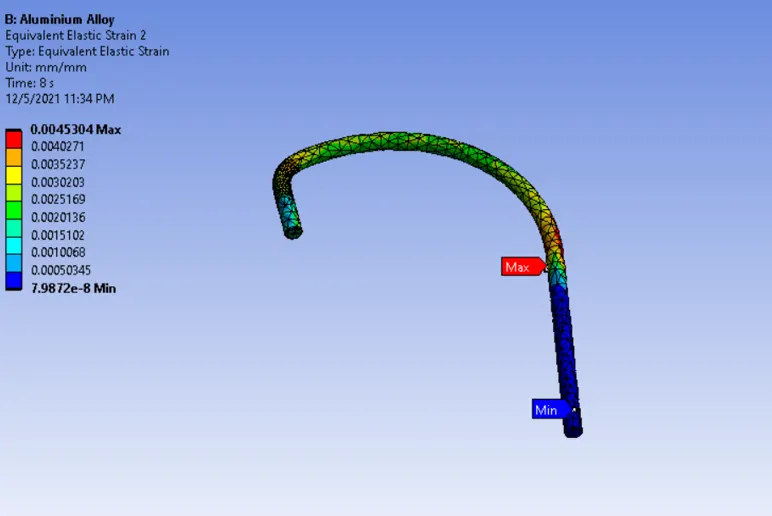
The elastic strain of the component will be recorded at 0.0045304mm as shown below.
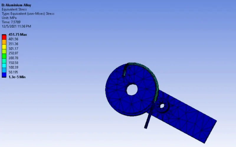
The equivalent stress recorded max. of 451.75MPa is shown below.
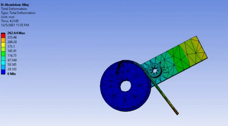
The total deformation will be 262.64mm as shown below.
CASE 3
In this case, magnesium alloy will be used.
The elastic strain for the given component will be max. of 0.0057676mm and min of 7.942e-8 mm as shown below.
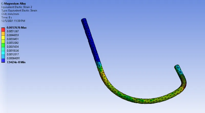
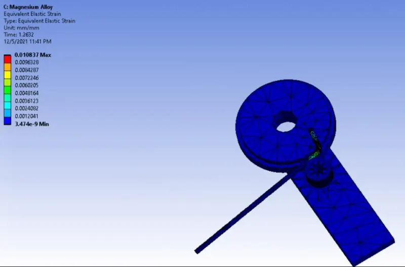
The elastic strain of the component will be recorded at 0.010837mm as shown below.
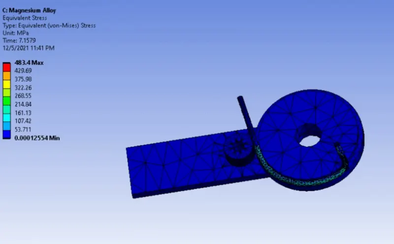
The equivalent stress recorded max. of 483.4MPa is shown below.
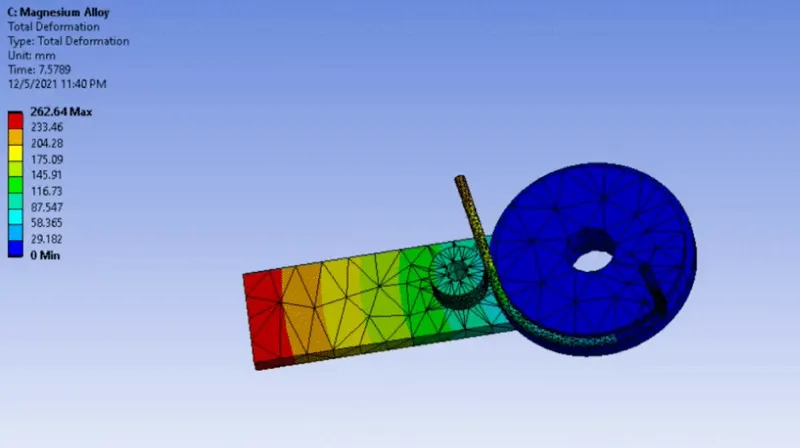
The total deformation will be 262.64mm as shown below.
Results
The results of case 1, CASE 2, and case 3 have been recorded in the below-shown table.
| Total Deformation | The elastic strain of wire | Elastic strain | stress | |
| CASE 1 | 262.64mm | 0.0031749mm | 0.0059582mm | 647.51MPa |
| CASE 2 | 262.64mm | 0.0045304mm | 0.0045304mm | 451.75MPa |
| CASE 3 | 262.64mm | 0.0057676mm | 0.010837mm | 483.4MPa |
Conclusion
- For the wire bending model, the total deformation will be the same for all the cases of 262.64mm.
- The elastic strain of wire is max. in magnesium alloy of 0.010837mm and min is for a copper alloy of 0.00317mm.
- The elastic strain of wire max. 0.0059582mm for copper alloy and min. will be 0.010837mm as shown in the table.
- The equivalent stress is been recorded max. of a copper alloy of 647.51MPa and min of a magnesium alloy of 483.4MPa as shown above table.