Week 1 Spur Gear Challenge
Aim- To perform the static structure analysis for the spur gear.
Introduction
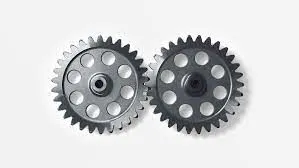
- By using gear trains, a large velocity ratio can be obtained with minimum space.
- Gears are mechanically strong, so higher loads can be lifted.
- Gears are used for transmission of large H.F.
- They are used for transmitting motion over a small center distance of shafts.
- Transmissions.
- Conveyor systems.
- Speed reducers.
- Engines and mechanical transportation systems.
- Gear pumps and motors.
- Machining tools.
Procedure- To start the simulation by opening with the Ansys workbench.
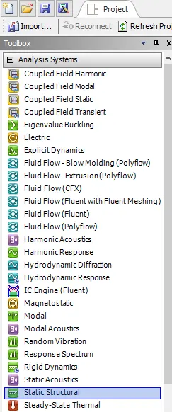
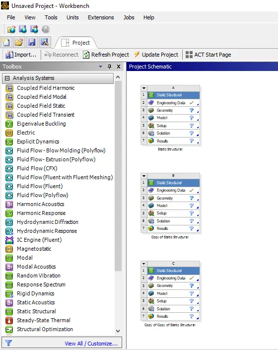
Select the static structure from the toolbox as shown below shown.
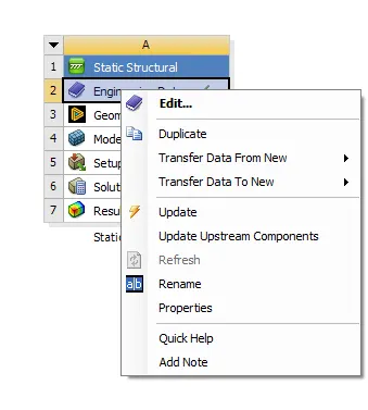
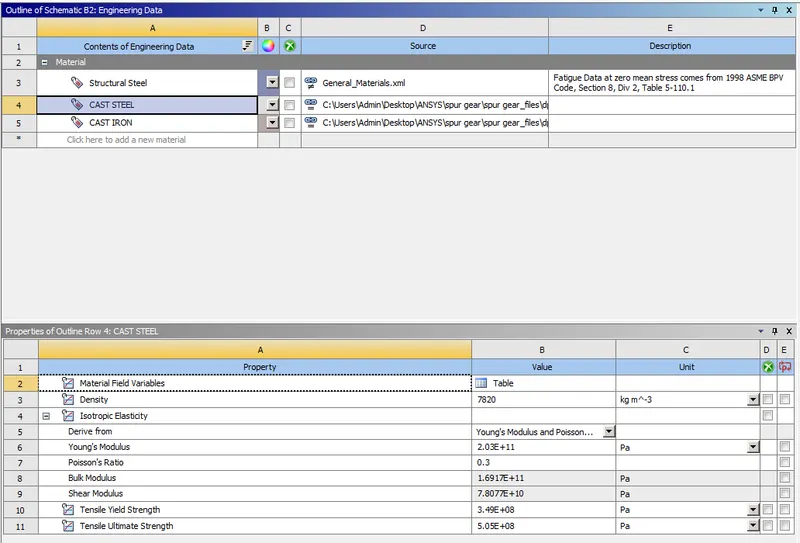
In static structural select to assign the material property in engineering data.
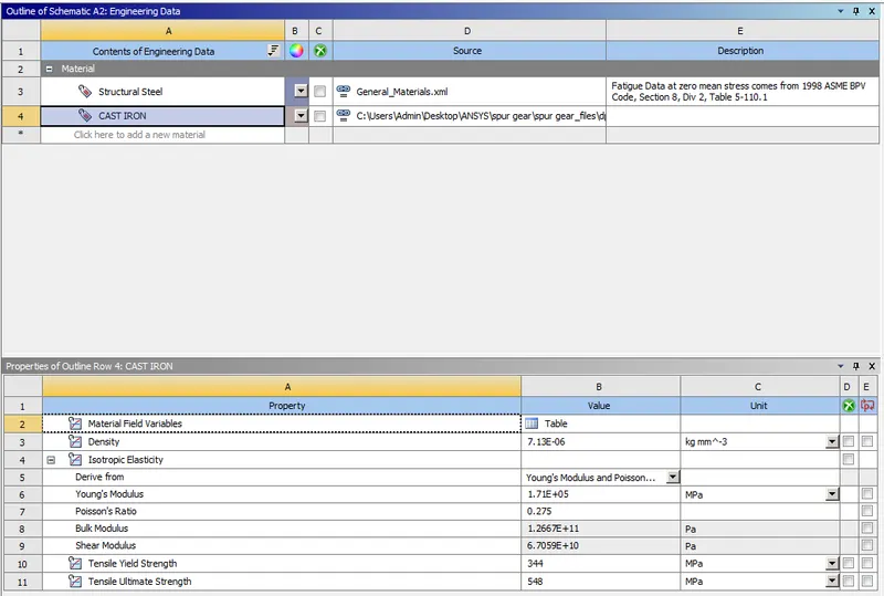
Then select the material as the cast iron and assign the properties of the cast iron, Assign all proper parameters to be dragged and assign the parameters into it.
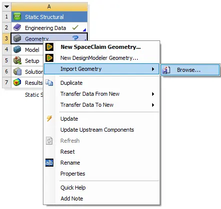
Update the engineering data and also import the geometry from the browse with the updated geometry.
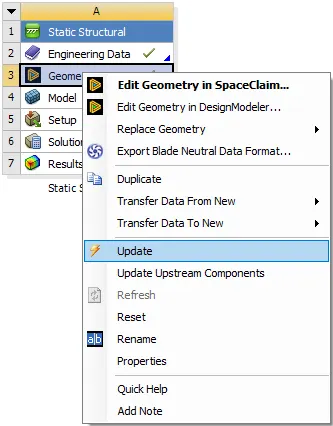
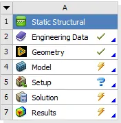
After updating the geometry double click on the model, its popup with the model window.
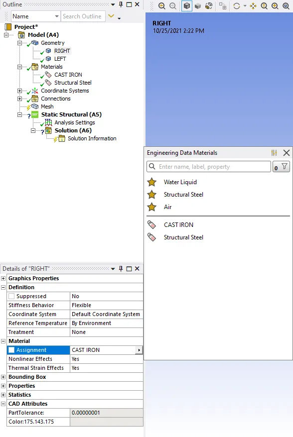
The selection in the material as the cast iron is shown below.
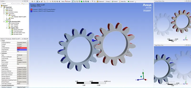
In connections have contacts of the contact region is to be select the gear teeth in the such a way that, select the teeth faces as shown in the video. Also, select the behavior as symmetric.
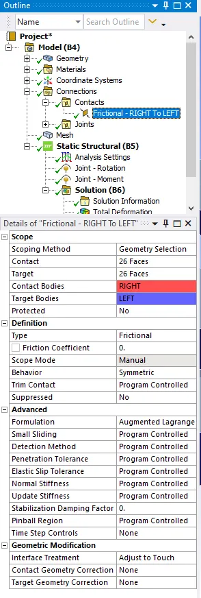
After selecting the contacts of both gear teeth of contact bodies and target bodies as shown below.
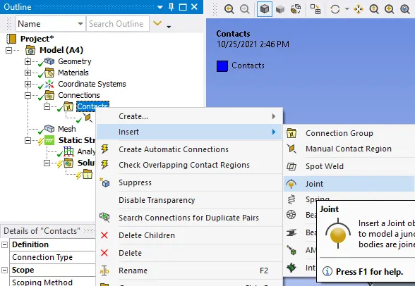
After selecting the contact region create the contact for the joint as shown below.
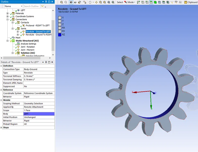
The below-shown image has been selected the parameters as shown below.
Connection type- Body- Ground
Type- Revolute
Scope- Inside the face of the gear.
Body-Left
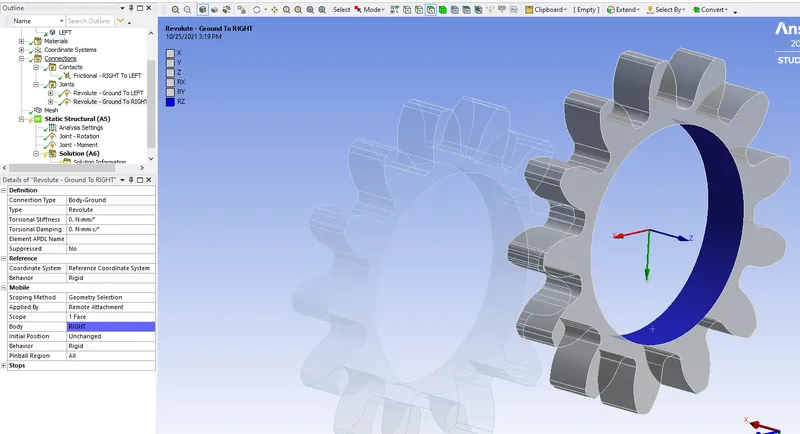
Similarly for the right side of the body as shown in below.
Connection type- Body- Ground
Type- Revolute
Scope- Inside the face of the gear.
Body-Right
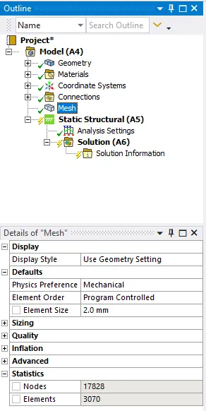
Select the mesh size as 2mm and set units according to the parameters.
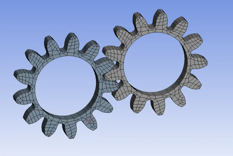
After meshing of both gears as shown in below.
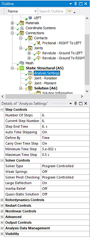
Do the necessary static structural analysis settings of step controls as shown in the video that has been assigned below.
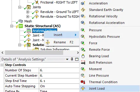
In analysis, settings insert the joint load as shown below.
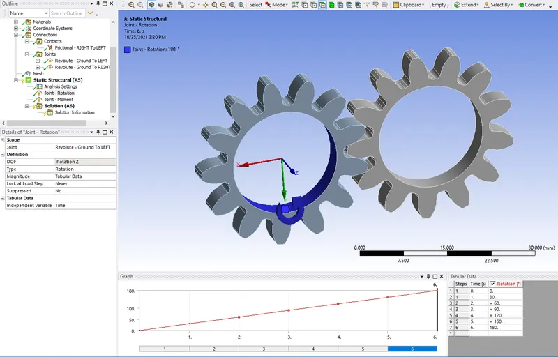
By creating the joint loads of the DOF and selecting the type as rotation and selecting as shown below with set the animation step of 6 sets the time and rotation.
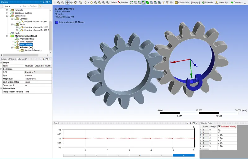
Similarly for the other joint has been selected DOF as the rotation and selected the type as the moment as shown in below.
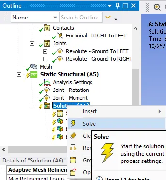
The model is ready for the simulation so, select the solution and solve as shown below.
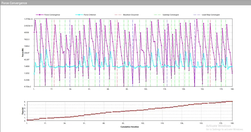
While solving the static structure of the forced conversion and force criterion w.r.t cumulative iterations as shown below.
This is a static analysis of the time factor we cannot use but here time we can use as the counting for the steps to solve.
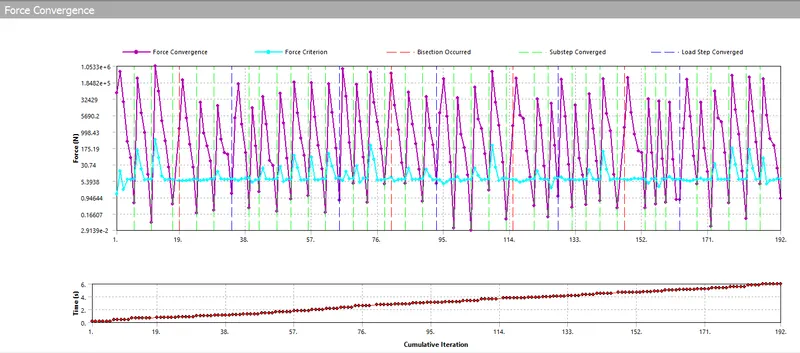
Case 1 Cast Iron
It will take some time for the simulation and analysis of the results of the Total deformation, Equivalent strain, and Equivalent stress.
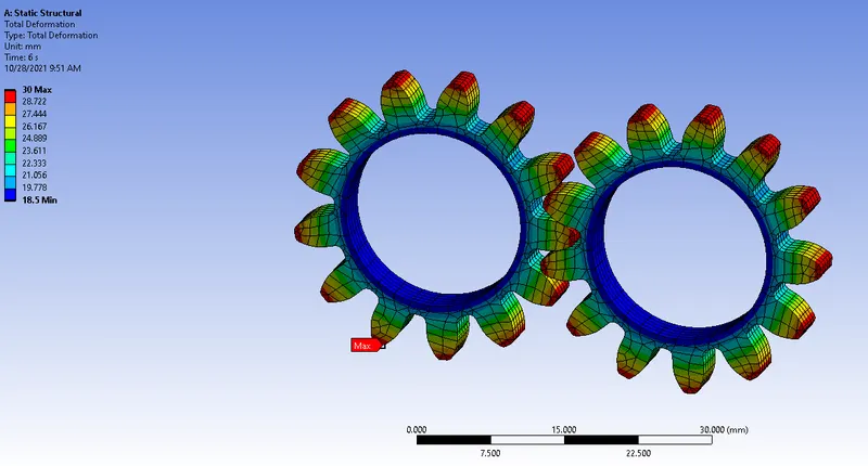
The below shown the total deformation has been shown max at 30 mm and min is showing as the 18.5 mm as shown in below.
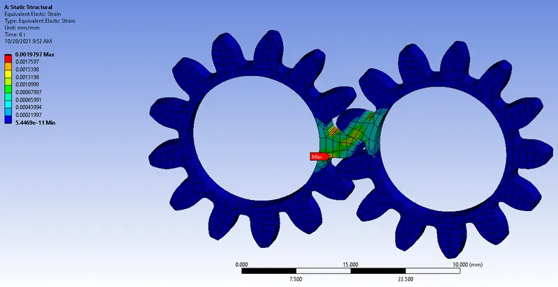
The elastic strain has been showing a max of 0.0019797 and a min of the 5.4469e-11 as shown below.
The FOS for the spur gear has to check and with ultimate load to the allowable load. By calculating and comparing the results with the original.
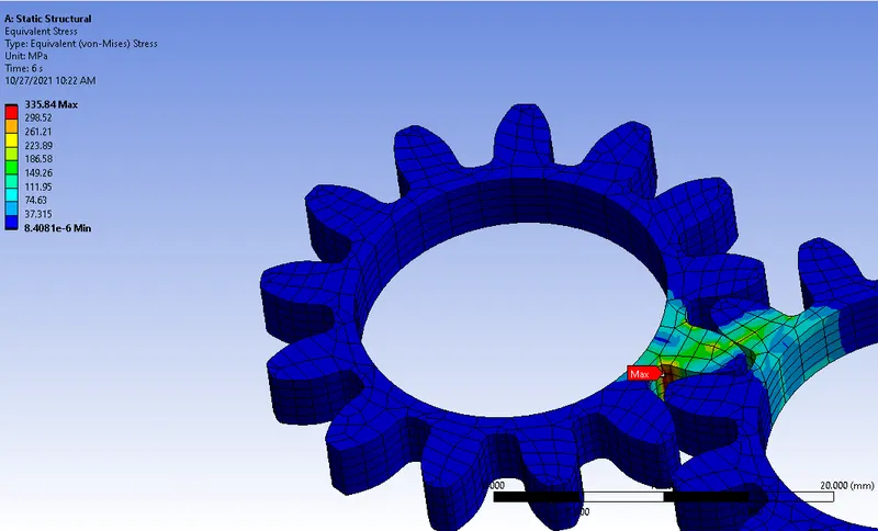
The equivalent stress is of max is showing as 335.84 MPa and min. is of 8.4081e-6MPa as shown below.
The factor of safety=Yield strength /Allowable Load (Stress)
= 344/335.84
=1.02
By calculating the FOS has been found 1.02 the material will not fail. The material that has been chosen will be quite safe.
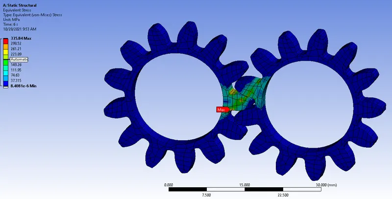
The stress concentration will be more in the gear teeth so, the stress intensity is of the max probe is as shown below.
Similarly for case 2 and case 3, repeat the same procedure by copying the static structure. Case 2 and case 3 only change in the model as the material property of cast iron and cast bronze respectively as shown below.
Case 2. Cast steel
Assign all required parameters for cast steel has been assign into the engineering data.
While solving the static structure of the forced conversion and force criterion w.r.t cumulative iterations as shown below.
This is a static analysis of the time factor we cannot use but here time we can use as the counting for the steps to solve.
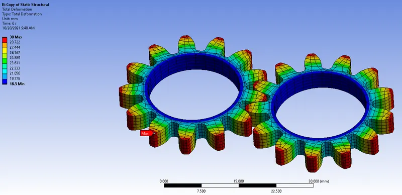
The below shown the total deformation has been shown max at 30 mm and min is showing as the 18.5 mm as shown in below.
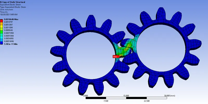
The elastic strain has been showing a max of 0.0019797mm and a min of the 5.4469e-11 as shown below.
The FOS for the spur gear has to check and with ultimate load to the allowable load. By calculating and comparing the results with the original.
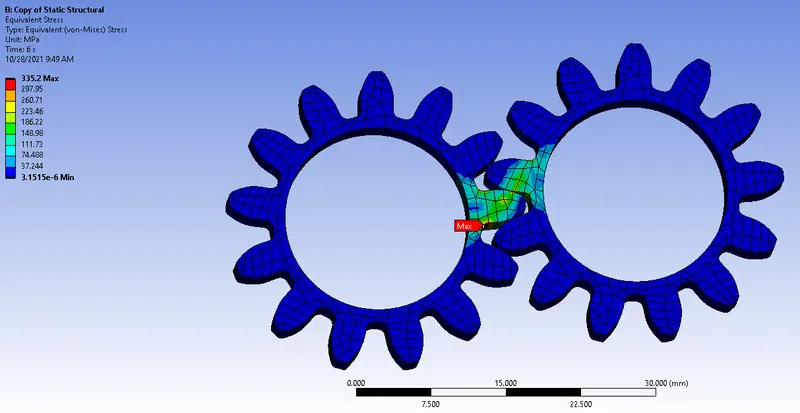
The equivalent stress is of max is showing as 335.2 MPa and min. is of 8.1515e-6MPa as shown below.
The factor of safety=Yield strength /Allowable Load (Stress)
= 344/335.2
=1.02
By calculating the FOS has been found 1.02 the material will not fail. The material that has been chosen will be quite safe.
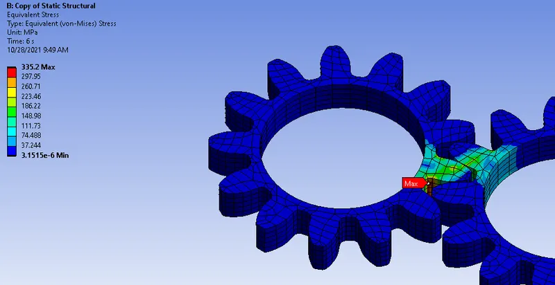
The stress concentration will be more in the gear teeth so, the stress intensity is of the max probe is as shown below.
Case 3 Cast Bronze
Assign all required parameters for cast steel has been assign into the engineering data.
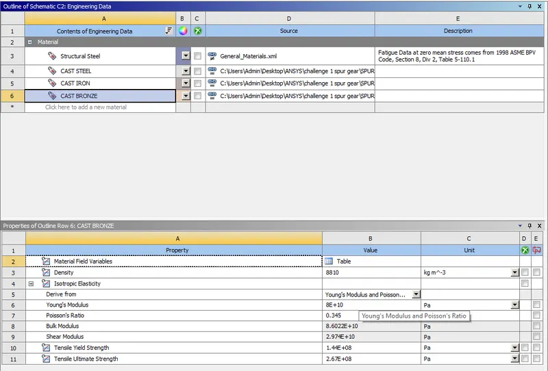
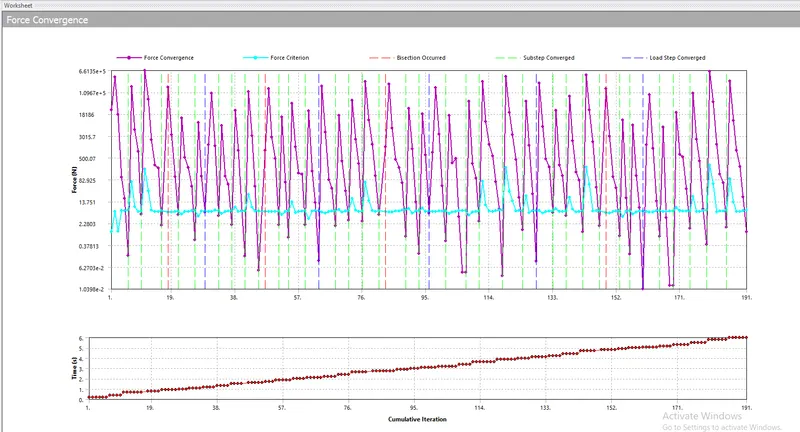
While solving the static structure of the forced conversion and force criterion w.r.t cumulative iterations as shown below.
This is a static analysis of the time factor we cannot use but here time we can use as the counting for the steps to solve.
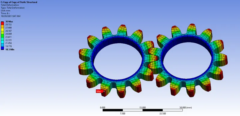
The below shown the total deformation has been shown max at 30 mm and min is showing as the 18.5 mm as shown in below.
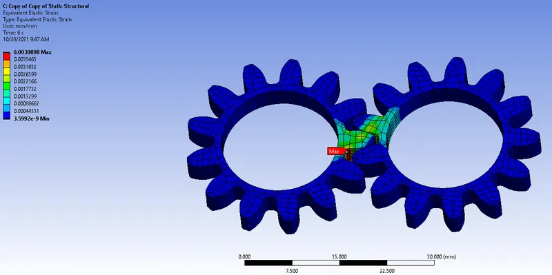
The elastic strain has been showing a max of 0.0019797mm and a min of the 5.4469e-11 as shown below.
The FOS for the spur gear has to check and with ultimate load to the allowable load. By calculating and comparing the results with the original.
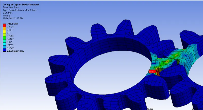
The equivalent stress is of max is showing as 316.5 MPa and min. are of 8.1515e-6MPa as shown below.
The factor of safety=Yield strength /Allowable Load (Stress)
= 144/316.5
=0.4
Now it's less than 1 so, again check by using the ultimate strength.
The factor of safety=Ultimate strength /Allowable Load (Stress)
= 267/316.5
=0.8
By calculating the FOS for both it will be less than 1. In both cases the FOS is showing less than 1 so, it's under the plastic deformation so, it's not preferable to use.
By calculating the FOS has been found 1.02 the material will not fail. The material that has been chosen will be quite safe.
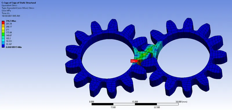
The stress concentration will be more in the gear teeth so, the stress intensity is of the max probe is as shown below.
All results are have been tabulated as shown below.
| Total Deformation | Elastic strain | Stress | FOS | |
| Cast Iron | 30-18.5 | 0.0019797 mm | 335.84 MPa | 1.2(Safe) |
| Cast Steel | 30-18.5 | 0.0019797 mm | 335.2 | 1.2(Safe) |
| Cast Bronze | 30-18.5 | 0.0019797mm | 316.5 | 0.8(Unsafe) |
By comparing with all results for the 3 different materials of total deformation and the elastic strain have same results for the 3 cases.
The compering the stress will be varying with the material we selected. The material to be safe will be cast iron and cast steel because the FOS is greater than the 1. so, these materials are quite safe.
For the Cast bronze has been shown the values of less than 1 usually FOS of material is unsafe.
Conclusion
By doing this static structural analysis case of spur gear is to know the different material how the FOS is to be considered.