Week 4-1D Element Creation Challenge
Answer
As per the given question component will create a mid surface for both top and bottom separately
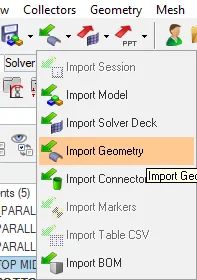
Select import geometry, go to file selection in IGES file.
After import component should be fit
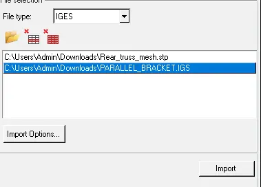
The component in the IGES file for ready to do. by taking this component delete the unnecessary lines in the component.
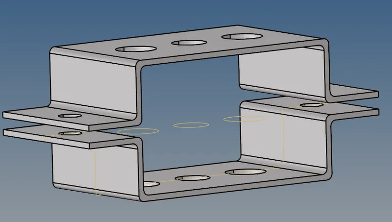
Select line and display select delete entity. as above given component there are unnecessary drawing lines are there so, they should remove.

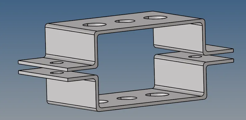
Make the component will free from the unnecessary line as given below.
First, go for the geometric, select mid surface for component, the select auto mid surface of auto extraction.
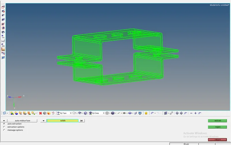
For this component, the mid surface is not done with one component so, select create a component and make a separate model for each.
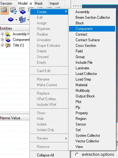
After creating a separate model for both the top and bottom of the component, select the required color code for both the model.
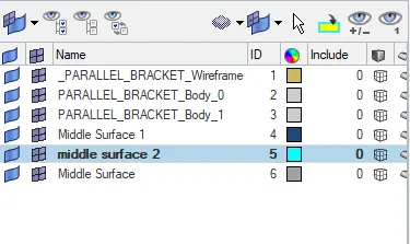
By the mid surface of having for both top and the bottom component will extract in different model respectively.
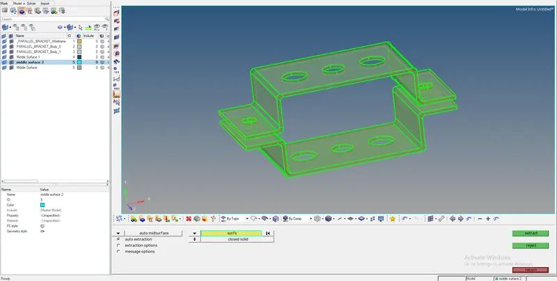
Delete the entire solid component by selecting solid and displayed, and delete the entity.
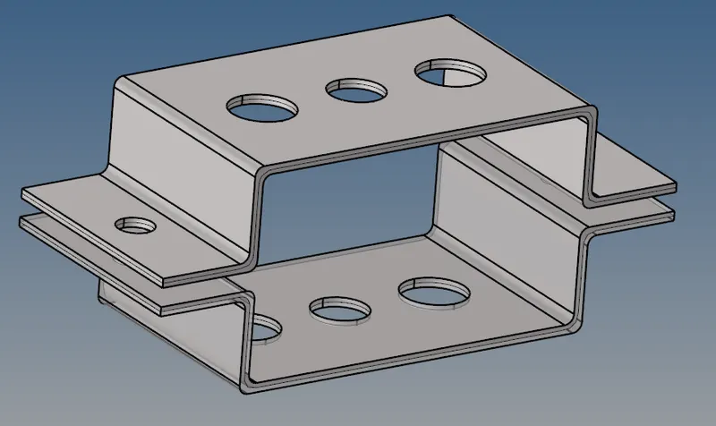
After making a mid surface for the given component is to delete the solid part from the component.
go to delete, select the solids, select displayed, delete an entity, and return.
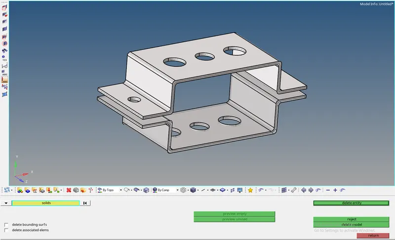
The solid part is deleted but not displayed. so, delete unnecessary components to make mid-surface components.
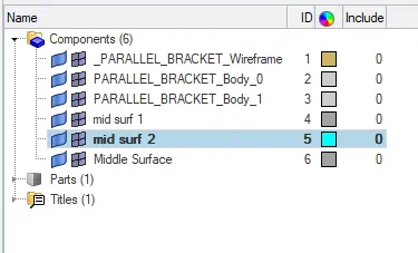
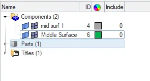
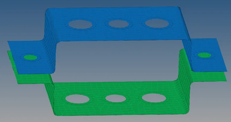
The component looks like the below-given.
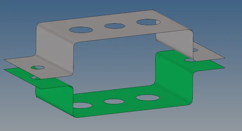
Check the given color of the model is correct or not so, to get the proper color code. go for tools, organize, by selecting the model and select color, select model and move, return.

Assign the material property for the component. create material and naming as steel with color code.
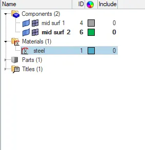
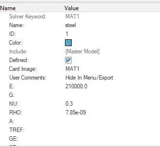
Assign the material like steel and taking values thickness of 5 units and also assign the value for young modulus, Poisson's ratio, bulk modulus, to the steel material.
Select property and select create a select property, select the property for the mid surf 1 and mid surf 2 respectively. the thickness for both the property is 5 units.
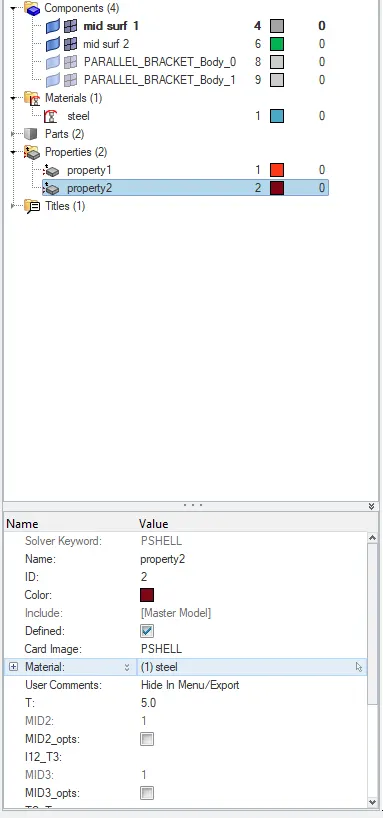
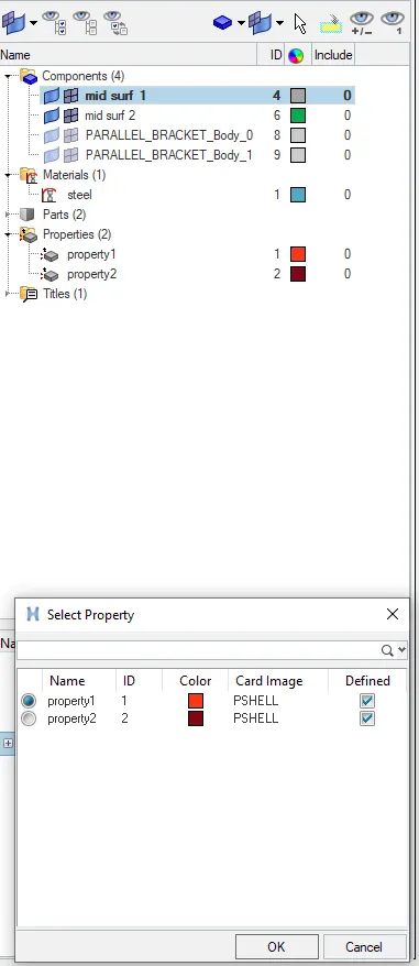
For mid surf 1 and mid surf 2 assign material property 1 and property 2 respectively.
After finishing the assigning property, create the washer split for all holes in the component. so, select geometry, select quick edit.
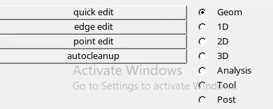
Select the washer split of value offset value of 5 units and return.

Select all holes given in the component and create the washer split for the component.
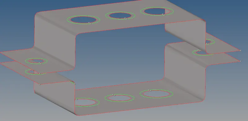
The above component is ready for the mesh.
Go for 2D, select auto mesh surface to select the component, and give the element size as 8mm, select mesh type as mixed, click on the mesh.

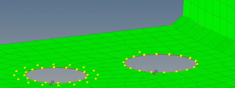
The mesh is created but for holes, the elements are not matched within symmetric so, set the elements to have symmetric holes by increasing the nodes.
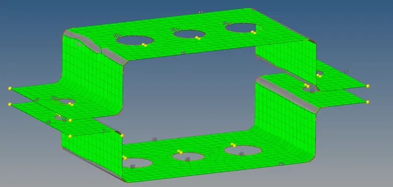
like this increases the nodes and creates nodes for symmetric nodes to the component. select return.
The final mesh part is given below.
further create the different loads,, material property, elasticity, etc. and the given component, create Rbe2 and Rbe3 with as per the requirement.
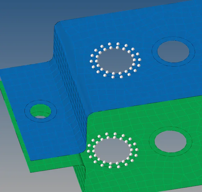
select the Rbe2, for nodes select the by path, select nodes where should apply for the same.

one by one selecting the nodes and apply the Rbe2 nodes for the component, select return

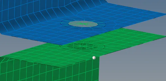
for simultaneously apply Rbe2( for a,d and e) for different DOFs and of the different surfaces can apply.
`
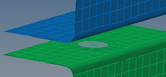
The same condition applies Rbe3 (for b and c)and DOFs for the component with respect to given conditions.

The finally get Rbe2 and Rbe3 components look below shown.
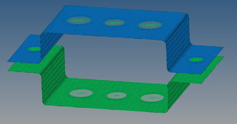
For the component should apply the masses of D and E holes.

Select the nodes, the element type is CMASS, and mess magnitude will select as 10, create and return.

The finally CMASS has been created as shown below.
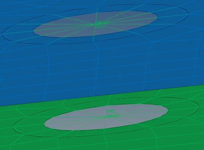
Assign the given conditions for ROD, BEAM, BAR for given components with respect to given conditions.
select the 1D and select hyper beam. select a standard section, select std section type create.

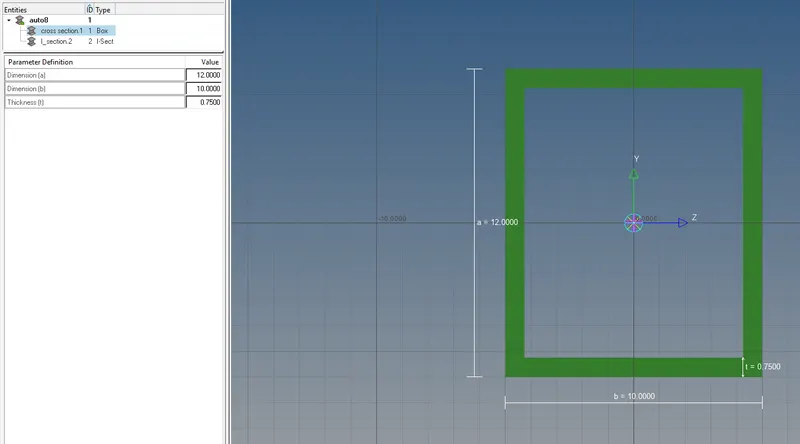
Enter the parameter is required for the ROD to assign the dimensions for the rod 12*10*0.75 for the ROD condition.
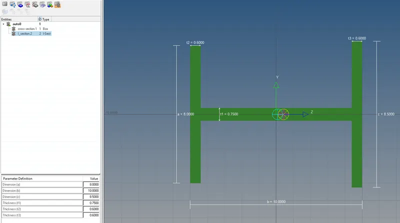
For the second conditions given for BEAM of I section a=8mm,b=10mm,c=8.5mm, t1=0.75,t1=0.6,t1=0.6. respectively shown in below.
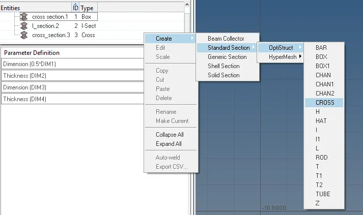
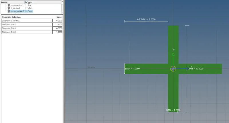
In special cases, the condition has been given BAR has been given as the X cross-section so, select create, standard section, obstruct, select cross.
Enter the parameters are given in statement DIM 1=5MM,DIM 1 (t)=1.2MM,DIM 1=10MM,DIM4 (t)=1.2MM.
After assigning all parameters for ROD, BEAM, BAR so, that apply these for a particular section.
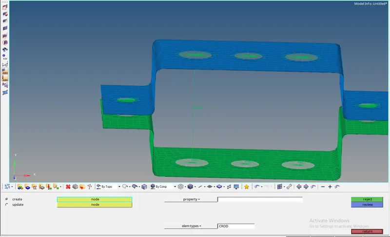
Go to 1D, select ROD, select nodes between ROD, select the elemental types CROD and update for particular nodes.
, 
In the bar option only created beam( CBEAM), it seems as bar 2. select the nodes where should we place the BEAM. select the Rbe 3 nodes
For load distribution, select node N1, N2, N3, and update and return.

In the same manner for selecting the BAR and select the element type as CBAR. select both nodes and create on one plane to select the N1, N2, N3 for the component.

After assigning all parameters of ROD, BEAM, BAR it looks like the below shown.
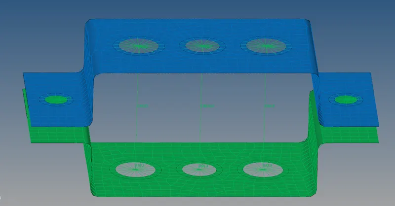
By using the property of ROD, BEAM, BAR is added for the components.
select the ROD, select card type is PROD and select rod section as we mention.
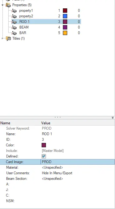
As per the statement selecting the ROD, BEAM, BAR in the same manner as shown below.
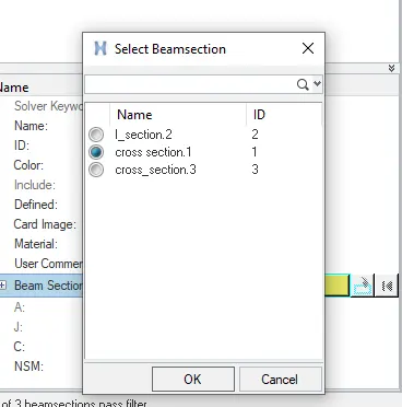
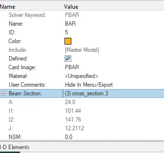
After assigning properties value update should needs to be done and return.

In its rod the property already created so, that can update assigning property for the rod.
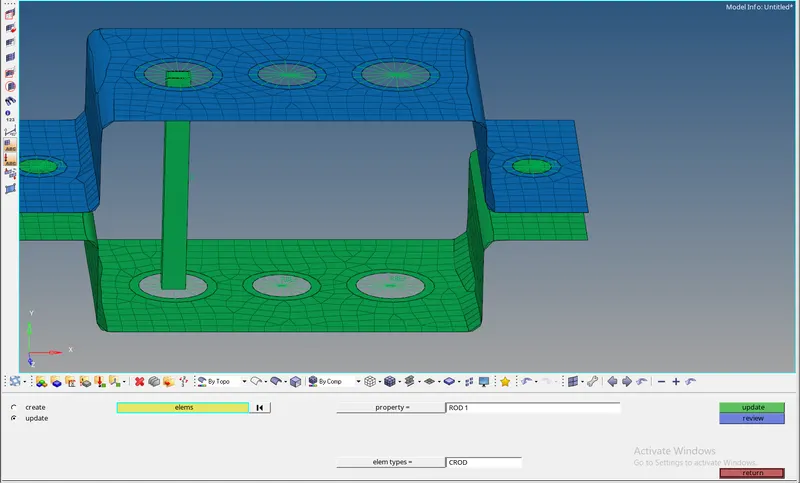
After the rod, the beam should make the update as given.
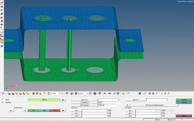
The updated component becomes as shown in below.
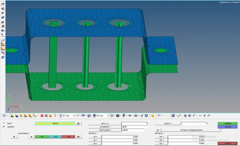
As per the given, conditions the masses are applying on the point of d and e. select elemental type CMASS and select the magnitude of 10. create, return.

Joined the 2 components with a spring element for the component.

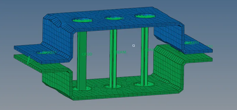
Finally, The joined Component by the spring element.

for assigning all the parameters from the statement it looks like below shown.
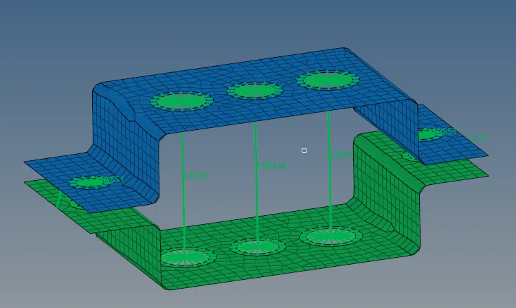
Now the component is in 1D transitional element but as per our requirement taking as1D detailed elemental representation.
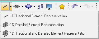
After that, the component seems like this.
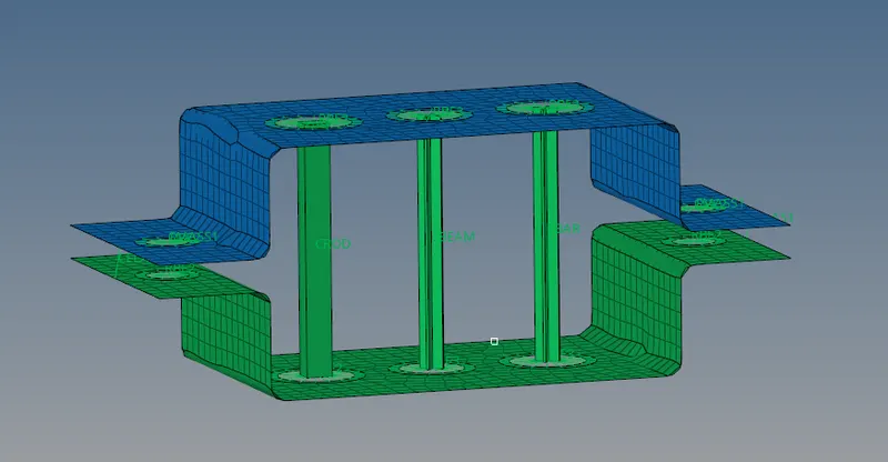
By giving thickness for the given component by using 2D detailed elements representation.
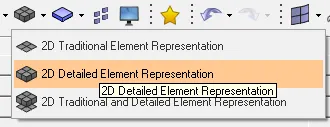
Finally got the final component as below given
conclusion
By doing this challenge, came to know that component of ROD, BEAM, BAR, and its property can assign in the component. Uses of Rbe2 and Rbe3 for the given component. The various types of masses and springs to the component will be known from making this component.