Week - 8 - Morphing
Aim - To perform the morphing for given two model and proper change in given component.
Procedure- Usually in a design cycle, FE modeling and simulations are performed once the concept CAD is generated. With the need to reduce design iterations, it will be useful if the concept changes are made in the FE model itself, taking the time required for CAD generation, off the cycle. This can be achieved by CAE Morphing. Morphing as the name suggests is an adaptation of given shape to a new form. The same concept is used in case of mesh morphing. In this method, the concept model or the donor model can be modified/altered to required proportions to create new designs using morphing techniques.
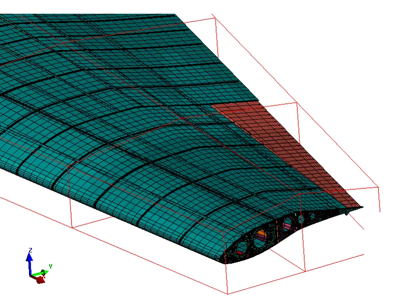
CAE function encompasses a feature based morphing tool that can rapidly morph existing FE and CFD models to match new geometry and/or to new proportions. Component and full system level FE/CFD models (such as automotive vehicle crash, NVH and durability models) can be morphed to fit target design features such as styling lines, sections, proportions etc., precisely. A wide variety of in-built morphing techniques such as control block (lower and higher order), direct parabolic, spherical, polycube and field based morphing are available to address varied applications. An extensive set of automated and interactive tools to create ‘control blocks’ for assembly level morphing is available.
The comparison chart here shows that with the help of ANSA morphing techniques the error rectification or design change takes considerably very less amount of time as the change is done directly to the FE model. The overall lead time of the product is drastically reduced with the help of ANSAs Morphing, thus increasing the overall cycle efficiency.
what is morphing
Morphing is an adaptation of given shape to a new form.
The geometry of a given concept model can be modified to required proportions to create new designs.
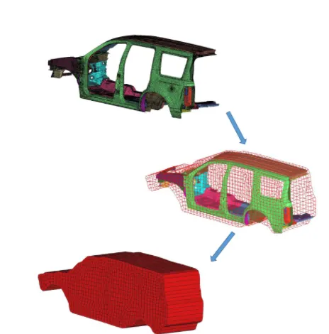
CAE Morphing allows users to work on the FE mesh directly reducing the time taken to go back to the designer to update the geometry.
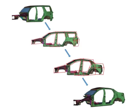
Full vehicle morphing
Why CAE Morphing?
Minimizes time spent on design modification by working directly at the mesh level.
Automatic control block creation methods require less skill and effort and allow fast and efficient design creations using parameterized optimization.
Easy transformation of CAE models from the original design to a new concept.
Keeps your connections (contacts, boundaries, loads, bolts, welds, etc) from the current to the updated model.
Benefits:
- Minimizes time in design modification by directly working at mesh level thus improves the overall lead time.
- Automatic control block creation methods requires less skill and effort, avoiding high expertise, leading to time reduction in development and design.
- Fast and efficient design creations using parameterized optimization.
- Easy morphing of CAE models from parent design to a new concept or to match design specifications for two components derived from different parent designs.
- Creation of ‘n’ number of parameters for different designs, enabling easy trial and error method of design correction.
For given component perform the morphing.
Component 1-First import the component in to the GUI
Do the primary settings for the component like orient and make it topo.
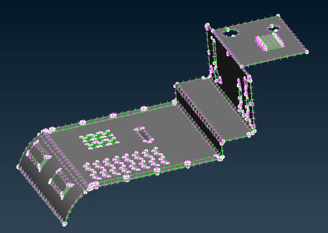
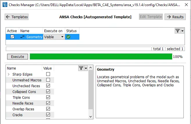
Check the component for the geometry and execute the all the errors.
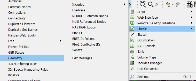
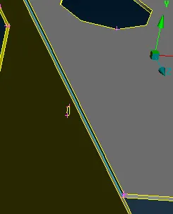
As shown in below the arised tripple cons error can be fix.
These kind of tripple cones issues can be solved
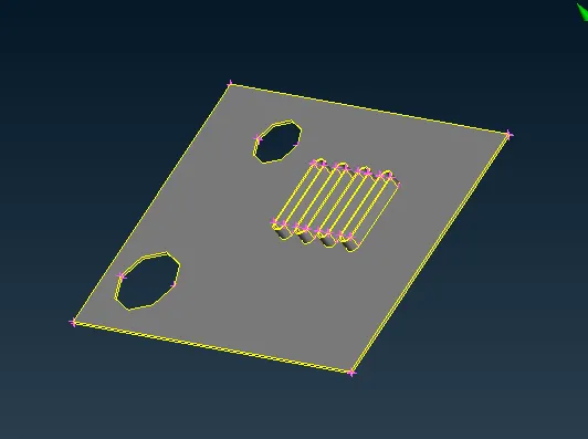
Make the seperate PID for the component as per the thickness.
select the Morph deck to perform the morph operation.
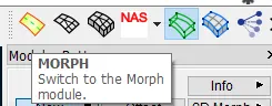
Select the boxes and select the new option.
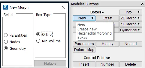
Make the box by selecting box type ortho and geometry.
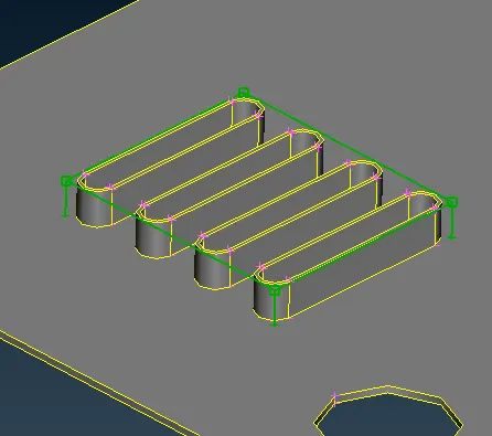
After selecting box selection move that box as requred distance.
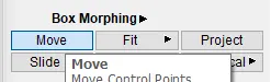
By selecting the co-ordinate also make the extend the selected part.
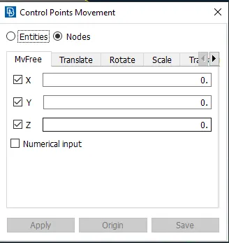
As below shown the modification can be done as shown in video
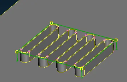
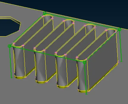
Similarly for the middle of the component do the box selection as shown in below.
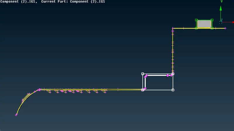
Did the modification as shown in below .
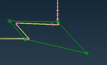
For the same coponent did modification what we requred as shown in below.
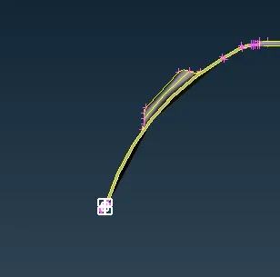
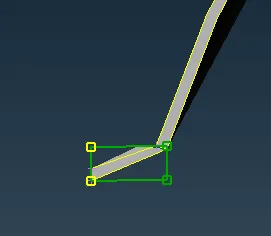
After performing the morph operation delete the boxes what we are morph has created.
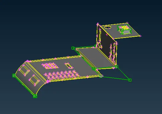
Make the full box selection for the component as shown in below.
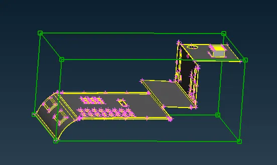
Do the modification by selecting the nodes and selcting the move and required.
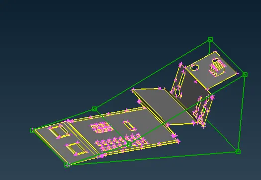
After doing the modification it has been created as shown in below.
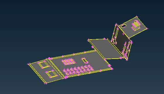
The final component after deleting the boxes shown in below.
Component 1-First import the component in to the GUI
Do the primary settings for the component like orient and make it topo.
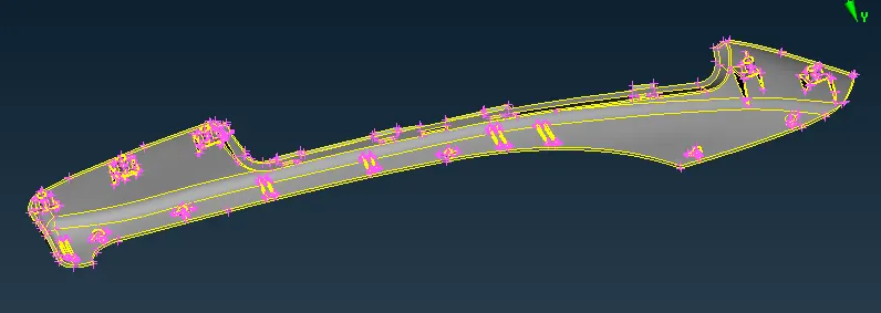
Check the component for the geometry and execute the all the errors.
As shown in below the arised tripple cons error can be fix.
These shown region are to be perform the morph for the component.
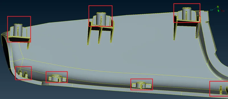
Use the iNOT option and make the selection.

Select the dog house perticularly and make the independent part.
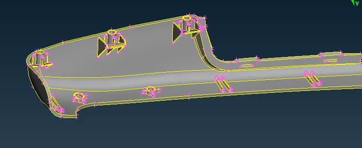
By using the iNOT option and make the single.
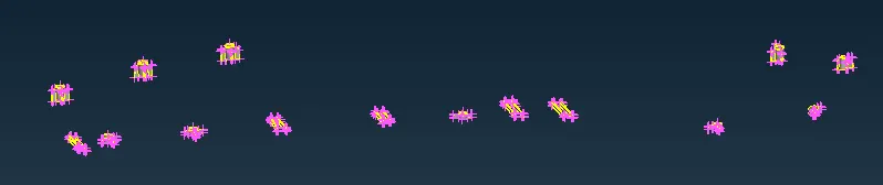
select the Morph deck to perform the morph operation.
Select the boxes and select the new option with the geometry by min voiume.
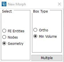
Make the box by selecting box type ortho and geometry.
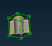
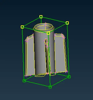
Select in box morphing as move and select the nodes
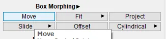
With the proper direction select the nodes to be strech.
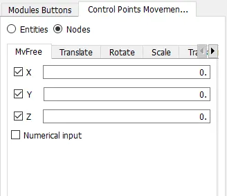
With the below the shown ribs also make the modification.
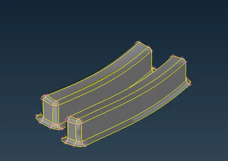
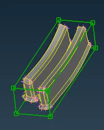
After modification the component looks like as shown in below.
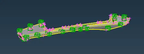
The boxes can be delete by selecting the boxes.
After modification the component as shown in below.
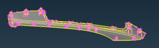
Conclusion
For doing this morphing to know the various commands to perform the morphing. The component or assembly component can be modify by doing this morphing.