Week 3 Verification of Weld Joints
Aim- To perform the static structural for the given welding component.
Objectives
The given welding model does the preprocessing, solver, postprocessing.
Case 1. Solve by using stainless steel as welding material.
Case 2. Solve by using aluminum alloy as welding material.
Case 3.Solve by using Bronze is used as welding material.
Introduction
What is welding?
Welding is a fabrication process whereby two or more parts are fused together by means of heat, pressure, or both forming a join as the parts cool. Welding is usually used on metals and thermoplastics but can also be used on wood. The completed welded joint may be referred to as a weldment.
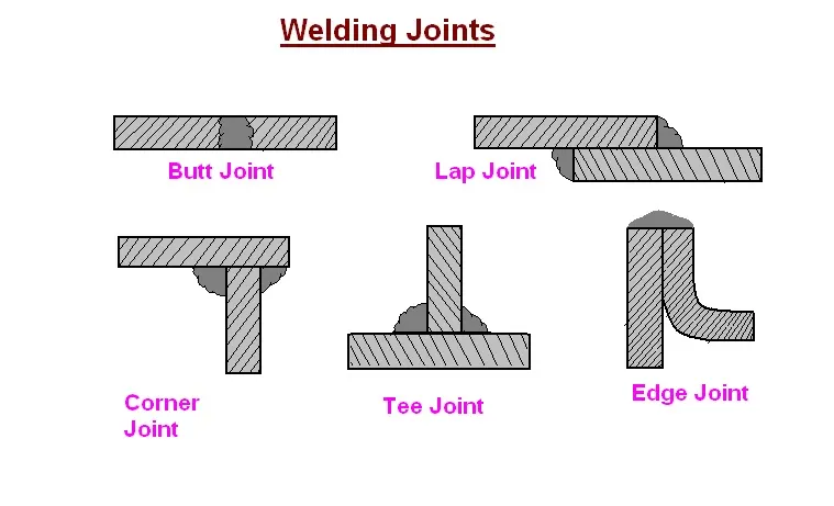
Types of welding joints
Butt Joint
A connection between the ends or edges of two parts makes an angle to one another of 135-180° inclusive in the region of the joint.
T Joint
A connection between the end or edge of one part and the face of the other part, the parts making an angle to one another of more than 5 up to and including 90° in the region of the joint.
Corner Joint
A connection between the ends or edges of two parts makes an angle to one another of more than 30 but less than 135° in the region of the joint.
Edge Joint
A connection between the edges of two parts makes an angle to one another of 0 to 30° inclusive in the region of the joint.
Lap Joint
A connection between two overlapping parts makes an angle to one another of 0-5° inclusive in the region of the weld or welds.
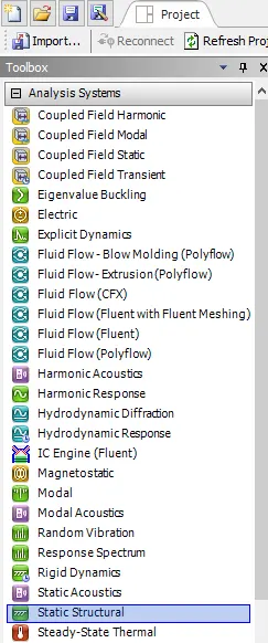
Procedure- To start the simulation by opening with the Ansys workbench.
Select the static structure from the toolbox as shown below shown.
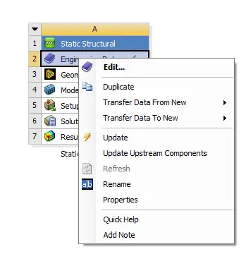
In static structural select to assign the material property in engineering data.
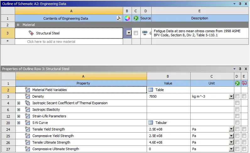
Update the engineering data as shown below.
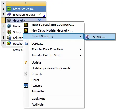
Also import the geometry from the browse with the updated geometry.
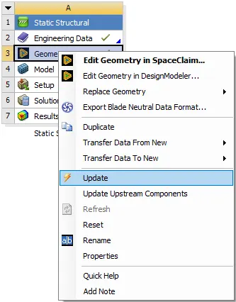
After updating the geometry double click on the model, its popup with the model window.
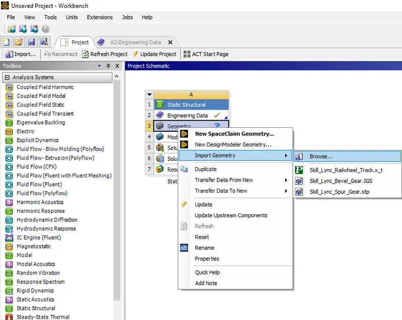
In geometry browse the geometry for the given component, as shown in the below-shown component.
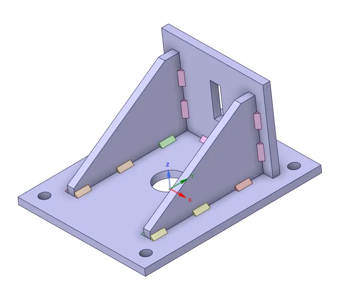
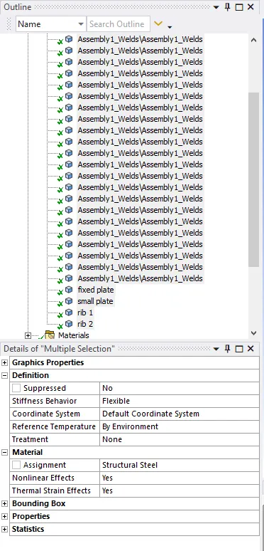
Select all the materials like structural steel by selecting all assembly components of the structural steel.
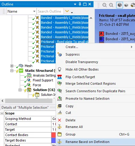
Rearrange all connections are renamed based on the definition as shown below.
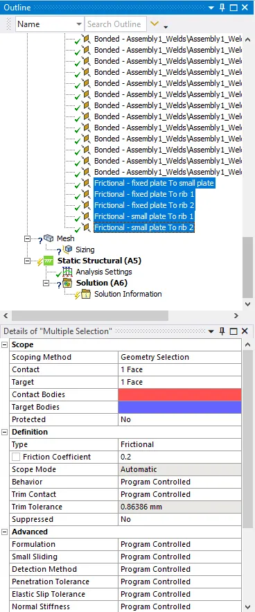
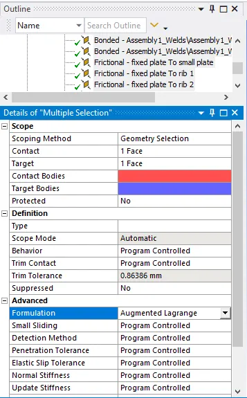
Select all fixed plates of frictional components as shown below. Select the proper contact bodies and target bodies of the component. Select the formulation augmented Lagrange as shown below.
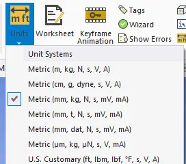
Before that select the proper unit system as shown below.
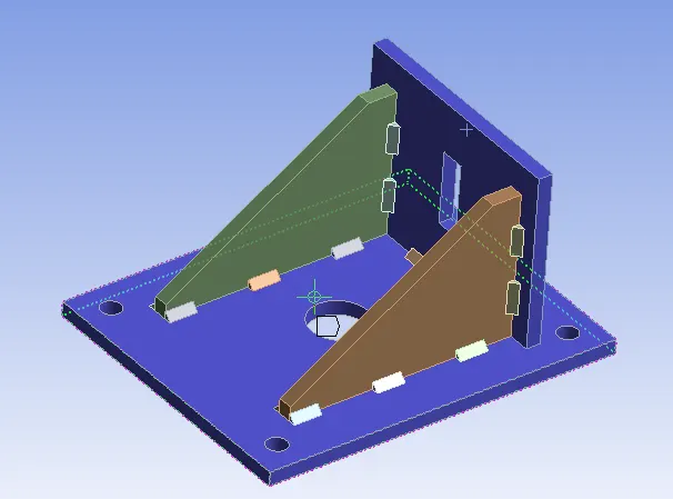
The component is the change color according to contact has been assigned as shown in below.
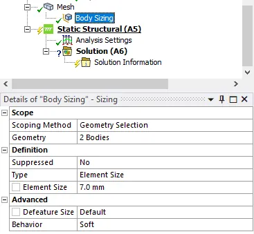
Select the mesh and select the element size as the 2mm for the weld joint and. Also the select the body sizing as 7mm for the plates and ribs as shown below.
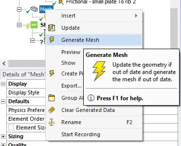
Generate the mesh as shown below.
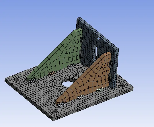
Below shown the after mesh component with the weld joints.
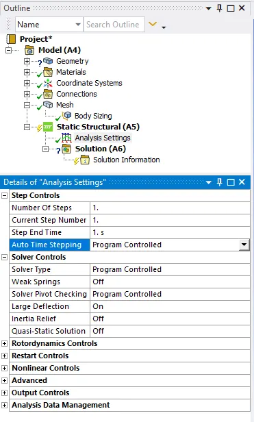
Do the proper analysis settings with assigning the step controls and server controls.
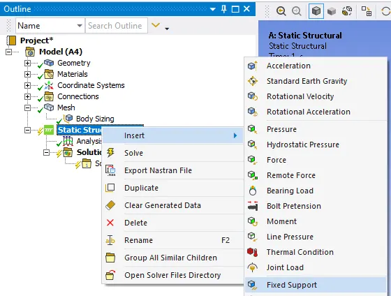
Insert the all fixed support for the given component has the big plate as shown below.
The big plate of all four holes and central holes were also selected to apply on the component as shown below.
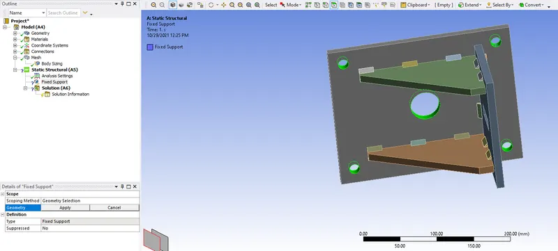
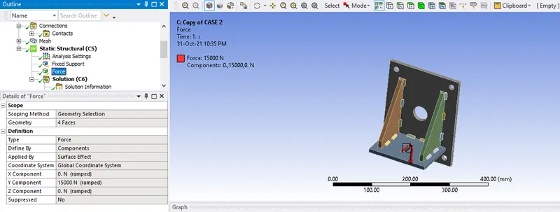
Similarly for add the force at the small face center as shown below. The force is of 15000N can be applied on the small plate center in the direction of the Y.
Select the solution that has inserted the total deformation, directional deformation, equivalent elastic strain, equivalent stress, equivalent stress 1.
Also for the stress tool as the safety factor.
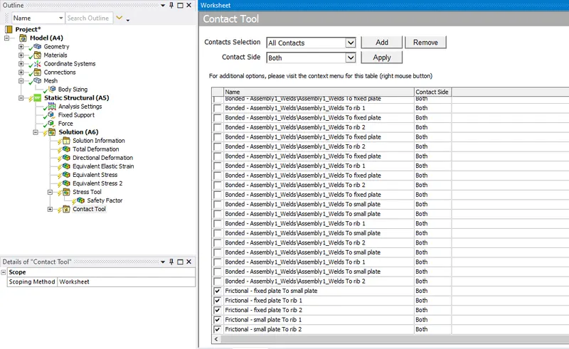
Similarly, the select the contact tool as the status and pressure have been shown in the solution.
In total deformation in definition selection, the orientation should be selected on the Y-axis.

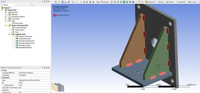
Select the equivalent stress 2 is of all weld joints and it's as shown below.
Inserting the contact tool and selecting all weldings has the untick and only tick the all frictional contact and it's shown below.
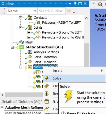
Solve after assigning all the solution parameters and start to solve the static structural analysis. It will take some time to solve the solution as shown below.
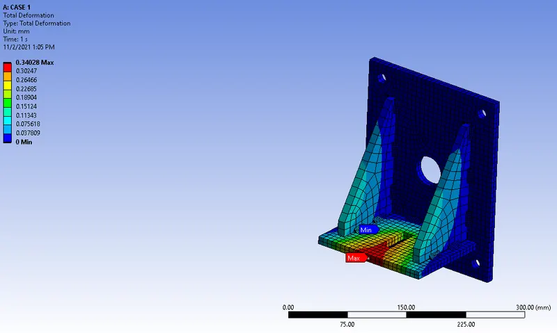
To know all deformation for the results of the display has been selected.

The total deformation has been found to be max. of 0.34028mm as shown below.
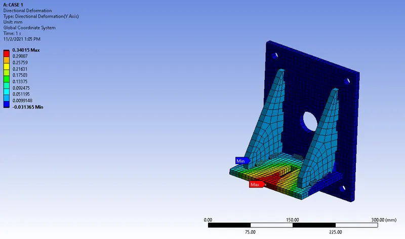
The directional deformation is found to be 0.34015mm and min of the -0.031367mm.
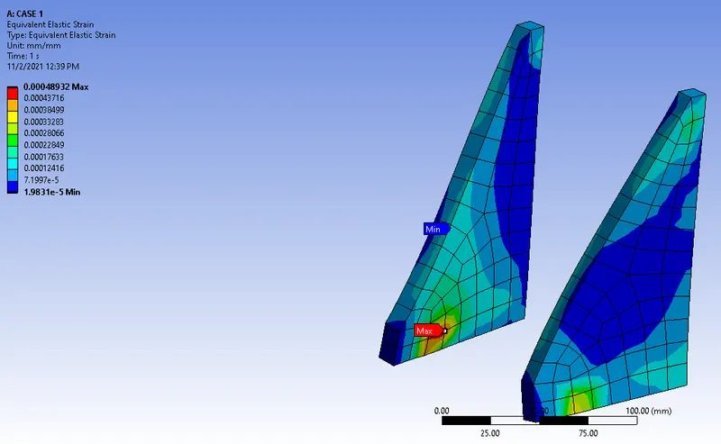
The equivalent elastic strain of max. is 0.00048932 and the min is 1.9831e-5.
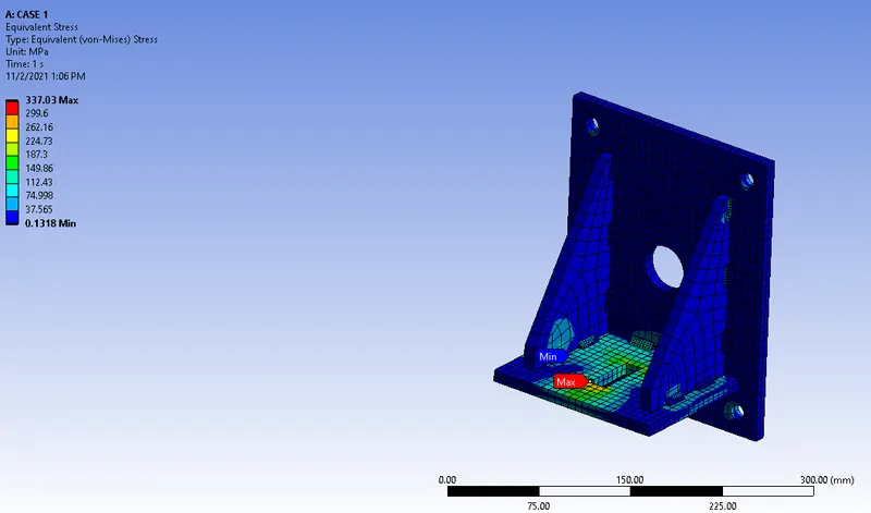
The maximum equivalent stress is 337.03MPa and 0.1318MPa is min. as shown below.
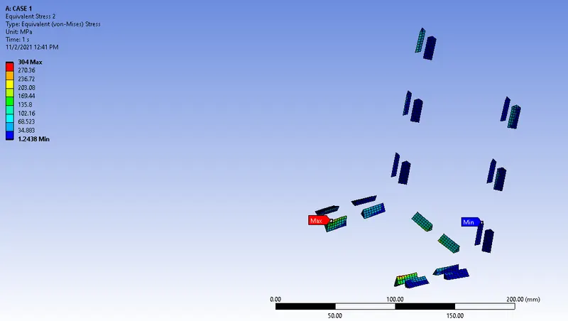
The equivalent stress is of max. 304.01MPa and min. are of 1.2465MPa welding joints as shown below.
Safety tool
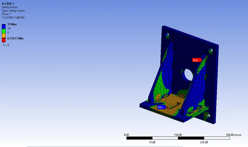
The safety factor is min. in where the load has been applied and min. of 0.74177 safety has been shown below.
Contact tool
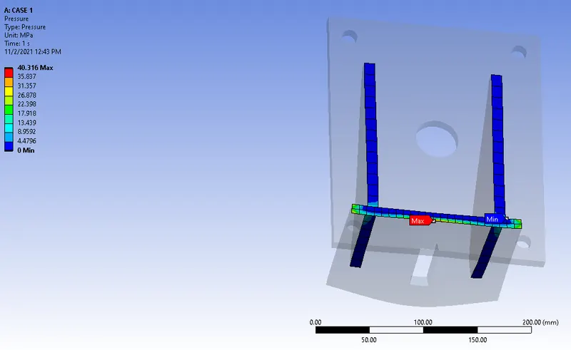
The contact tool of the status is max. and min. shown below.
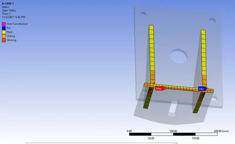
The max. and min. pressure points are 40.316MPa and 0 respectively.
Check for the safety factor of welding needs to be checked.
FOS= yield strength / maximum stress
= 250/304.01
= 0.8
FOS= Ultimate strength / maximum stress
= 460/304.01
= 1.51
In this case for FOS of yield strength will be less than 1, weld material will fail.
For ultimate strength will be more than 1 it shows the after the ultimate point the material gets into the fracture.
Case 2
Select the material of structural steel for both plates and aluminum alloy is for ribs, weld joints as shown below.
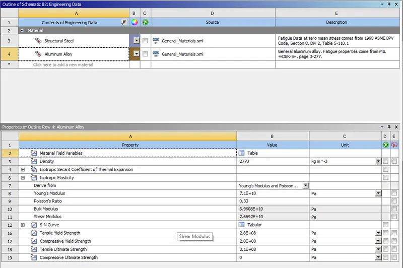
Accept the plates, select all models to select, and assign the material as the aluminum alloy is shown below.
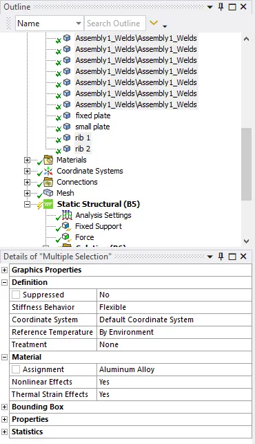
For plates select the material as structural steel and assign all analysis settings, fixed support, and force as shown below.
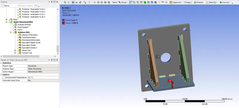
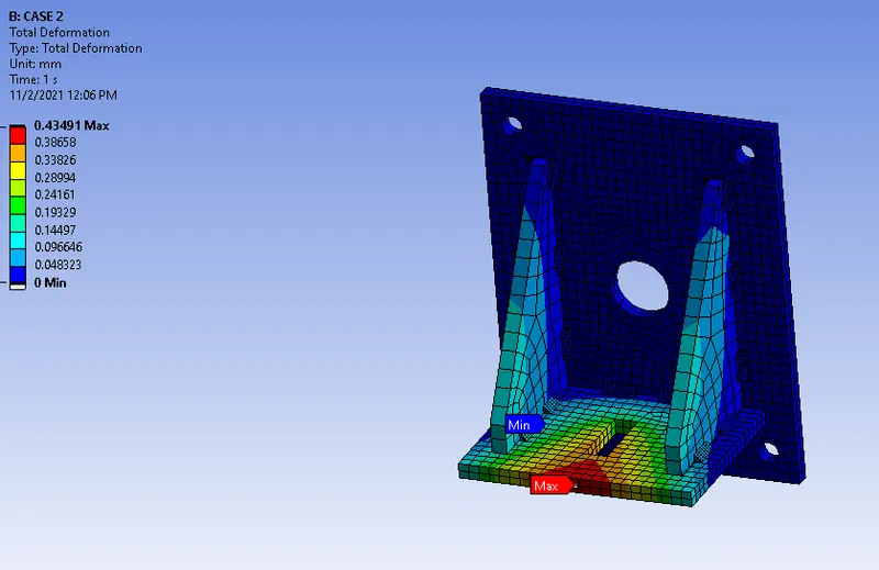
The below shows the total deformation of welded joints of plates max. 0.4349mm and min. 0 has been recorded as shown below.
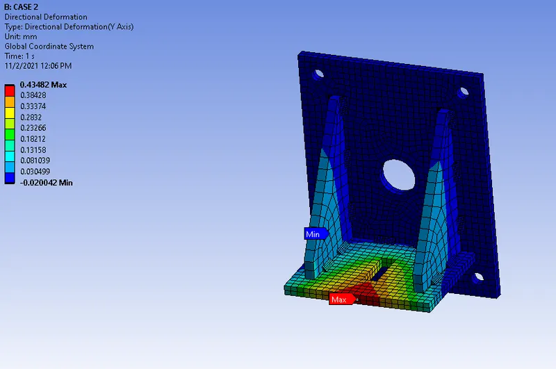
The directional deformation in Y-axis has been max. of 0.43482 and min. of -0.020042 as shown below.
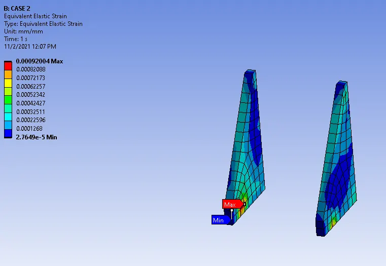
The below shows the max. strain for the ribs has been found 0.00092003 min. of 2.7638e-5.
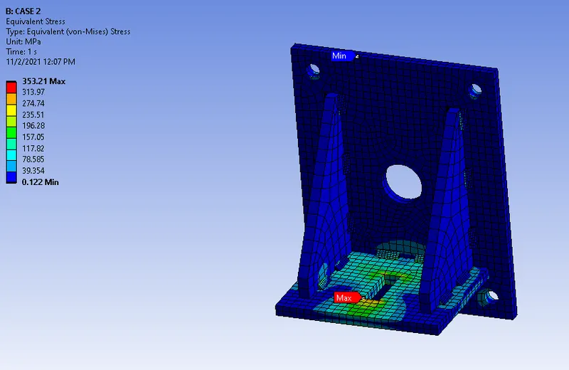
The equivalent stress is getting from force has been applied at the center it was showing the max. 353.21MPa and min 0.12198MPa as shown below.
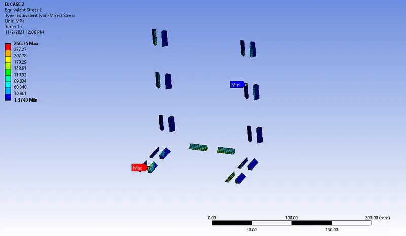
The equivalent stress of the welding joints has been shown the max. is 266.7MPa and min. of 1.3734MPa as shown below.
Stress tool
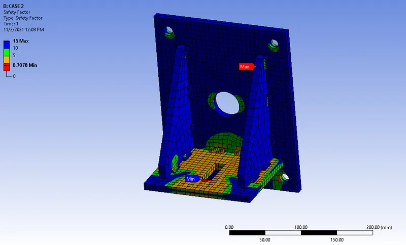
The stress tool has been more safety factor on ribs as shown in below min is of 0.7078 at the point load has been applying.
Contact tool
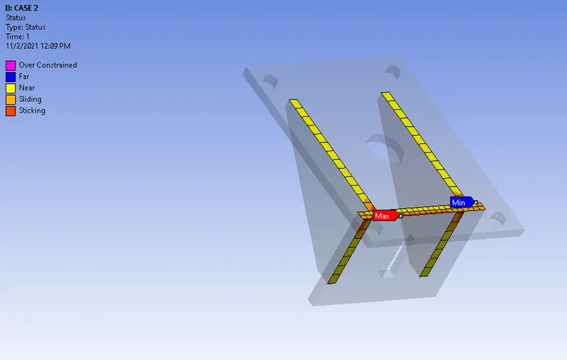
The status of the contact tool of max. and min as shown below.
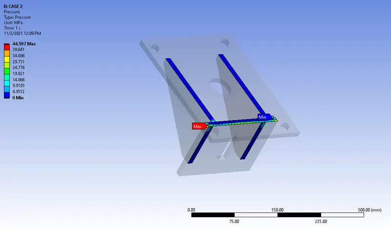
The contact tool of pressure max. of the 44.597MPa and min. at 0 as shown below.
Check for the safety factor of welding needs to be checked.
FOS= yield strength / maximum stress
= 363/266.7
= 1.36
In this case for FOS of yield strength will be less than 1, weld material will fail.
Case 3
Similarly used all process as same as done with above only change with material assigning in the components.
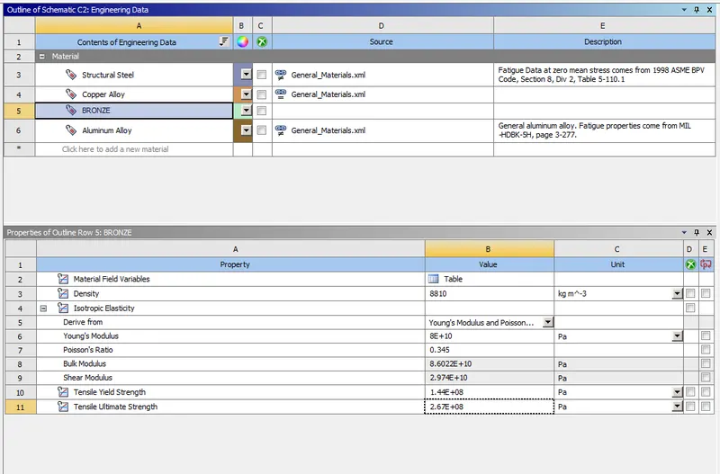
In this case the specifically bronze is used for welding material. stainless steel for plates and copper are used for both ribs as shown below.
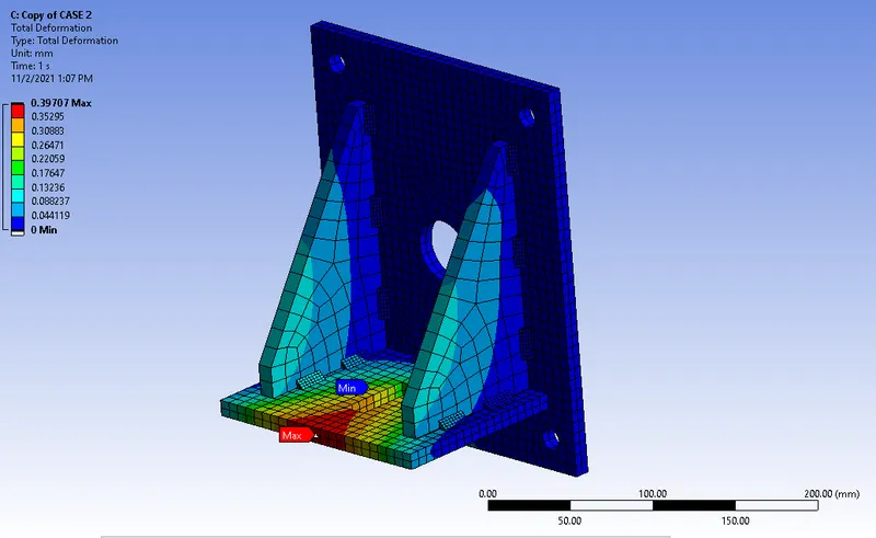
After plotting the all results for the component after solving the total deformation of the bracket is as shown below.
The max. of total deformation is 0.39707mm and the min. of 0.
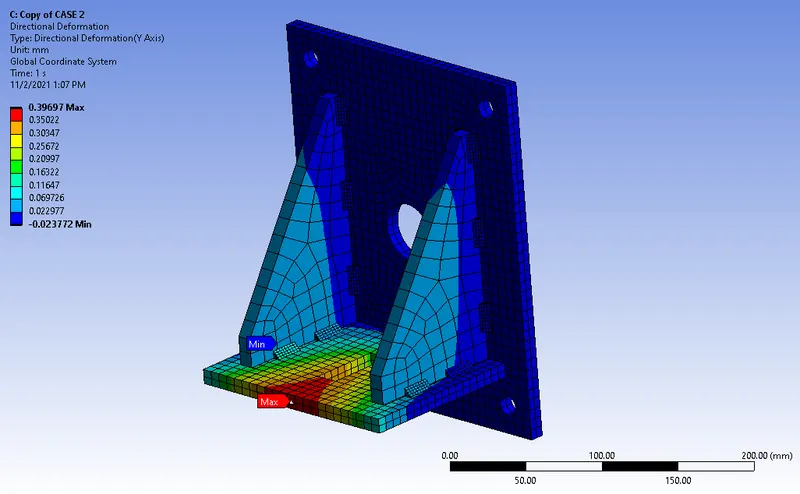
The directional deformation of the welding joints with plates with ribs is shown below.
The max. of directional deformation will show 0.39697mm and the min. has -0.023772mm.
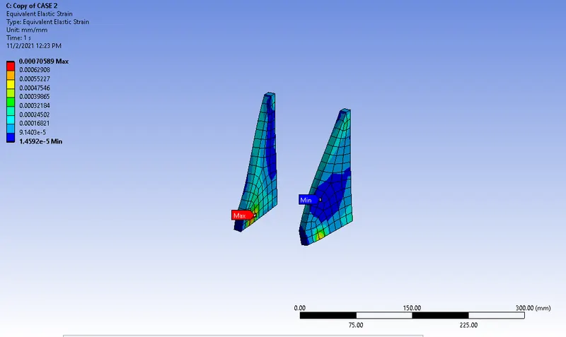
The below shows the max. strain for the ribs has been found 0.00070589mm min. of 1.4592e-5mm.
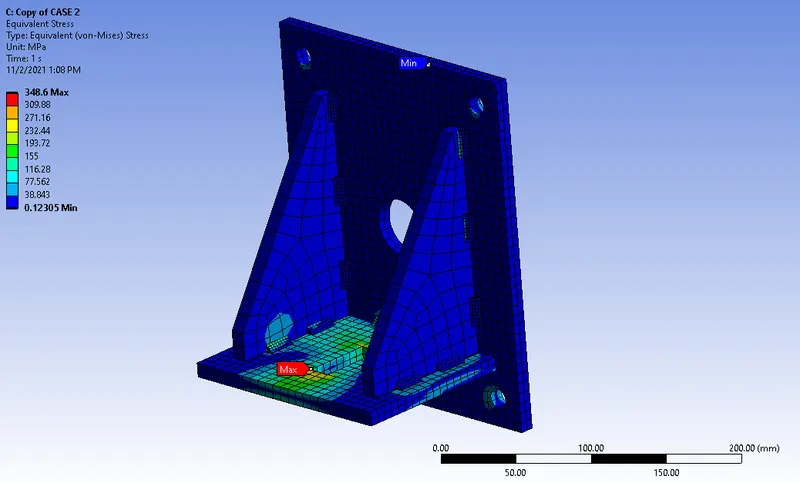
The equivalent stress is getting from force has been applied at the center it was showing the max. 348.6MPa and min 0.12305MPa as shown below.
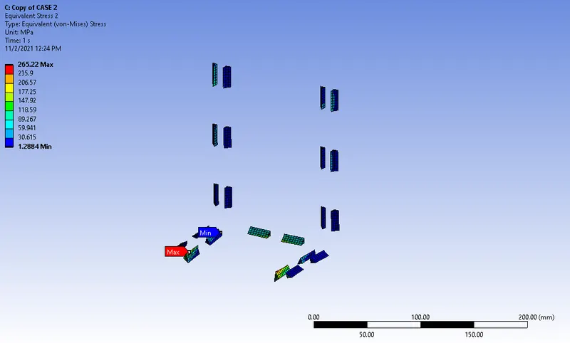
The equivalent stress of the welding joints has been shown the max. is 265.18MPa and the min. of 1.2895MPa as shown below.
Stress tool
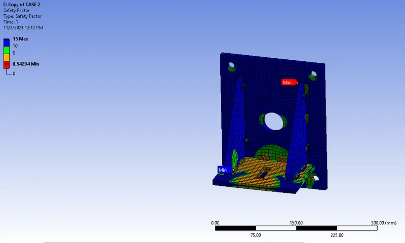
The stress tool has been more safety factor on ribs as shown in below min is of 0.54294 at the point load has been applying.
Contact tool
The status of the contact tool of max. and min as shown below.
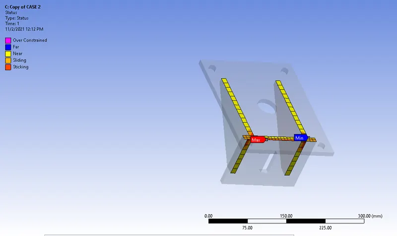
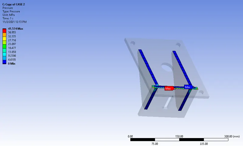
The contact tool of pressure max. of the 41.573MPa and min. at 0 as shown below.
Check for the safety factor of welding needs to be checked.
FOS= yield strength / maximum stress
= 144/265.18
= 0.54
FOS= ultimate strength / maximum stress
= 267/265.18
= 1.006
In this case for FOS of yield strength will be less than 1, weld material will fail.
For ultimate strength will be more than 1 it shows the after the ultimate point the material undergoes the fracture.
Results
Results are plotted in the below-tabulated column.
| Directional deformation in mm | Directional deformation in mm(Y-axis) | Equivalent strain(mm) | Equivalent stress |
Equivalent stress 2 (weld joints) |
FOS(welding joints) | Safety factor | Pressure point | |
|
Case 1 (Structural steel ) |
0.34027 | 0.34015 | 0.00048934 | 337.02MPa | 304.01MPa | 0.8 | 0.7418 | 40.316MPa |
|
Case 2 (Copper alloy) |
0.4349 | 0.43482 | 0.00092003 | 353.21MPa | 266.7MPa | 1.36 | 0.7078 | 44.597MPa |
|
Case 3 (Bronze) |
0.39707 | 0.39697 | 0.00070588 | 348.6MPa | 265.18MPa | 0.54 | 0.5429 | 41.573MPa |
The max. of 0.4349mm in case 2 deformations for the welding component has to compare with case 1 and case 3.
Compering with the 3 cases max. directional deformation in Y-direction has been more in case 2 of 0.43482 compering with other results.
For equivalent strain is the max for case 2 shown 0.00092003 because of materials selected for welding to plates and ribs compared with case1 and case 2.
The pressure point will be more in case 2(aluminum alloy)of 44.597MPa
By comparing the safety factor with the yield strength of the weld material will be stable/safe for the aluminum alloy and it is having the FOS will be showing 1.36.
Conclusion
By doing this static structural analysis for the welding joints in the given model with different types of filler material. To understand the FOS with suitable weld materials.