Assignment 2-RADIOSS Engine File Editing & 3D Meshing Challenge
- Component 1
Aim- Create a Teramesh for Housing component with the following quality criteria and 2D to 3D tetra mesh Conversion for given condition.
Procedure- Import the step file from the folder
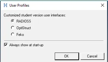
select the user profile as optistruct for the component.
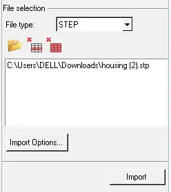
Import the geometry from file selection and its in step and select that and import.
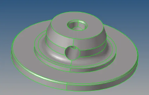
Import the component its in to GUI.
For this component do the 2D mesh as per the given condition.

mension the target element size is 5 and select the mesh type as trias. select the surface and mesh the given component
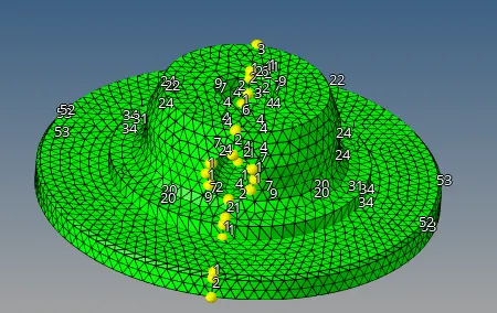
Accept the mesh and check for the min and max. element length.
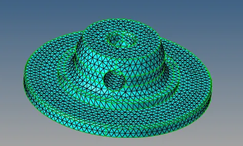
Next create it for 3D mesh to the same component.
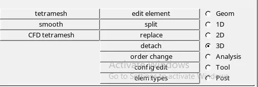
Select the 3D from tool bar and select the tetramesh. select the all 2D elements and 3D mesh for the component.

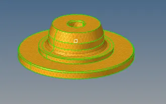
The 3D tetra mesh has been done for the below component.
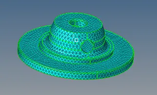
Check for the tet collapse for the component.

The tet collapse shows 0% for failing the elements to component.

To check the 3D elements mask the the elements

select some region and it shows the 3D elements and select unmask all as shown in below.
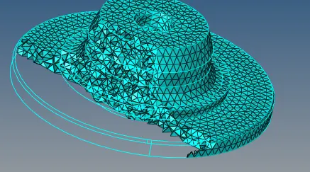
The final component is as shown below.
Conclusion
As per the given condition the component is ready with the tetra mesh.
- Component 2
Aim- Create a Teramesh for Housing component with the following quality criteria and 2D to 3D Conversion for given condition.
Procedure- Import the step file from the folder
select the user profile as radioss for the component.
Import the geometry from file selection and its in step and select that and import.
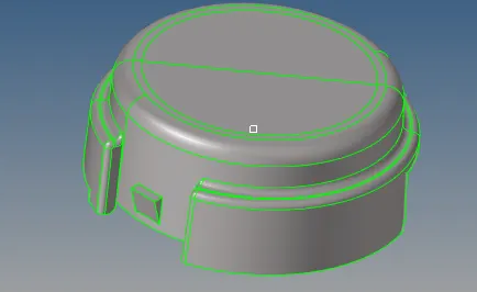
The below shown the import model.
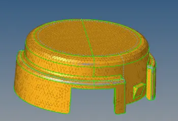
For this component do the 2D mesh as per the given condition.
Mension the target element size is 5 and select the mesh type as trias. select the surface and mesh the given component
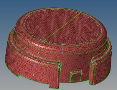
Next create the 3D mesh for the component.
Select the 3D from tool bar and select the tetramesh. select the all 2D elements and 3D mesh for the component.
The 3D tetra mesh has been done for the below component.
Below showing image the check the elements are failing for tet collapse .
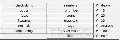
Select the check elements.

To check the 3D elements mask the the elements

Already saved elements can be visible by selecting the retrive, mask and reverse.

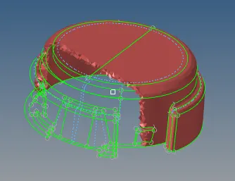
The elements are seems to below shown in fig.
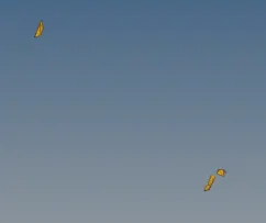
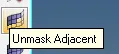
Choose the option and select it for the unmask adjecent for the component.
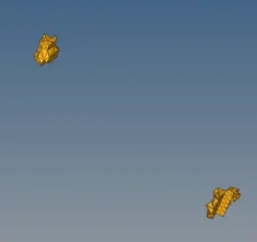
The neibour 3D elements can bounded as below shown.
Again select the tetramesh option and use the tetra remeshable
The select the all 3D elements create the remesh for the same.

Now its check it for the tet collapse and it shows the how many elements are failing for the tet collapse.

The below shown the elements for failing.

Repete the same procedure for this and make its 0% of failing as shown in below.

select some region and it shows the 3D elements and select unmask all as shown in below.
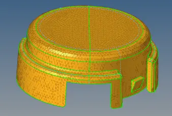
The final component is as shown below.
Conclusion
As per the given condition the component is ready with the tetra mesh.
- Component 3
Aim- Create a Teramesh for Housing component with the following quality criteria 3D hexa mesh Conversion for given condition.
Procedure- Import the step file from the folder
select the user profile as optistruct for the component.
Import the geometry from file selection and its in step and select that and import.
Import the component its in to GUI.
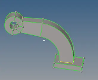
The component consisting of 4 separate component as shown in below.
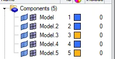
For given components primarly delete the solid part of the component

Now the select the component by one by one
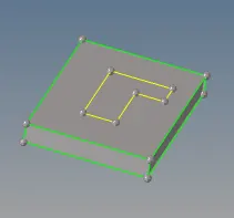
For meshing target element size should be 10 as per the data.

The 2Dmesh can be crate on the face of component as shown in below.
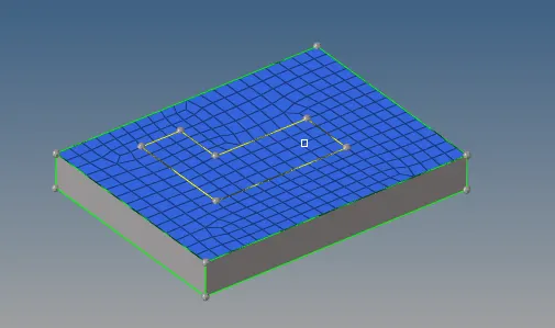

By selecting the ele offset option choose the slid layers and assign the parameters for the no. of layers for the total thickness.

Select for the 2 adjecent faces and select the offset option.
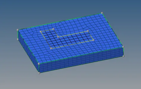
Mask the 3D hexa elements and leave the 2D elements to project ferther.

The given 2D component is as below shown.
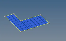
For the arm component create the 3D hexa elements for the component.
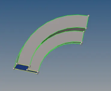
For this arm create the center of arc by placing the node.

To crate the 3D hexa elements by using the spin option
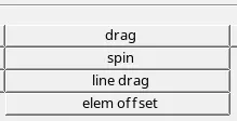
Select the option by spin elements and select the 2D elements and choose the axis with the base point. Spin the component

The component is shown as shown in below.
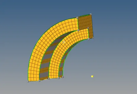
For extended component have to make the 2D mesh for the surface and create the 2D mesh.
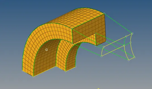
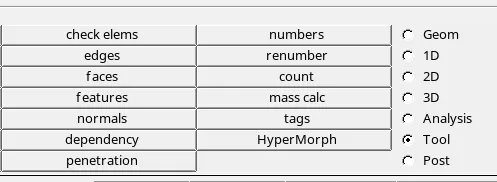
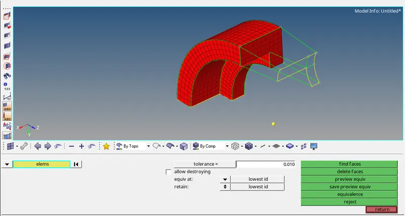
For tools slect the check elements for the arm component
The 2D mesh face will be appeared
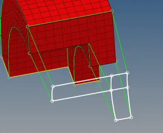
Select the 2D mesh for the front surface and match the elements are in lever as shown in below.

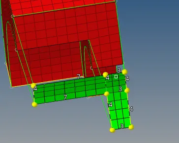
By using the linear solid option the drag the hexa elements for the component.

In this component choose the from elements to elements and select the exact node from the both mesh faces and give the density for the component.
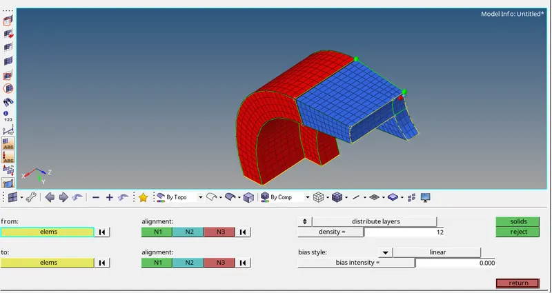
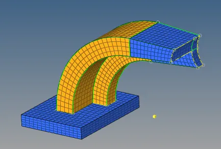
The given component as shown in below.
The another component is the bush can be create the 2D mesh on the side of the bush.
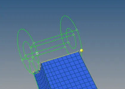
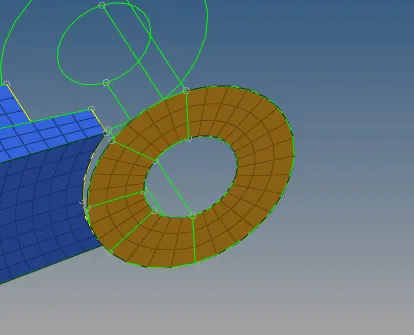
Project the node from the elements by duplicatin the node and the projrct in to the edge as shown in below.

Using the solid map for the component create the hexa mesh for the component.
In solid mapping select the general source geom as none, destination geo select, slect the elements to drag, along geometry as the mixed(select the line, surface and node path) along the parameter as 10 and mesh it

Below shown the hexameshing has been generated for bush component.
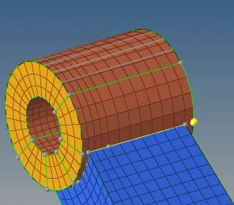
Delete the 2D elements can be createdand delete the entity.

The finally bush is seems to be below shown.
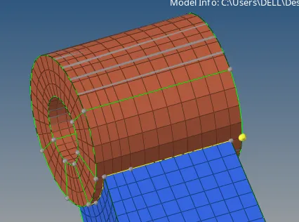 \
\
The 4 components for the hexamesh is as shown in below.
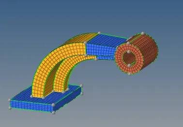
Conclusion
The given component how to create the hexa meshing for the component by using the various options for hexa.
- Analysis 1
Aim-To perform the analysis for given parameters and calculate the values for starter file and assign the values in engine file to run.
Procedure -
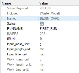
Check for the BEGIN CARD file as shown in below for the unit conversions.
Select the material to know the material property.
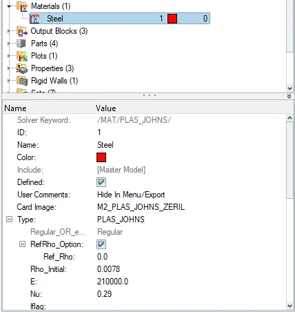
1) Calculating the speed of sound (C)= `root`E/`rho`
= `root`210000/0.00789
=`root`26923076.923
= 5188.74 ms
2) Length of rail=tc=l/C
= 1000/5188.74
=0.1927 ms
3)Time for sound to travel length of rail= 0.1927 ms
4) stress wave can be monitored, moving from one end of the rail to the other during impact -this will require a termination
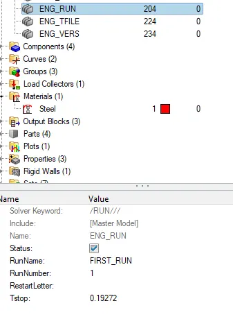
time equal to the time it takes for the sound to travel the length of the rail= 0.19272 ms.
Put this values in ENG_RUN file.
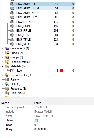
5) Set the values for the animation for 20 animation steps =Tq=0.19272 / 20 = 0.009636
set this values in ANIM_DT file.
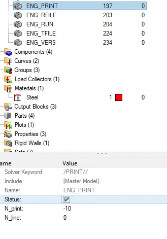
6) Change /print as setted -10
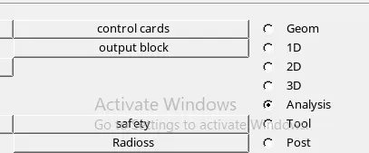
Analysis can be set by selecting the Radioss.
Select the input file and set new folder name without any space.

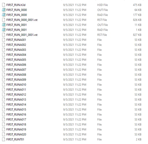
The final 20 animation steps will created the file as shown in below.
Conclusion
By doing this analysis to know the elemental time step and how to assign in run the engine file by using radioss solver.