Week 11 Car Crash simulation
Aim- To determine the analysis of the explicit dynamics for the given car crash model.
Objectives
- To perform a parametric study using 3 different values of thickness for the car body.
- To apply the same conditions as mentioned in the video that corresponds to this challenge. Analyze the total deformation and Equivalent stresses acting on the model.
Introduction
Over the last decade, crash test regulations have become more stringent, requiring a higher level of performance to achieve a good safety rating. For example, test speeds have been increased, and traditional automotive models were unable to handle this large amount of crash energy which lead to the collapse of the survival space and poor safety ratings. OEMs needed to increase the study of the structure, materials, and restraint systems in order to achieve five-star ratings again and this is where crashworthiness simulation plays a vital role.
High performance and high fuel economy are the two contradictory targets that push the automotive structure to the limit of lightweight robust architecture. The arrival of newer vehicle platforms for electric, connected, and autonomous vehicles have shortened product design cycles. As regulations and OEM in-house safety targets tighten, the demand for crash simulations is increasing exponentially. There are many technical challenges in achieving the best crash safety ratings and getting regulatory approvals and high fidelity and accurate simulations are essential to obtaining an optimized solution.
Procedure
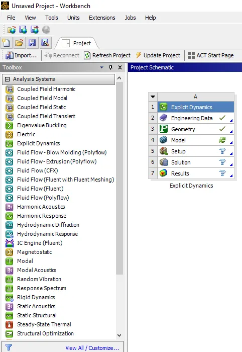
To open the toolbar and apply the explicit dynamics as shown below.
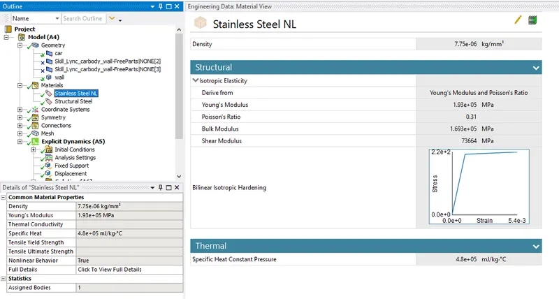
The material has to be the stainless steel NL as shown below.
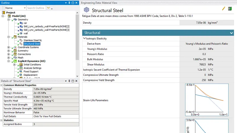
The material has to be stainless steel as shown below.
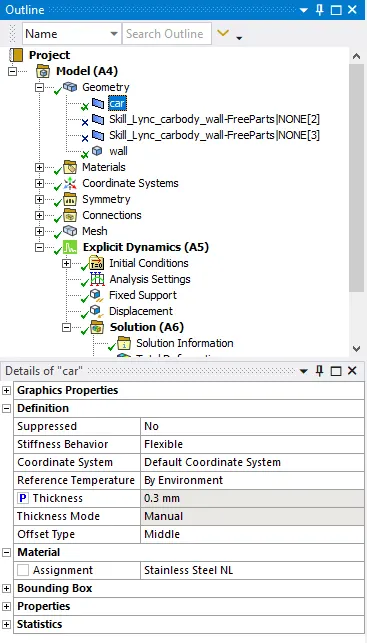
Assign the car geometry as stainless steel NL select the parameter settings of the car as shown below.
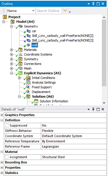
Similarly, for the wall select the structural steel as shown below.
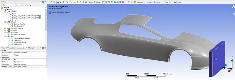
Select the wall for the paich confirming method and select the body and select the tetrahedron elements.
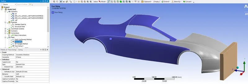
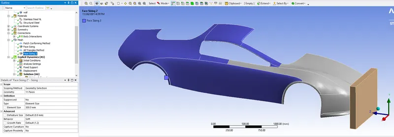
Do the face sizing with the element sizing of 200mm a shown the selected face.
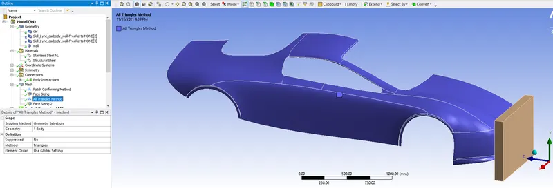
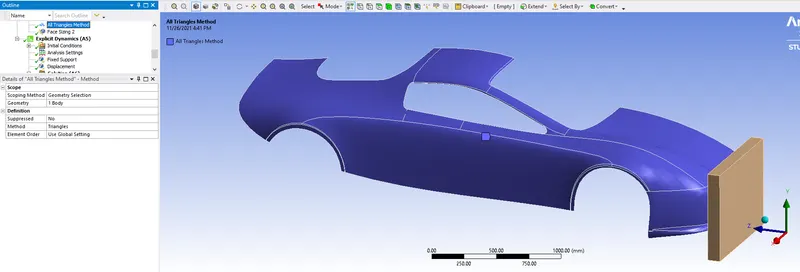
All tringle methods select the car component as shown below.
If facing any error do the face sizing for the selected areas 300mm as shown below.
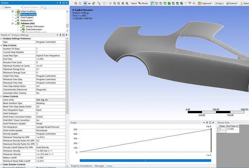
Do the analysis settings as shown below the car has been shown.
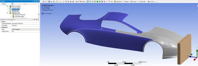
Select the fixed surfaces as shown below select type will be the fixed support.
The displacement has to be given for the wall as shown below.
After the simulation the plot all animation results as shown below.
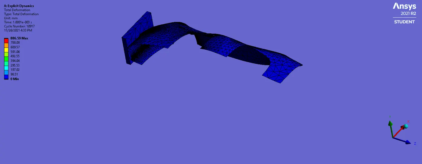
The total deformation has to be found at 886.59mm as shown below.
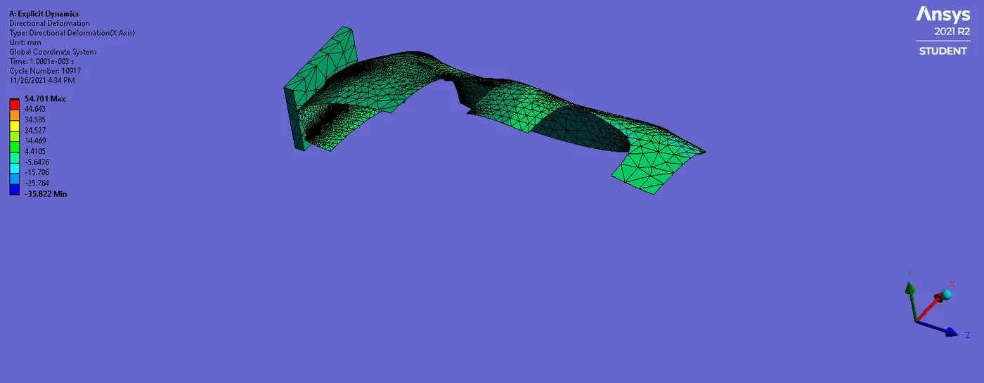
The directional deformation is found to be in X-axis is max. at 54.701 mm and -35.822mm as shown below.
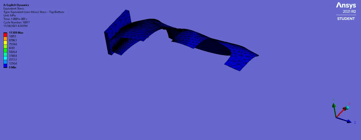
The equivalent stress for the given car crash will be max. of 11309 MPa as shown below.
Similarly, for the other cases, we can run the simulation by assigning the various thickness for the component as shown below.
Results
With the varying parametric thickness of 0.4 and 0.5, the car crash shows all tabulated results will be as shown below.

Also for equivalent stress and elastic strain will be shown below.

Conclusion
- The total deformation will be found max for the parametric thickness of 0.3 mm will give the 886.59mm and min will be the parametric thickness of 0.5 mm gives -34.975 mm as shown below.
- The directional deformation max for the thick of 0.3mm gives 54.701 and the min. is of 0.5 mm thick gives the 53.778mm as shown above table.
- The equivalent stress will be max. at the parametric thickness of 0.3mm gives the 7014.1MPa and min. of the parametric thickness of 0.5mm gives 6988.1MPa as shown above table.
https://drive.google.com/file/d/1CPqG6kfTAi7LaVcG-sacsfyqI7D7PDXw/view?usp=sharing