Week 3 Sheet metal Bending challenge
Aim- To perform the static structural for the given sheet metal bending.
Objectives
The given welding model does the preprocessing, solver, postprocessing.
Case 1. Solve by using sheets as Aluminum alloy 1199, Copper alloy, and magnesium alloy.
Case 2. Solve by using aluminum alloy with a friction coefficient of 0.19 has sheet material.
Case 3. Solve by using aluminum alloy and use the refine mesh size.
Introduction
Sheet metal bending is an operation that involves using forces to change the shape of a sheet. This is done to achieve the desired form or shape needed for a manufacturing process. The external force used alters only the external features of the sheet.
Types
There are three basic types of bending on a press brake, each is defined by the relationship of the end tool position to the thickness of the material. These three are Air Bending, Bottoming, and Coining. The configuration of the tools for these three types of bending are nearly identical. A die with a long rail form tool with a radiused tip that locates the inside profile of the bend is called a punch. Punches are usually attached to the ram of the machine by clamps and move to produce the bending force. A die with a long rail form tool that has a concave or V-shaped lengthwise channel that locates the outside profile of the form is called a die. Dies are usually stationary and located under the material on the bed of the machine. Note that some locations do not differentiate between the two different kinds of dies (punches and dies). The other types of bending listed use specially designed tools or machines to perform the work.
Procedure- To start the simulation by opening with the Ansys workbench.
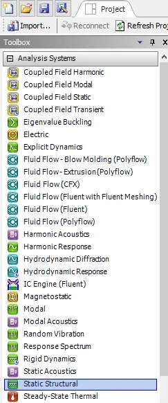
Select the static structure from the toolbox as shown below shown.
In static structural select to assign the material property in engineering data.
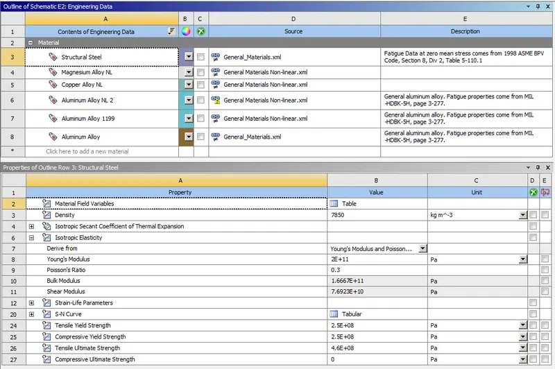
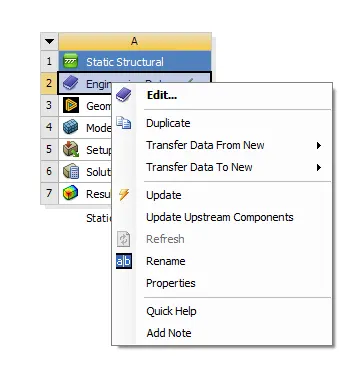
Update the engineering data as shown below.
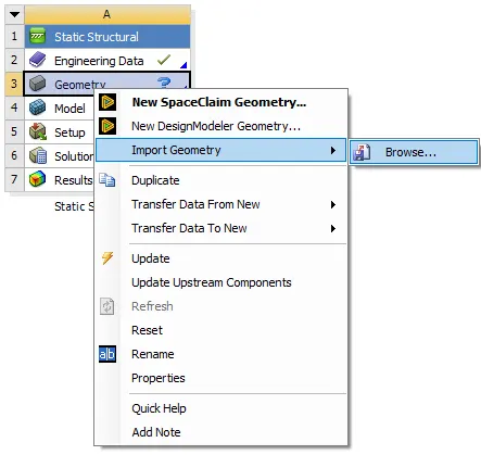
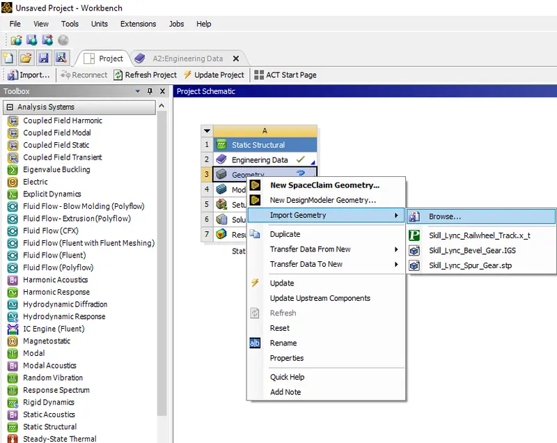
Also import the geometry from the browse with the updated geometry.
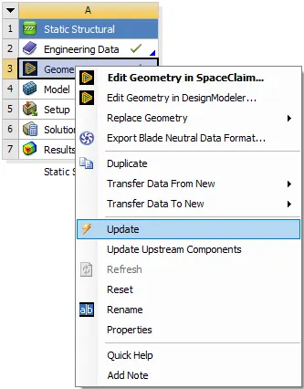
After updating the geometry double click on the model, its popup with the model window.
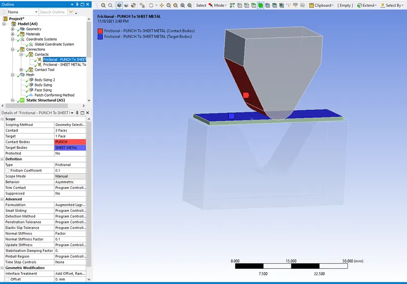
Create the contact for the contact bodies punch and target bodies.
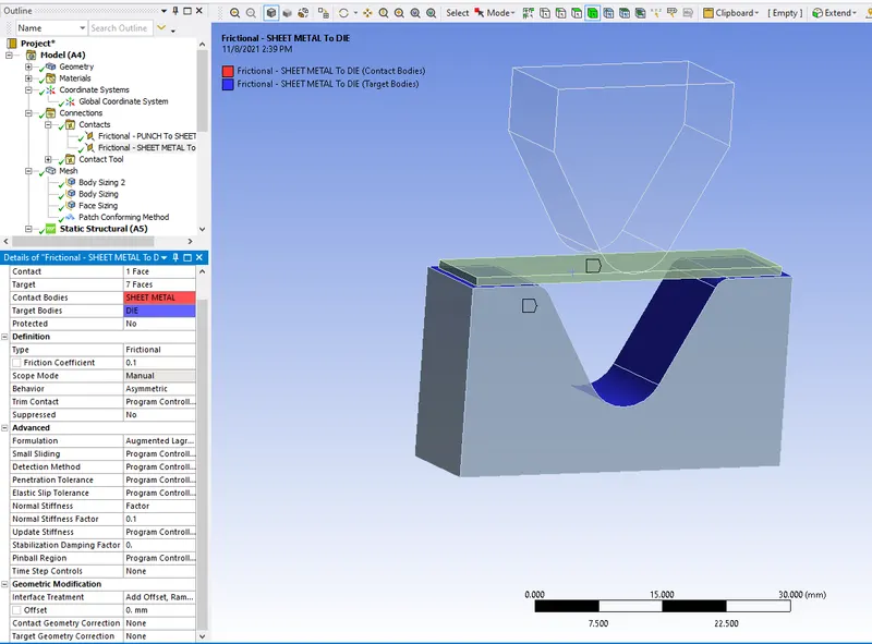
Select both contacts as the frictional as shown below.
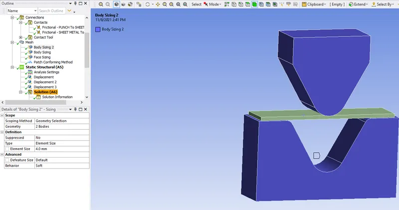
Meshing by selecting the body sizing by selecting the face of punch and die as 4mm shown below.
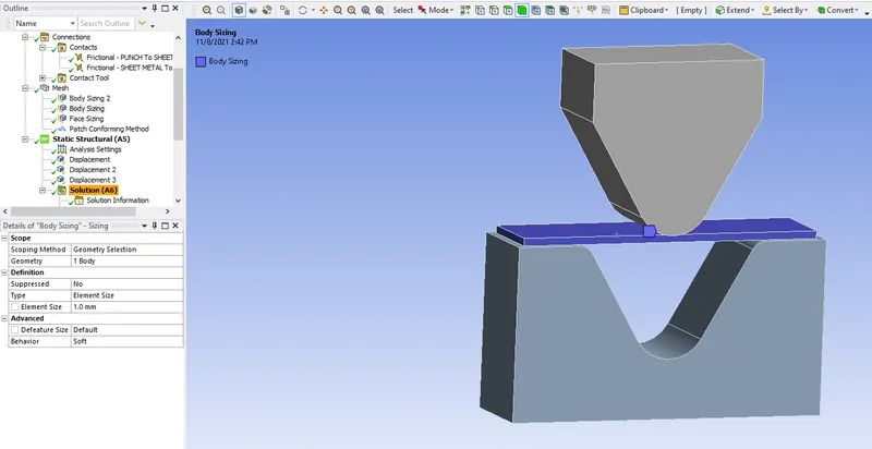
Select the mesh sizing for the sheet as 1mm shown below.
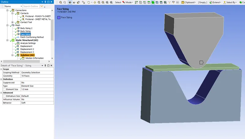
Select the mesh sizing of the punch and die faces as 1mm shown below.
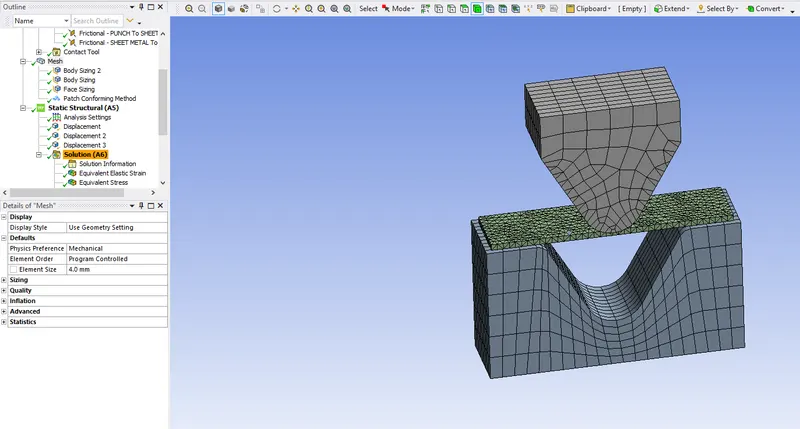
After generating mesh it's showing as shown below.
Set with the analysis settings as shown below.
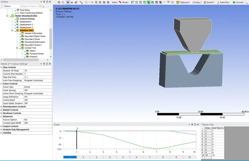
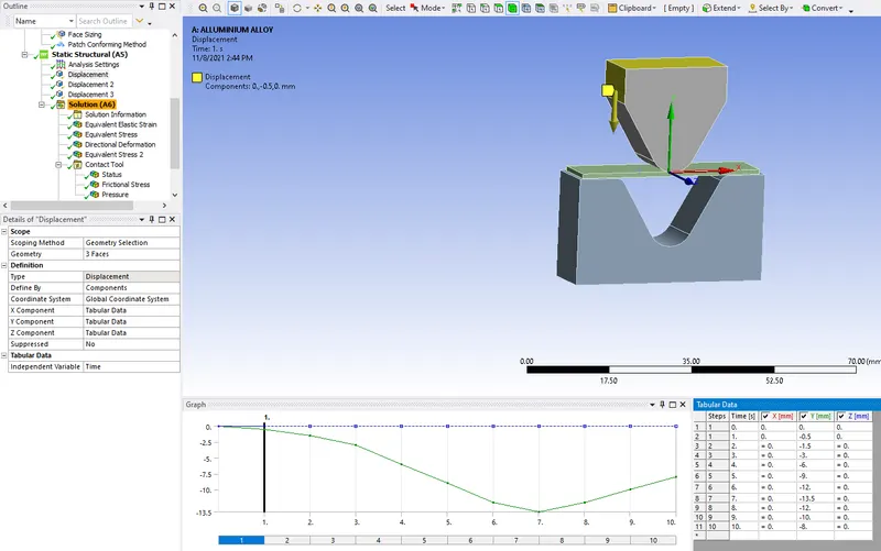
Create the displacement for the component and select all punches of the face shown and also mention the time steps to the displacement.
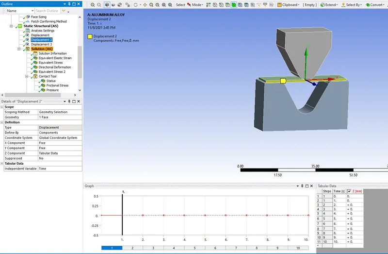
Select the displacement of the workpiece for the workpiece as shown below.
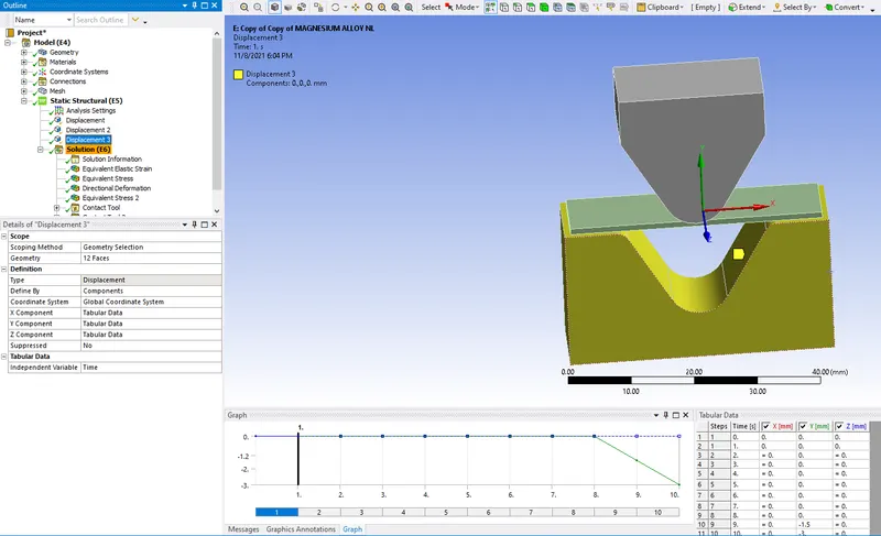
Displacement for the die and select all faces as shown below.
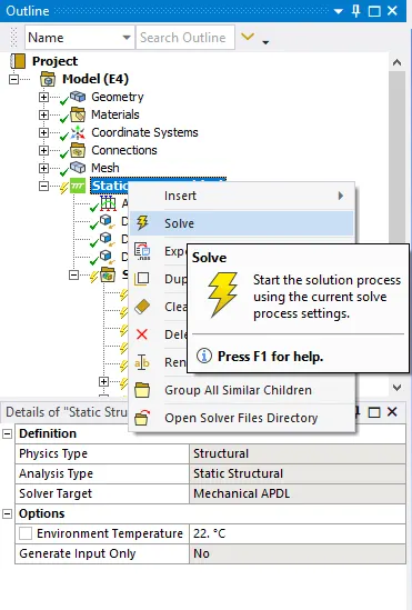
Solve the static structure and solve the simulation.
Aluminum alloy 1199
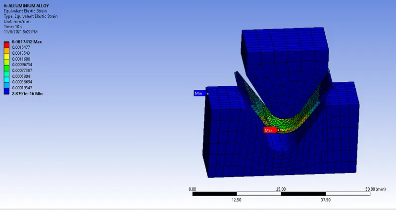
The elastic strain of the solution is shown below
Max. 0.0017412mm and min 2.8791e-16mm.
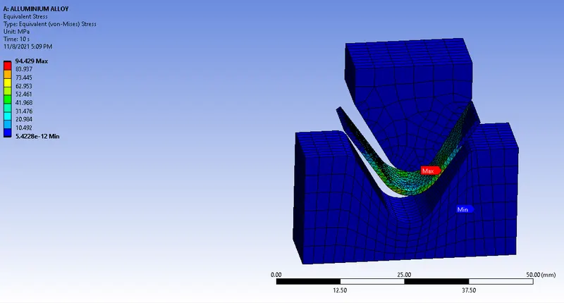
The elastic stress of the solution is shown below
Max. 94.429MPa and min 5.4725e-12MPa.
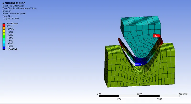
The directional deformation of the solution is shown below.
Max. 2.4159mm and min -12.668mm.
Similarly for selecting other materials as per the given statement maintain the same procedure for the above shown.
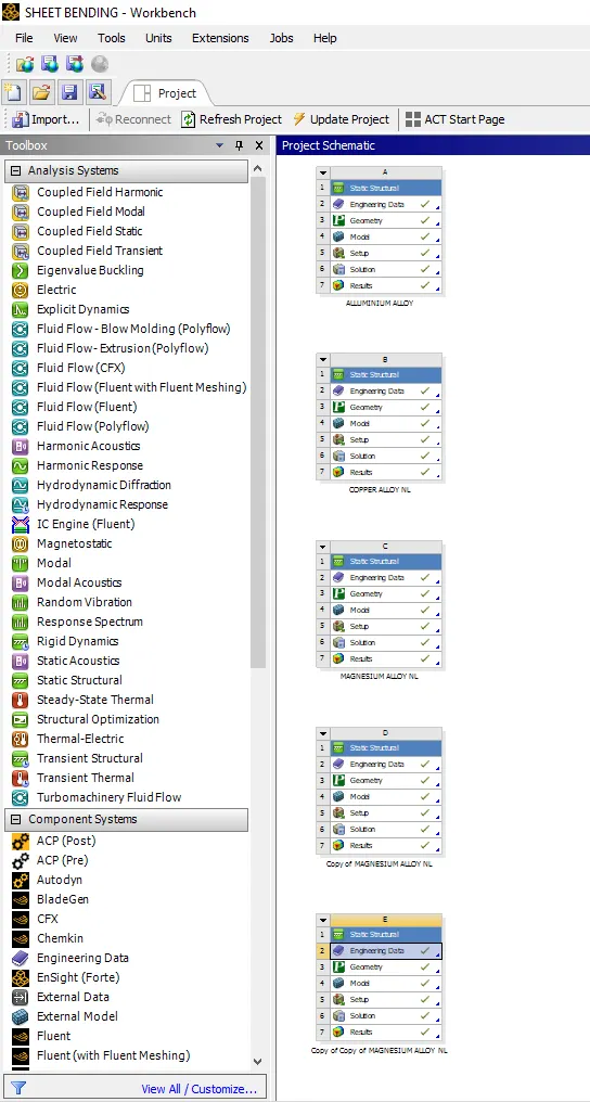
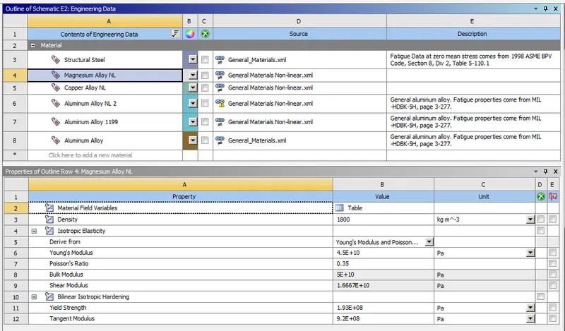
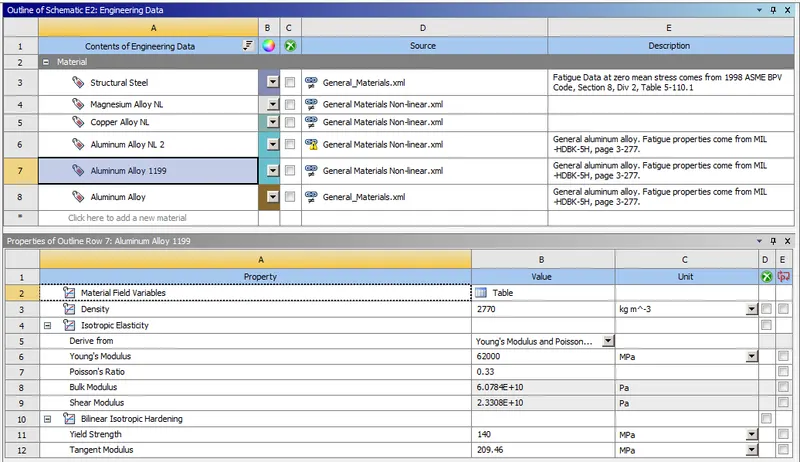
The magnesium alloy, aluminum alloy 1199, Aluminium alloy NL, and copper alloy as shown in the below property.
Aluminum alloy NL
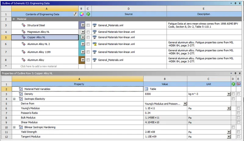
Aluminum alloy 1199
Aluminum alloy
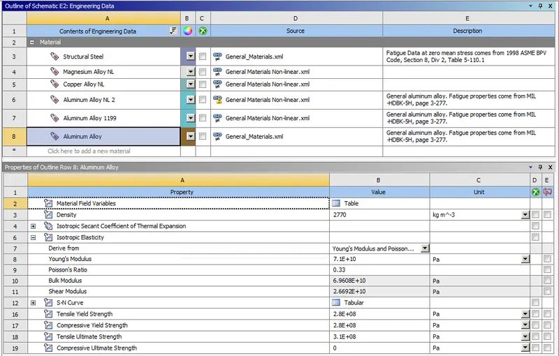
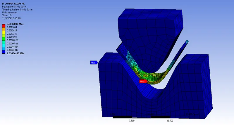
By using the material as Copper Alloy NL after solving the solution for the stress, strain, and total deformation as shown below.
The elastic strain of the solution is shown below
Max. 0.0019838mm and min 2.5306e-16mm.
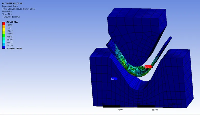
The elastic stress of the solution is shown below
Max. 294.56MPa and min 2.5834e-12MPa.
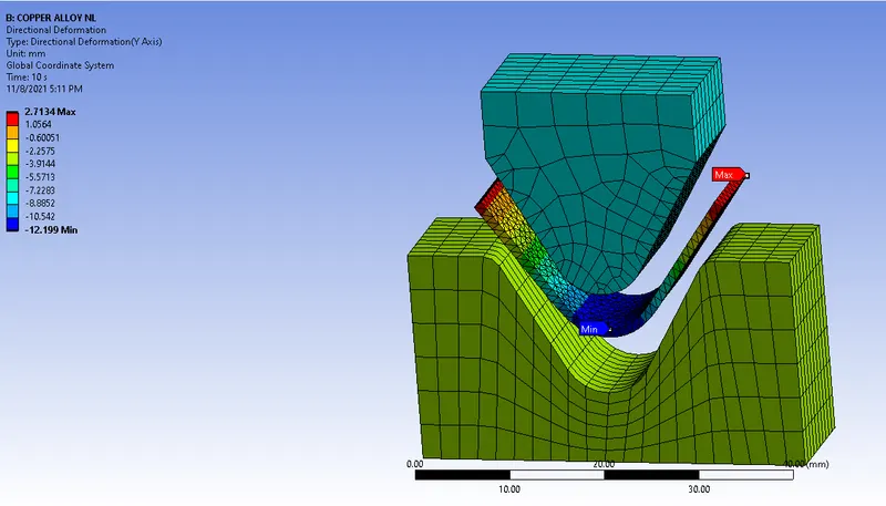
The directional deformation of the solution is shown below.
Max. 2.7134mm and min -12.199mm.
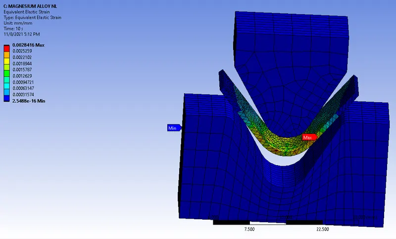
Magnesium Alloy NL
The elastic strain of the solution is shown below
Max. 0.0028416mm and min 2.5488e-16mm
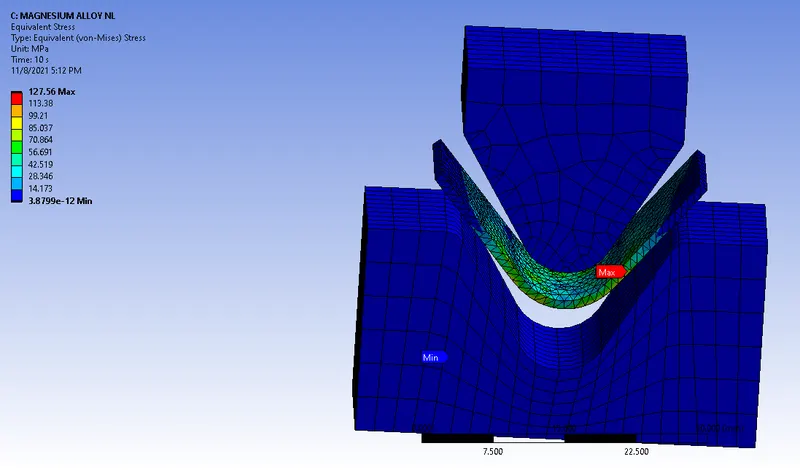
The elastic stress of the solution is shown below
Max. 127.56MPa and min 3.8799e-12MPa.
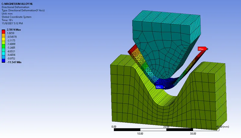
The directional deformation of the solution is shown below.
Max. 2.5974mm and min -11.547mm.
The tabulated all results for case 1 as shown below.
| Elastic Strain | Stress | Directional deformation | |
| Aluminum alloy 1199 | 0.0017412mm | 94.429MPa | 2.4159mm |
| Copper Alloy NL | 0.0019838mm | 294.56MPa | 2.7134mm |
| Magnesium Alloy NL | 0.0028416mm | 127.56MPa | 2.5974mm |
Compering with elastic strain is more in magnesium alloy NL compering with other results.
For stress and directional deformation is more in copper alloy NL of 294.56MPa and 2.7134mm respectively compering with other material results.
Case 2
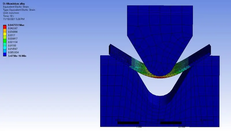
Aluminium Alloy
The elastic strain of the solution is shown below.
Max. 0.047551mm and min 3.4758e-16mm
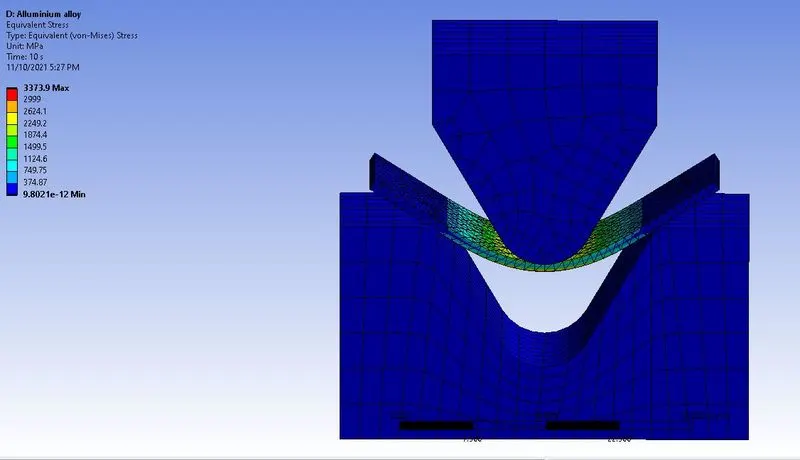
The equivalent stress of the solution is shown below.
Max. 3373.9MPa and min 9.8021e-12MPa.
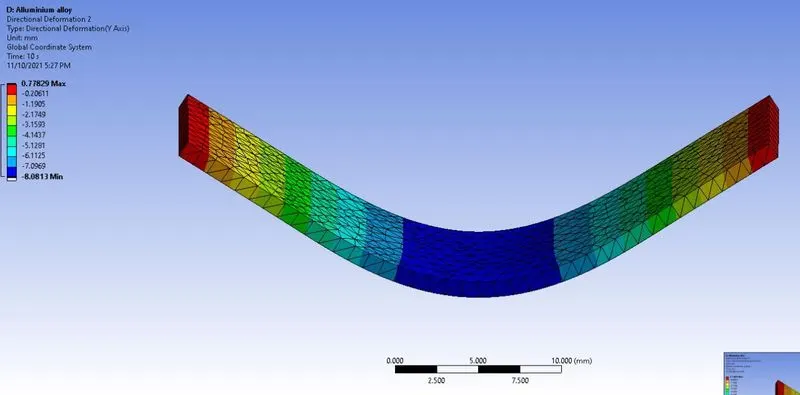
The directional deformation of the solution is shown below.
Max. 0.77829mm and min -8.0613mm.
The tabulated all results for case 1 as shown below.
| Elastic strain | Stress | Directional Deformation | |
| Aluminium Alloy with 0.19 friction coefficient | 0.047551mm | 3373.9MPa | 0.77791mm |
| Aluminum alloy 1199 | 0.0017412mm | 94.429MPa | 2.4159mm |
Compering with case 1 Aluminum alloy 1199 with Aluminium Alloy with 0.19 friction coefficient has been tabulated the above.
For elastic strain, the max strain occurs in aluminum alloy with 0.19 friction co-efficient compere with the aluminum alloy 1199.
For stress is more in aluminum alloy with 0.19 friction co-efficient compering with the aluminum alloy 1199
For the directional deformation for the aluminum alloy with 0.19 friction co-efficient is less compering with aluminum alloy 1199.
Case 2
Aluminium Alloy
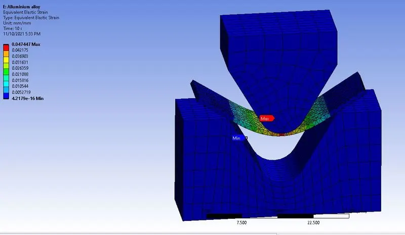
The elastic strain of the solution is shown below
Max. 0.047447mm and min 4.21798e-16mm
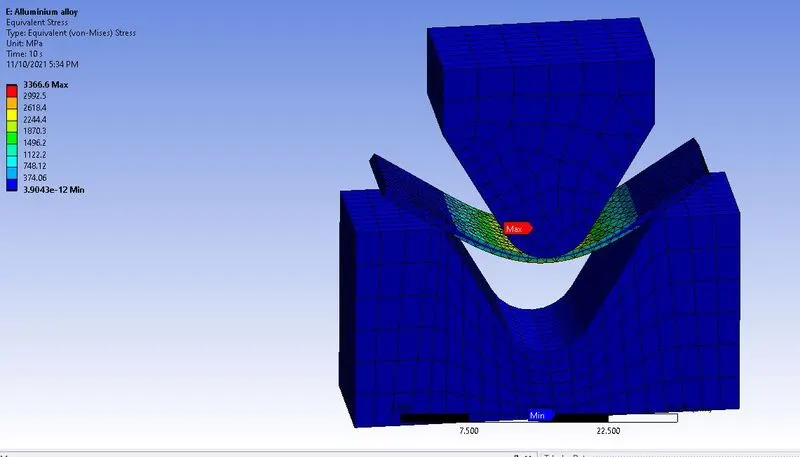
The equivalent stress of the solution is shown below
Max. 3366.6MPa and min 3.90431e-12MPa.
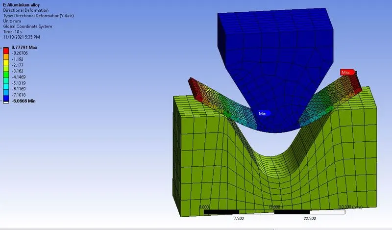
The directional deformation of the solution is shown below.
Max. 0.77791mm and min -8.0868mm.
Results
The tabulated all results for case 1 as shown below.
| Elastic strain | Stress | Directional Deformation | |
| Aluminium Alloy with 0.9mm | 0.047447mm | 3366.2MPa | 0.77791mm |
| Aluminum alloy 1199 | 0.0017412mm | 94.429MPa | 2.4159mm |
Comparing results
- For Deformation along the axis, Aluminium alloy with 0.9 mm mesh is deformed with a Maximum value of 0.77791 mm. The min will be the deformation
- Elastic strain, Maximum strain value is of Aluminium alloy with 0.9 mm mesh with the value of 0.047447mm. The strain will be more in aluminum alloy compared to aluminum alloy 1199.
- For Von mises stress, the Maximum stress value is 336.2MPa which is of Aluminium alloy with 0.9 mm mesh
Conclusion:
- For case 1, Deformation along Y axis, Magnesium NLalloy is deformed Maximum, for Elastic strain. The maximum strain value is of Magnesium alloy. For Von mises stress Maximum stress value is Copper NL.
- For case 2, Aluminium NLAlloy with Frie 0.19 is best in terms of deformation along. Strain and Stress.
- For case 3, Aluminium NL alloy with 0.9 mm mesh is best in terms of deformation along with Y, Strain, and Stress.
Google link
https://drive.google.com/file/d/1_ILHe6M7EIfLL8W9UarK18XdY_8-iYhG/view?usp=sharing