Week 8 Worm Gear Challenge
Aim- To determine the transient structural analysis for the given Worm Gear.
Objectives
- Introduction perform a transient structural analysis on a worm gear assembly
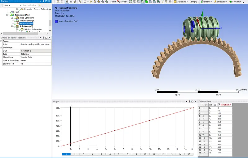
- you have to rotate the worm so as to get to almost the end of the half-cut and get results for Equivalent stress, Equivalent elastic strain, and the total deformation in the model.
Introduction
The worm and worm gear, which are illustrated in Figure 57.21, are used to transmit motion and power when a high-ratio speed reduction is required. They accommodate a wide range of speed ratios
Worm drives are used as the tuning mechanism for many musical instruments, including guitars, double basses, mandolins, bouzoukis, and many banjos (although most high-end banjos use planetary gears or friction pegs). A worm drive tuning device is called a machine head.
Materials for worm and worm gears are generally confined to steel for worms and bronze or cast iron for gears. When steel worms are run with bronze gears at high speeds, the worm is usually hardened with ground threads. There is often some confusion as to the self-locking ability of a worm and gear set.
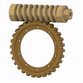
Worm gears are the most compact type of system and provide high-ratio speed reduction. They are often the preferred type of gearing system when space is limited and large gear reductions are needed. Worm gears can be used to either greatly increase torque or greatly reduce speed.
Procedure- To start the simulation by opening with the Ansys workbench.
Select the transient structure from the toolbox as shown below shown.
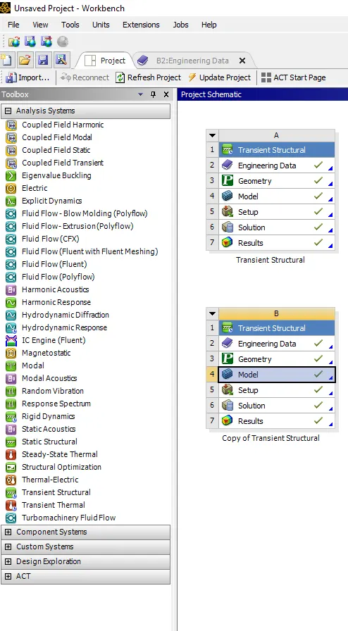
In transient structural selection to assign the material property in engineering data.
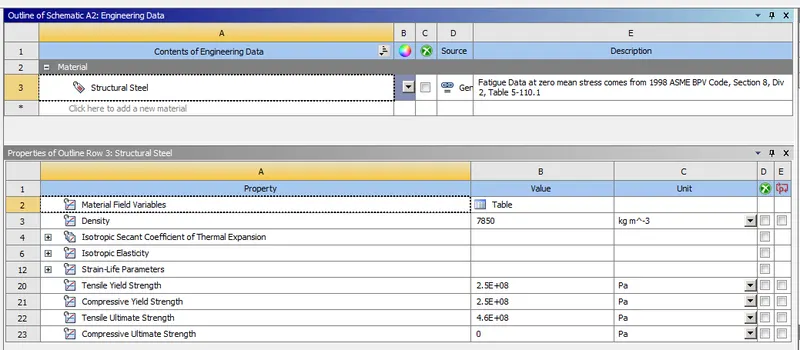
Update the engineering data as shown below.
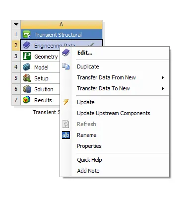
Also import the geometry from the browse with the updated geometry.
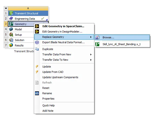
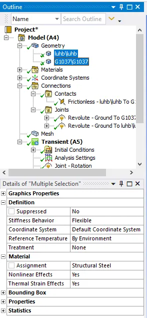
Import the geometry for the given model is of geometry and naming the component properly as shown. Select the material as the structural steel.
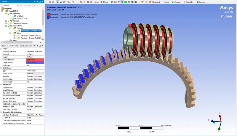
Create the frictionless contact for the given worm gear as shown below.
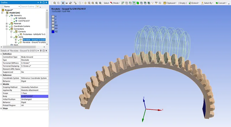
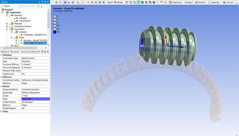
Create the revolute joints for the body to ground for the component as shown below.
Create the revolute joints for the worm as shown below.
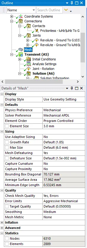
Generate the mesh for the given component a shown below.
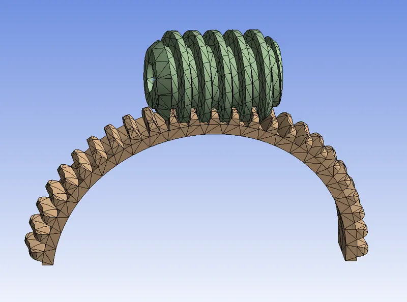
The below shown the component with meshing will be shown below.
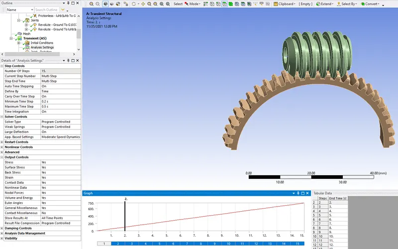
Do the necessary analysis settings for the model and set accordingly.
Create the joints for the given component and select the inside of the worm with the proper direction we can as shown below.
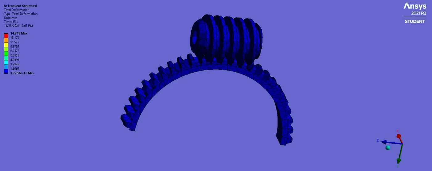
The total deformation of the component is the max. the value found at 14.818mm and min of 1.7764e-15mm is shown below.
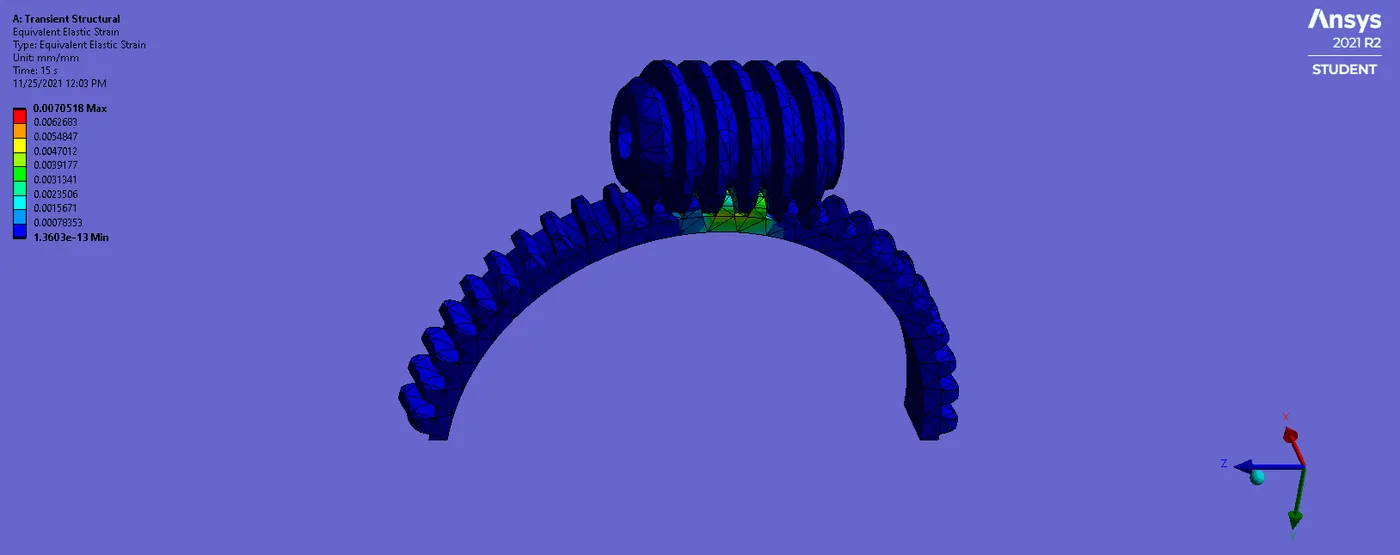
The equivalent elastic strain will be of max. of 0.0070518mm and the min of the 1.3603e-13mm as shown below.
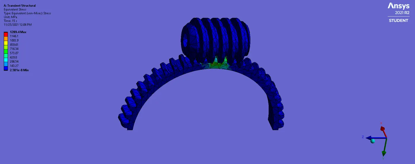
The equivalent stress of the given component will be 1289.4MPa and min of 2.581MPa as shown below.
Results
The results of the worm gear have been tabulated as shown in the below-shown table.
| Total Deformation | Elastic strain | Equivalent stress | |
| WORM GEAR | 14.818mm | 0.0070518mm | 1289.4MPa |
Conclusion
- The total deformation of worm gear was found to be max. of 14.818mm as shown in the table.
- The elastic strain will be found to be 0.0070518mm as shown below.
- The equivalent stress is to found that max of 1289.4MPa