Photo Realistic Rendering
Photorealistic rendering of fully assembled American chopper
Objective: The aim of this project is to create detailed renditions of a fully assembled American chopper model using Solidworks’ Photoview 360 add-in.
Introduction: Solidworks is the industry standard CAD modelling software that is used for creating detailed 3D CAD models of any physical component. The models generated by this software used for a variety of diverse purposes, from detailed presentations and manufacturing specifications, to complex FEA analyses & simulations. This project focuses on the presentation aspect of this software, as Solidworks is used here to create a series of highly detailed rendered images of a 3D CAD model for an American chopper.
The model being rendered is an assembly of 14 individual parts. The model is positioned, illuminated with appropriate lighting conditions, and imaged with appropriate camera angles such that the final rendered images have optimal visual aesthetic and detail that is possible.
Case setup: The chopper assembly consists of 14 individual part files, all of which have been catalogued below: -
- Transmission belt:
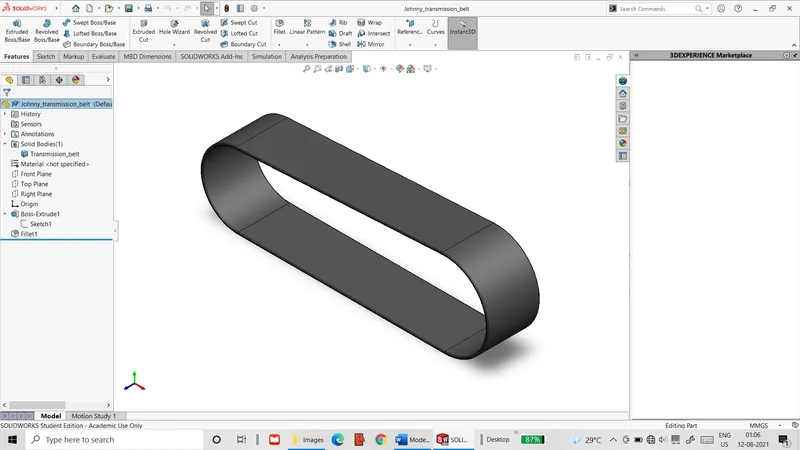 Figure 1: Transmission belt model
- The belt is the simplest of the parts to model. It is created by extruding a simple sketched loop consisting of lines & arcs.
- The belt is also provided with the appearance of matte rubber.
- Kickstand:
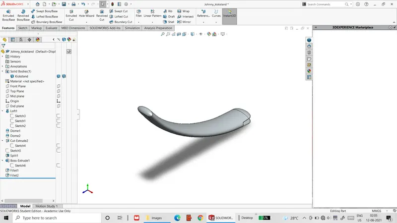 Figure 2: Kickstand model
- The kickstand is created by creating a lofted extrude between 2 ellipses along a spline curve. The resultant flat ends are capped off with elliptical domes.
- An extruded cut and a straight extrude is used to model the pivot point. Additionally, a small flat surface is generated at the bottom by splitting the solid using a straight line.
- The appearance assigned to this part is that of polished chrome.
- Front fender:
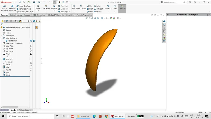 Figure 3: Front fender model
- The front fender is created by a revolved extrude, as shown above.
- The top & bottom tips are created by splitting the solid with mirrored spline curves and deleting the separate solids.
- The part is given a metallic gold colour.
- Rear fender:
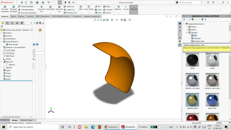 Figure 4: Rear fender model
- Like the front fender, the rear fender is created by a revolved extrude.
- The rounded corners are achieved by the use of fillets with relatively large radii.
- This part is also given a metallic gold colour. A decal is to be applied in this project.
- Oil tank:
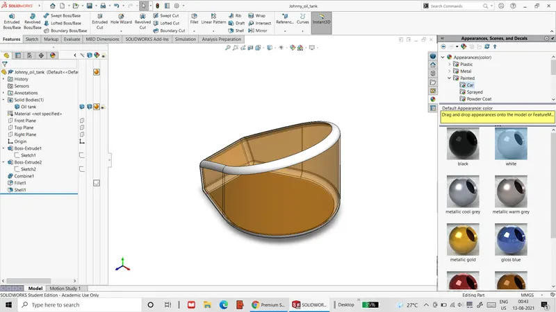 Figure 5: Oil tank model
- This part is created as a common intersection of two straight extrudes.
- The resultant solid is then converted into a 3mm thick shell.
- The part is given the metallic gold colour along with white highlights along the edges.
- Foot pedal:
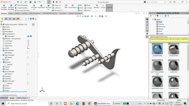 Figure 6: Right foot pedal model
- This part is created with a combination of straight and revolved extrudes.
- The ridges are modelled as a linear pattern of an extrude.
- The part has a mirror part for the other side of the chopper.
- These parts are given a polished steel appearance.
- Chain:
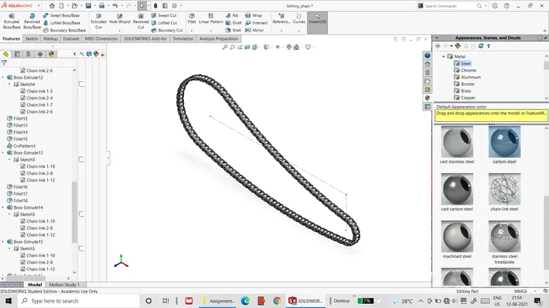 Figure 7: Chain model
- The chain is comprised of individual chain links that are built with straight extrudes.
- The chain links are repeated as a curve driven pattern, with the curve used for the pattern comprised of 4 arcs.
- This part is purely included for cosmetic purposes.
- The chain is also given a carbon steel appearance.
- Front wheel:
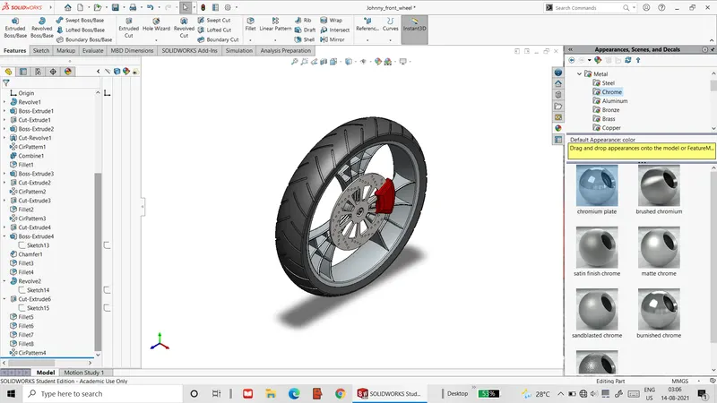 Figure 8: Front wheel model
- The front wheel is constructed by having the outer rim and the tyre region revolved, while the spokes are made as a circular pattern of straight extrudes and cuts. The tyre region also has a circular pattern of extrude cuts for the tyre treads.
- The brake disc and calliper are made with straight extrudes. The holes in the disc are made with circular patterns of extrude cuts, as well as linear pattern for the circular holes.
- The spokes are given a polished chrome appearance, while the tyre region is given a rubber appearance and the brake disc is given a carbon steel appearance. The brake calliper is given a spray paint red colour.
- Rear wheel:
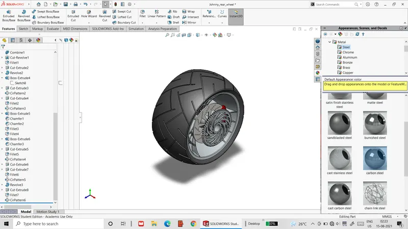 Figure 9: Rear wheel model
- The rear wheel is modelled in a similar manner to the front wheel.
- The sprocket is modelled like the brake disc and is also given a carbon steel appearance.
- Steering fork:
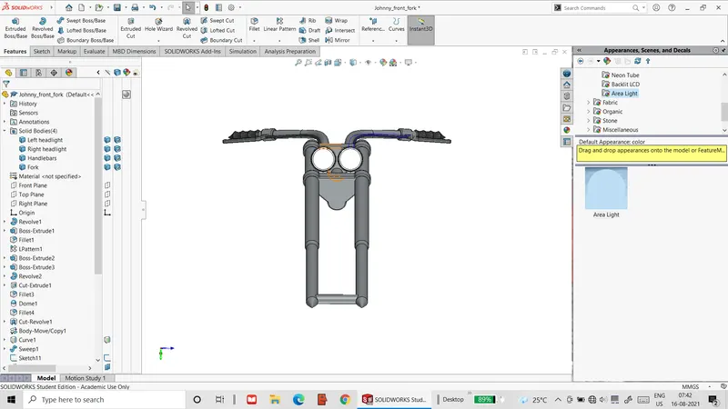 Figure 10: Steering fork model
- This part is created as one half that is mirrored about a central plane. This part consists of a combination of straight & revolved extrudes, and linear patterns.
- The lever region is modelled as a straight extrude of a sketch defined on a custom reference plane, and the cables are generated by sweeping a circle along a projected curve defined by 2 separate curves defined in perpendicular planes.
- The headlamps have domes for lenses that are given an area light appearance to simulate emitted light.
- The fork body is given a polished chrome appearance, while the handles and cables are given a matte rubber appearance.
- Chassis:
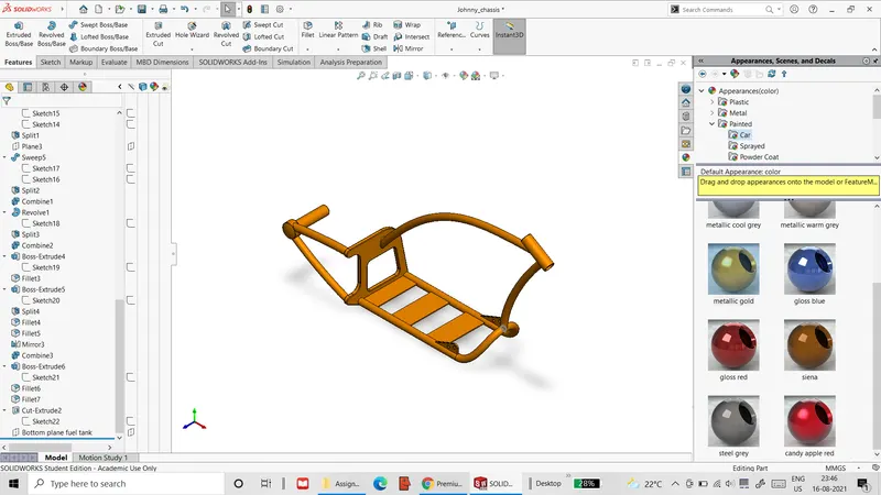 Figure 11: Chassis model
- The chassis is made by straight & revolved extrudes, mirrored entities and sweep extrudes along projected curves and spline curves.
- The chassis is given the same metallic gold as most of the other parts.
- Engine:
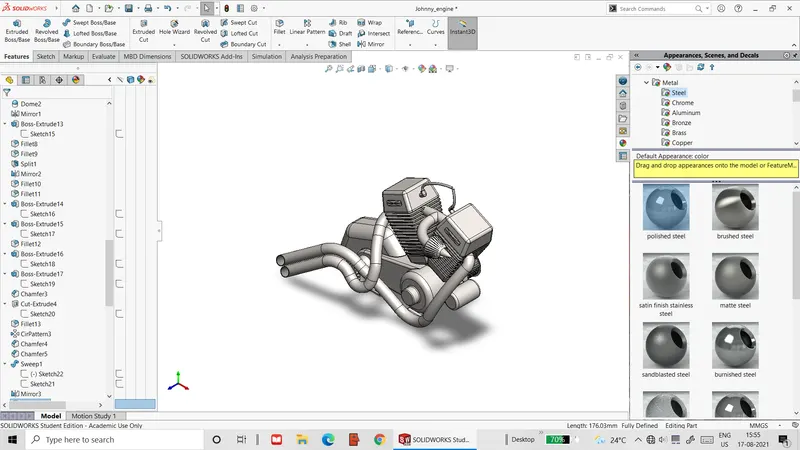 Figure 12: Engine model
- This the most geometrically complex part in the chopper assembly.
- It is constructed using all the modelling operations used in the previous parts- straight & revolved extrudes, mirrored entities, linear & circular patterns of extrude cuts and sweep extrudes along curves.
- The most complex section in this part is the exhaust pipes. They are modelled by sweeping 2 concentric circles along compound curves that are created by combining multiple projected curves.
- Finally, the entire part is given the polished chrome appearance.
- Fuel tank:
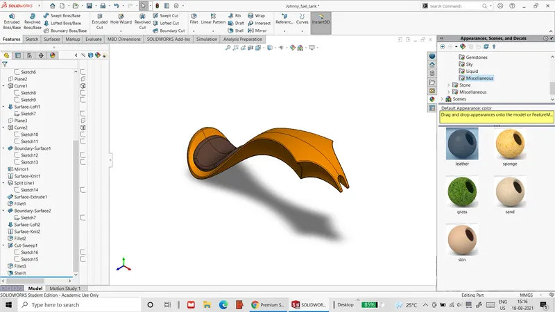 Figure 13: Fuel tank model
- This part is created almost entirely by lofting surfaces between spline curves.
- In order to create fillets, the resultant body has to be converted to a solid, and then converted back into a shell after defining the fillets.
- This is the final part to be imparted the metallic gold colour, along with a leather appearance for the seat, and during the course of this project, will have 5 decals applied to its sides and top.
The final assembly of the chopper is illustrated below.
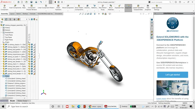 Figure 14: Full chopper assembly
Procedure: The images for the model are prepared through the following sequence of steps.
- The assembly file for the chopper model is opened with Solidworks.
- After ensuring that none of the mates defined in the assembly model involve the assembly space, the chassis part of the assembly is made free-floating by right-clicking on the part in the assembly tree and choosing the float option.
- A new mate relation is defined, where the outer central surface of the rear tyre is tangent with the top plane of the assembly space.
- In another new mate, the lower surface of the kickstand is made tangent with the same top plane.
- The handlebars of the chopper are moved as far to the left as permitted by its limit angle mate. This is followed by applying a tangent mate between the outer surface of the front tyre and the top plane.
- The kickstand part is selected for modification by right-clicking the part in the assembly tree and selecting the ‘edit part’ option. In this part, the sweep curve is edited such that the kickstand is slightly shorter and its lower flat surface is roughly horizontal, as shown below.
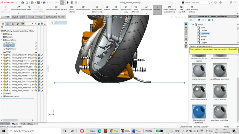 Figure 15: Shortened kickstand with top plane mates
- After the part is edited, the mates that have been affected such that they are over-defined are rectified by suppressing and un-suppressing them. This is done by right-clicking on these parts in the assembly tree and selecting the ‘suppress/un-suppress’ option.
- After returning to the assembly file, the Photoview 360 add-in is activated by selecting it in the ‘Solidworks add-in’ tab. The fuel tank’s part file is then opened.
- In the fuel tank part file, the ‘edit decal’ option in the ‘render tools’ tab is selected for application of decals. The image file for one of the tank’s decals is then imported and projected normal to the XY plane, onto the tank on both of its sides. The blank side of the image file is masked using the decal image’s alpha channel, and under the illumination section, the underlying appearance checkbox is ticked.
- In a similar manner, a second decal is placed on the top side of the tank projected normal to the XZ plane.
- Decals are also applied to the rear fender and the oil tank. Here, the decals are projected as labels onto the fender and oil tank.
- In the assembly file, the perspective view is activated in order get non-orthographic view of the chopper assembly. This is followed by minimizing the feature tree & appearance tabs and adjusting the view of the assembly until it attains a visually appealing position. This view is then saved as a new view, as shown below.
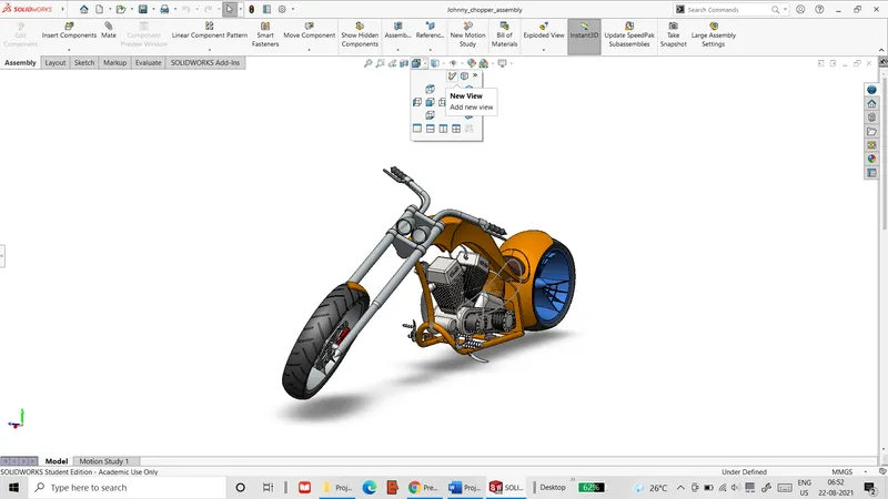 Figure 16: Custom view definition
- The View>lights and camera>Add camera menu selection is used to define a camera angle for this part. Here, the field of view of a 35mm wide angle lens is used. The camera and depth of field for the same are then positioned for optimal placement, as shown below.
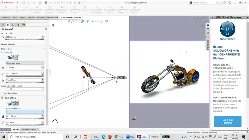 Figure 17: Camera definition
- After applying a plain white background, the display manager tab is used to edit the background scene so that the floor offset is set to a value (57.75 mm) such that the chopper is slightly below the floor of the background, simulating the slight depression of the tyres at ground level, as shown below.
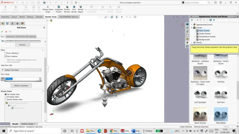 Figure 18: Final positioning & scene composition
- In the same background setting, the environment reflected is changed to another image titled ‘daytime’ that shows a daytime street view, as shown below.
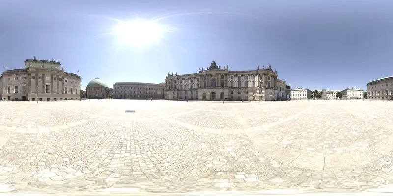 Figure 19: Image file for reflections
- In the ‘render tools’ tab, the preview window tool is selected to show a preview of the rendered image that will be generated from the given orientations and camera angles.
- In the same ‘render tools’ tab, the ‘options’ tool is used to define the final settings for the rendered image. The image is chosen to have a resolution of 1280 X 720 (Full HD) with maximum render quality and a local directory file where the image will be saved. The ‘Final render’ tool is then chosen to begin the full rendering process.
- Once the final image quality is verified to be good, the image is then saved.
- The left side view of the chopper is then selected for the next rendered image. A new camera is defined at the left side and the view is switched to this camera view. For this image’s render options, contour rendering is selected. This view is then fully rendered and the image is verified and saved.
- For the third image, the right-side view of the chopper is selected along with a soft spotlight background and another camera is defined for this view. Also, cartoon rendering is chosen in the rendering options. The cartoon render includes shades as well as edges.
- For the fourth image, the first camera view is used. Here, the background used is changed to the daytime background that was used for the reflections off the chopper. Also, depth of field is turned off in order to avoid blurry regions.
- For the fifth image, the front view is used.
- For the final image, the top view is used to show the top decal on the fuel tank.
Result: The final rendered images are compiled below.
- First camera view (almost isometric):
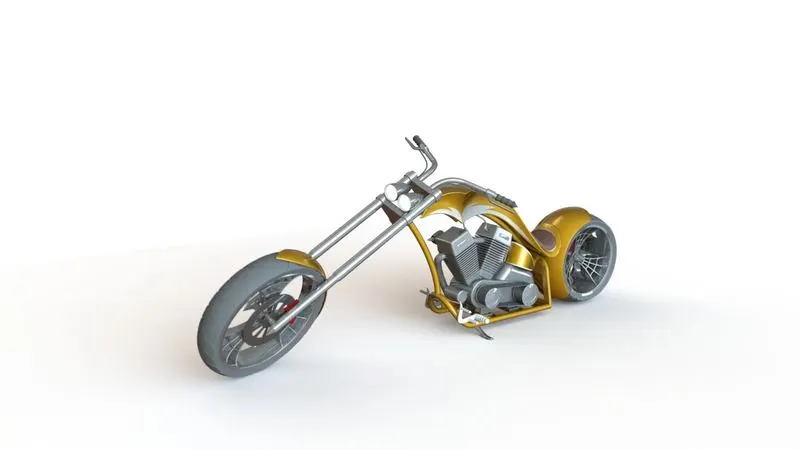 Figure 20: Rendered image of chopper in plain white background
This image prominently shows the chopper and most of its details. While the chrome parts reflect the background as intended, the details in the reflections themselves are hard to make out due to the extreme curvature or small size of the reflective surfaces, as well as the presence of the plain white background. In addition to this, the tyre treads on the front wheel appear a bit blurred due to the depth of field setting in the camera used.
- Second camera view (Left side):
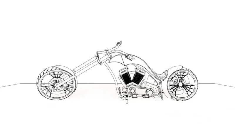 Figure 21: Contour rendition of chopper for use as sketch
This image shows the chopper without any colour or shading. Since the rendering process foregoes these aspects, this type of image was the fastest to be rendered (just over 10 minutes). Hence, this type of image is well suited for quick image generation meant for use in manuals or similar documents.
- Third camera view (right side):
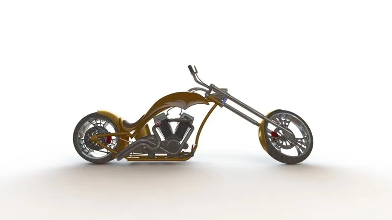 Figure 22: Cartoon rendition of chopper
This image shows the cartoon rendition of the chopper that shows the chain and exhaust pipes that were obscured in the previous images. It is to be noted that even when this was not a realistic rendition, it took the most amount of time to create (nearly 40 minutes). This can be attributed to two factors. One of them is the need to recognize edges & contours that need to be highlighted as solid lines. The other factor is the lack of colour gradients within the shaded region. Counter-intuitively, these regions require computation of the colour values at each pixel, which then has to be followed by computation of an average value for regions whose colours fall within a certain range.
- Fourth image (same camera as first with outdoors background):
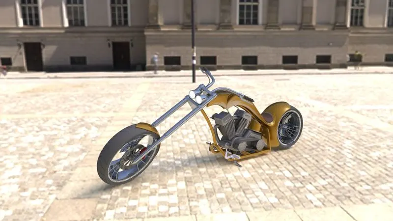 Figure 23: Full rendition of chopper with background
This shows the best image that could possibly be rendered using Photoview 360. The use of the daytime background has allowed for a slightly better lighting than that with the plain white background. This is due to the fact that this background has its own sunlight source that overrides lights that were defined by default for the chopper. Also notable is the elimination of blur from the front wheel, since the depth of field setting is now deactivated. While this may not be a strictly realistic simulation of a 35mm camera image, it does allow for better presentation.
- Fifth camera view (front side):
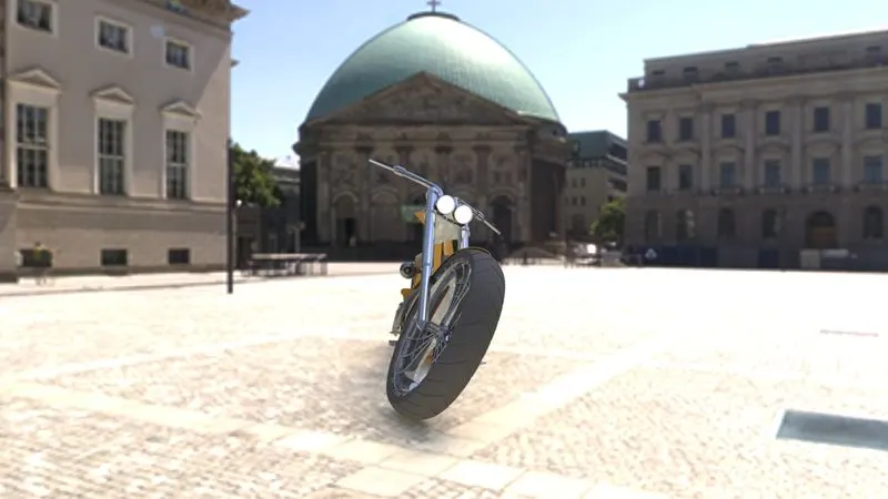 Figure 24: Rendition of front end of chopper
This image shows the front side of the chopper. It shows the effect of perspective on the image. Here, the front wheel appears slightly larger than normal. Hence, such a scene composition is useful for exaggerating certain features of a model. Rendering of this model also took less time since most of the chopper’s features were obscured from view, and as a result did not require rendering of shades & reflections from those areas.
- Sixth camera view (top side):
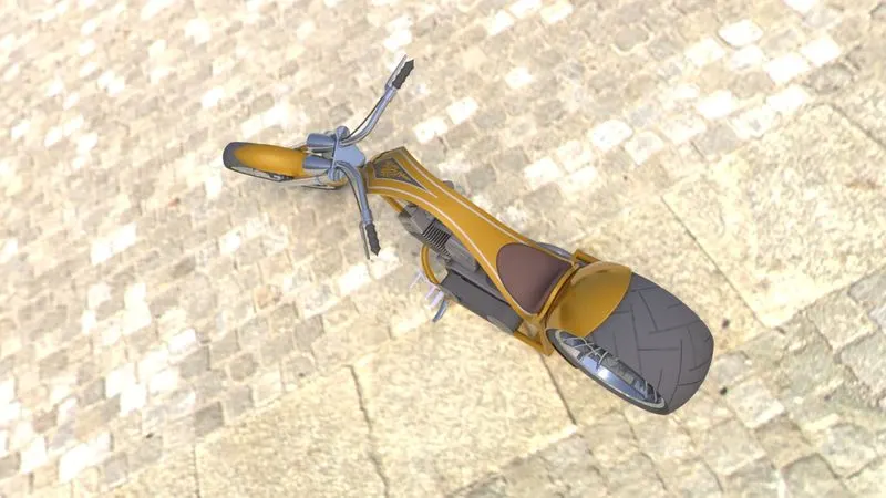 Figure 25: Rendition of chopper as seen from the top
This image shows the chopper as seen from the top. The focal point of this image is the fuel tank and its top decal. It shows that the decal has all its details rendered perfectly, while the un-necessary parts of the decal image have been masked out, verifying the effectiveness of using only the decal image’s alpha channel. The chopper image also demonstrates the limitations of Photoview 360, as the chopper cannot be scaled in correct proportion to the background.
Conclusions: Solidworks Photoview 360 has been successfully demonstrated to show its rendering capabilities with the given CAD model. The images generated show great detail in terms of reflections, shadows, shading etc.