Week 4
Skill-lync ANSA preprocessing assignment (week 4)
Aim: The aim of this assignment is to ensure the correct geometry of the given model, build a representative mid surface for the model, and build an appropriate FE mesh.
Procedure: The following is the catalogue of procedures from importing the geometry to creating the final mesh: -
- Model geometry (bottle cap) is imported in the state shown below.
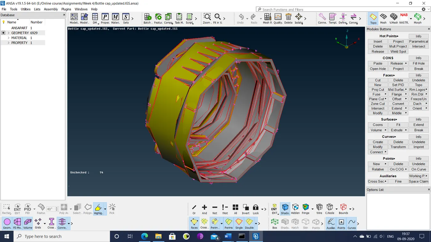
- The faces>topo option is used to stitch the disconnected surfaces of the model together.
- A geometry check is performed on the model to check for remaining errors such as sigle/triple cons or cracks.
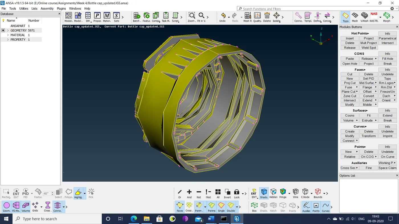
- Any errors detected are fixed using autofix. The fixed geometry is shown below.
- The auxiliaries>free option is used to increase the resolution of the curved edges.
- The mid-surface of the model is generated manually, since the mid-surface>casting option does not accurately generate it.
- The majority of sections such as the outer walls have their mid-surfaces generated via the faces>offset option. Before using the option, the thickness of each section is measured. This measurement is used to set the offset distance as half that value.
- Fins and similar sections have their mid-surface generated using the faces>middle option.
- Wherever there is a gap between 2 mutually perpendicular surfaces, one surface is extended to the other using the faces>extend option.
- If the extended surfaces extend past the other surface, the face is cut using the face>cut option, followed by deleting the overhanging surface.
- When the mid-surface generated has some missing regions, they are filled in using the faces>new option.
- Intersecting surfaces are operated on by the faces>intersect option and the overhanging surfaces deleted.
- Screw thread mid surfaces are generated using middle curves of their top and bottom region.
- The generated mid surface is then extended to the mid surface below.
- The tooth mid surface is generated using a middle curve on the front broad side of the tooth and the edge of the back side.
- The resultant mid surface is then moved to the mid surface below.
- This mid-surface is then copied to generate a circular array.
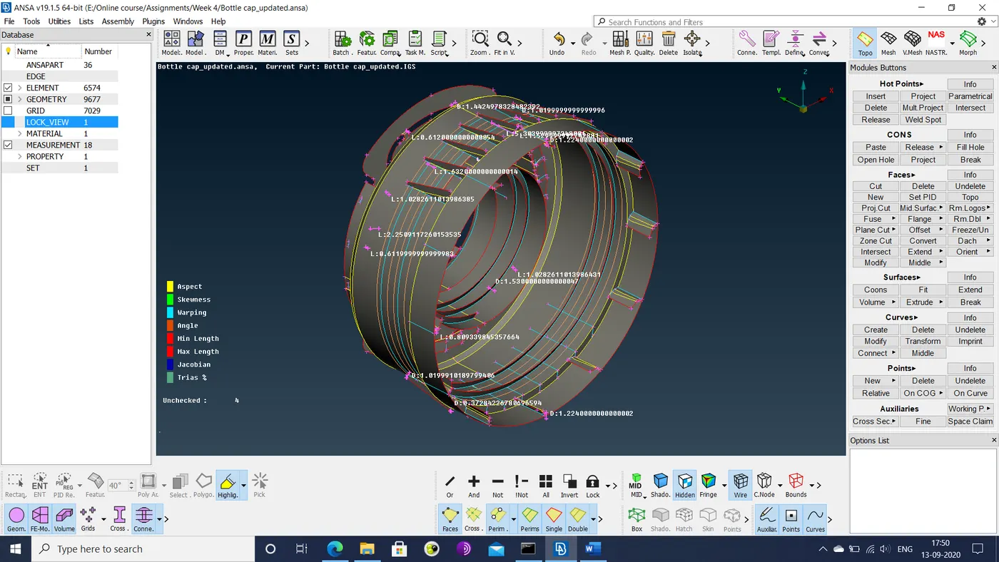
- The final generated mid-surface assembly is shown below.
- The mid-surface assembly is then meshed in compliance with the following quality criteria.
|
S.No |
Quality Criteria |
Value |
|
1 |
Target/Average length |
1 |
|
2 |
Minimum Length |
0.5 |
|
3 |
Maximum Length |
3 |
|
4 |
Aspect |
3 |
|
5 |
Warpage |
15 |
|
6 |
Skewness |
45 |
|
7 |
Jacobian |
0.7 |
|
8 |
Minimum Quad Angle |
45 |
|
9 |
Maximum Quad Angle |
135 |
|
10 |
Minimum Tria Angle |
30 |
|
11 |
Maximum Tria Angle |
120 |
|
10 |
Tria Percentage |
15 |
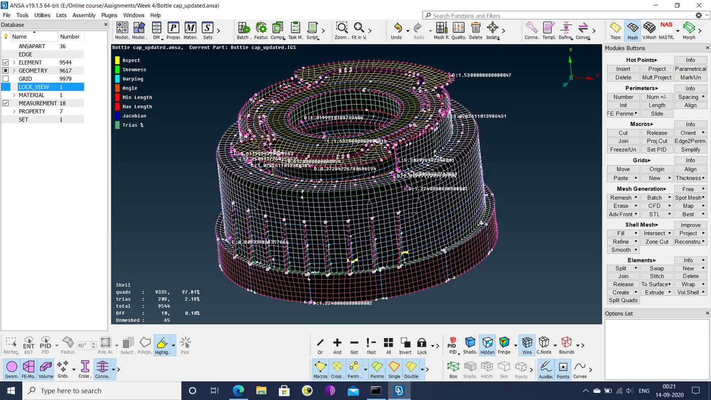
The final mesh is shown below.
- Separate material properties (thickness) are assigned to the respective mid-surfaces.
Learning outcomes: The process of generating mid surface for and meshing a 3-dimensional component has proven to be more challenging than doing the same for a sheet metal component. A number of complications arose during the exercise.
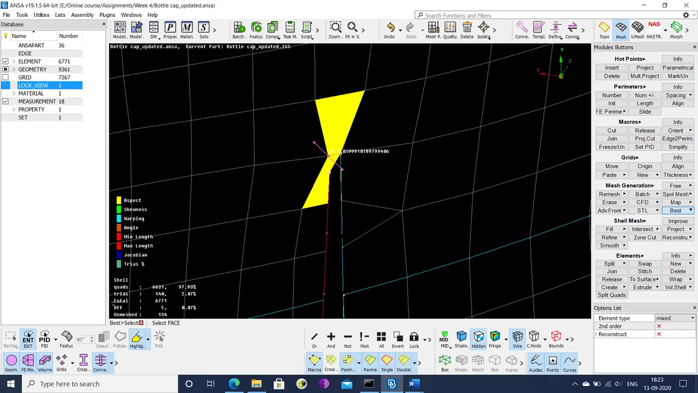
- When a number of mid-surfaces intersect, the freedom of meshing is much more restricted. Many hot points and cons cannot be deleted. The following image shows that since teeth in the model were too close to the inner rim, the mesh elements would have been too small to meet quality criteria. As a result, those regions had to be left unmeshed.
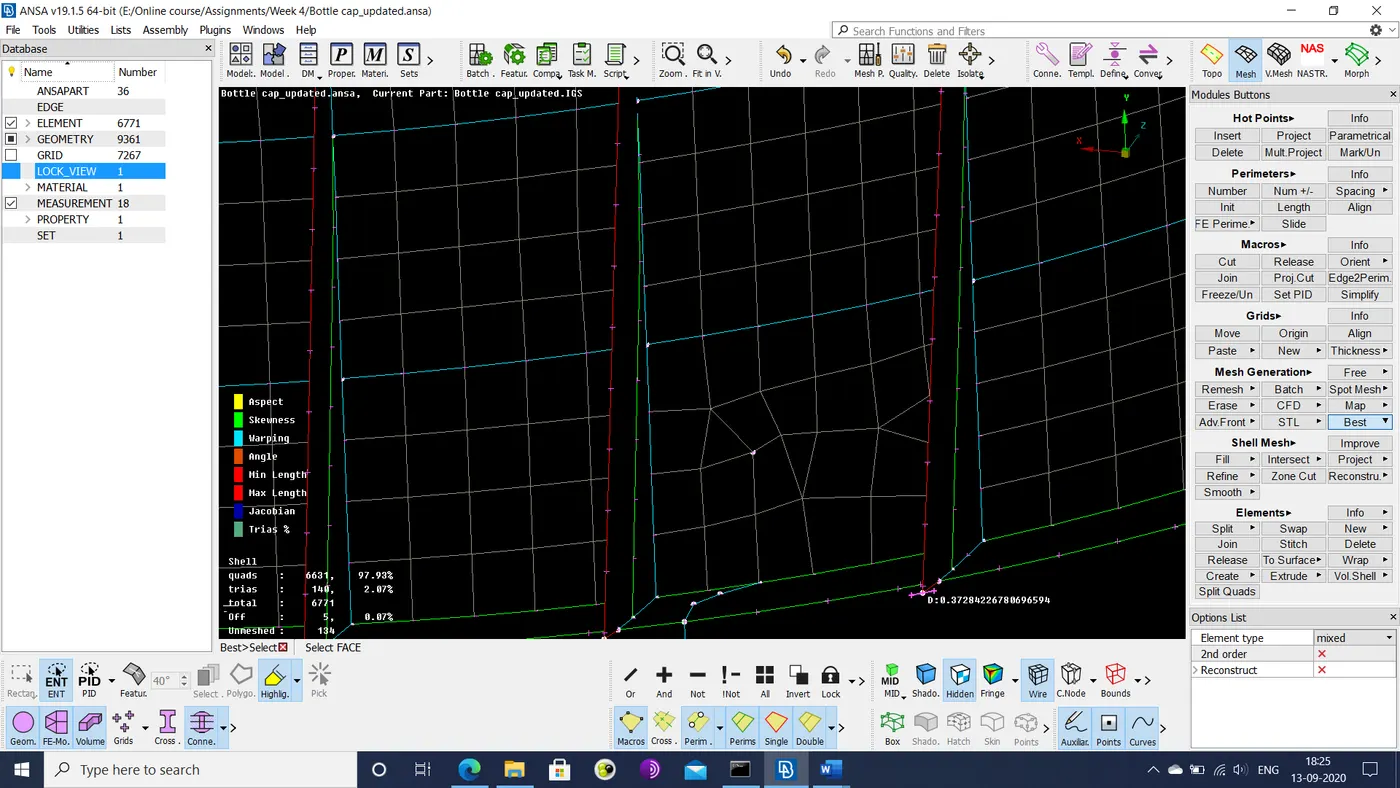
- Some hot points that were used for measuring thicknesses could not be deleted. As a result, the mesh was of low quality in those areas, as shown below.
- The fill hole option could not generate a proper surface when used in the outer wall mid-surface. As a result, some sections of that surface could not be meshed until later, when these surfaces were cut up.
- The greatest challenge here has proven to be generating suitable mid-surfaces. Even if these mid-surfaces are made perfectly, defeaturing is inevitable. This is due to the fact that intersecting surfaces/edges make up the cons and hot points that cannot be deleted. So if their presence results in mesh elements that will never meet the specified quality criteria, additional cons need to be introduced. In the worst case scenario, they lead to areas that cannot be meshed at all and can only be minimized as much as possible.
Conclusions: This assignment has highlighted the challenges and approach to meshing 3d models with multiple mid-surfaces. Options available for optimizing the mesh are heavily restricted due to intersecting surfaces. For generating the best possible mesh, it would greatly help if the starting model has been built with the mesh quality criteria being considered or vice-versa.
Google drive link: https://drive.google.com/file/d/1NWQPJ82j4cnDmgpS6QONOqCIdkBZYNSA/view?usp=sharing