Week 8-3D Tetra Meshing Challenge
Skill-lync assignment (week 8)
Aim: The objective of this assignment is to generate 3D FE meshes for the given components using the specified methods that meet the specified quality criteria.
Case setup: Three components are provided for meshing purposes. The first component is a hub and cover assembly, as illustrated below.
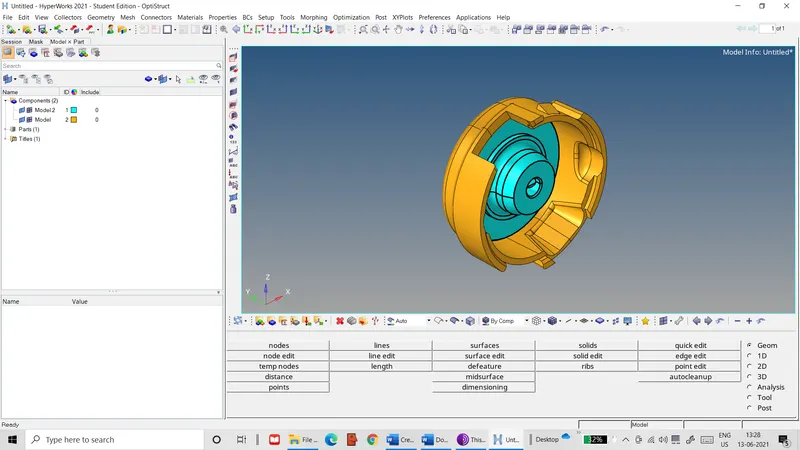 Figure 1: Hub & cover assembly
These parts are to be meshed first by generating a surface mesh, followed by 3D meshing using this surface mesh. They are to be meshed with tetrahedral elements with the following quality criteria.
- Minimum element size: 2 units
- Target element size: 5 units
- Maximum element size: 7 units
- Maximum tet-collapse: 0.15
The second component is shown below.
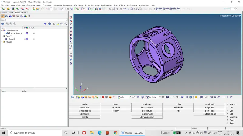 Figure 2: Second housing
It is to be directly meshed using the volume tetra mesh option with the following quality criteria.
- Target element size: 3 units
- Maximum tet-collapse: 0.15
The third component is a turbocharger assembly, as shown below.
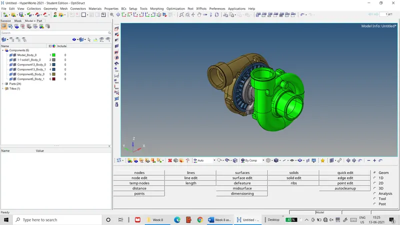 Figure 3: Turbocharger assembly
Like the second component, it is to be meshed using the volume tetra mesh option with the following quality criteria.
- Target element size: 4 units
- Maximum tet-collapse: 0.15
Procedure: The components are worked on through the following sequence of steps: -
- The geometry file of the first component is imported into the Hyper-works workspace.
- The hub section is isolated and the solid defined in this section is deleted.
- The remaining surfaces of the hub section are then checked for geometric errors such as free edges and small fillets.
- The quality criteria for the mesh are then input into the criteria file settings.
- The automesh tool is then used to generate the 2D mesh on the hub surface with triangular elements.
- The qualityindex tool is then used to check the element quality and fix elements that fail the quality criteria.
- The 3d>tetramesh tab is then used to generate the tetrahedral elements from the 2D surface mesh.
- The Tool>check elems tab is used to check for tetrahedral elements that fail the tet-collapse criterion.
- Steps 2-8 are then repeated for the housing section.
- In a new Hyper-works session, the second component is imported and checked for geometric errors.
- In the 3D>tetramesh tab, the volume tetra option is chosen to mesh the solid component with a target element length of 3 units.
- The finished tetra mesh is checked for tet-collapse by the Tool>check elems tab.
- When tet-collapse is detected, the tetra remesh option in the 3D>tetramesh tab is used to recreate the mesh.
- Remaining failed elements are manually fixed by moving one of its nodes outwards with the Tool>translate tab, as shown below.
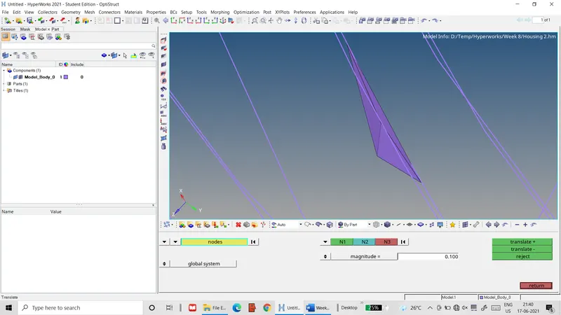 Figure 4: Element failing tet-collapse criterion
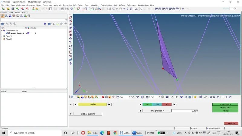 Figure 5: Element after node is translated
- In some cases, elements are deleted and the free nodes are connected by the 2D>replace tab.
- Steps 10-15 are repeated for the third component. This component is meshed section-by-section.
- If the number of failed elements in any section is too great, the mesh is deleted and the section is defeatured, removing any surface fillets or fine features. The solid is then recreated from the modified bounding surfaces by the Geom>solids>bounding surfaces tab. The mesh is then recreated from this solid.
Results: The final 3D meshes for all the components are compiled below.
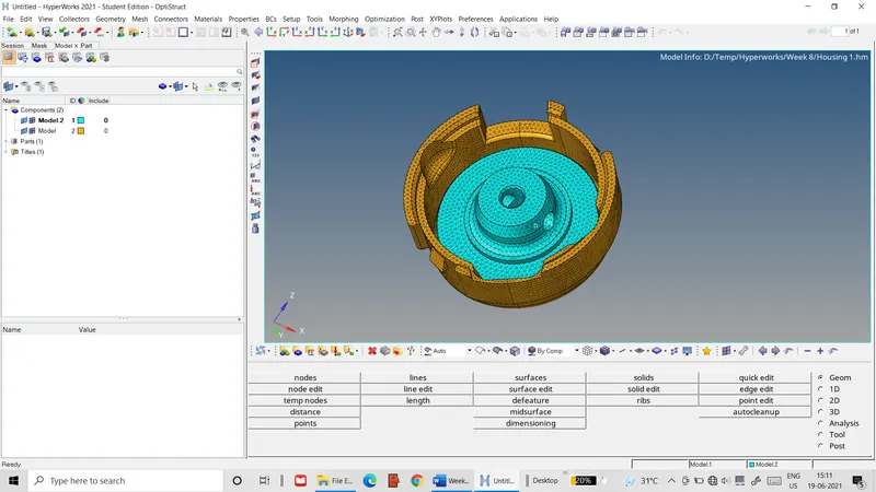 Figure 6: 3D mesh of hub and cover assembly
Manually generating the mesh from the 2D surface mesh took the greatest amount of time but had the best 3D mesh quality of all the components. Ensuring quality of the 2D mesh resulted in the complete absence of tetra collapse in any of the terahedral elements created.
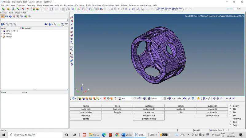 Figure 7: 3D mesh of housing component
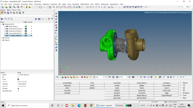 Figure 8: 3D mesh of turbocharger assembly
Direct volume meshing took less time than manual meshing, but created lower quality meshes. The number of elements failing for tet-collapse was significantly high and cleaning these elements took just as much time as manual meshing. Defeaturing the components of its finer features reduced the cleanup required, however complex geometries like the turbine housings of the turbocharger assembly would have taken a significantly long time to defeature. So those features were left intact. After the tet-collapse was remedied, the final mesh still had plenty of flaws like protusions and nodes not aligned with surfaces/edges. Due to time constraints, these flaws were not worked on.