Project 2
Skill-lync project 2
Aim: The objective of this project is to generate an appropriate FE mesh for the given component that meets the specified quality criteria. Representative mid-surfaces are to be created for their respective sections and meshed. The final objective is to create appropriate connections between the various sections.
Procedure: The component is meshed using a wide variety of methods that are catalogued below.
- The component is imported into the ANSA workspace in the following state.
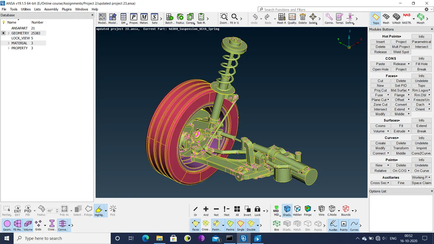
Figure 1: Imported geometry
- The individual sections of the component are then checked for geometric errors, and any found are fixed either via the auto-fix option or manually by deleting/recreating faces and releasing triple cons.
- The sections with geometries too intricate for the specified quality criteria are altered geometrically as shown below.
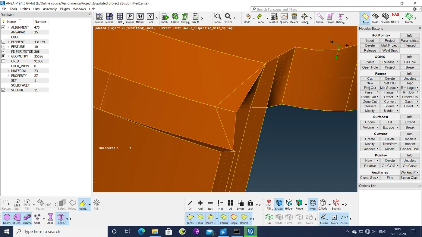
Figure 2: Corner before modification
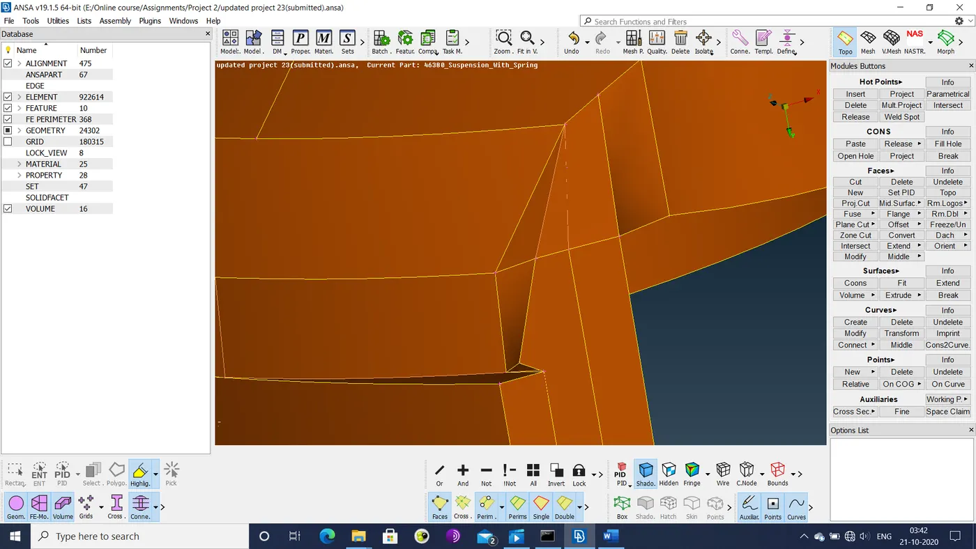
Figure 3: Corner after modification
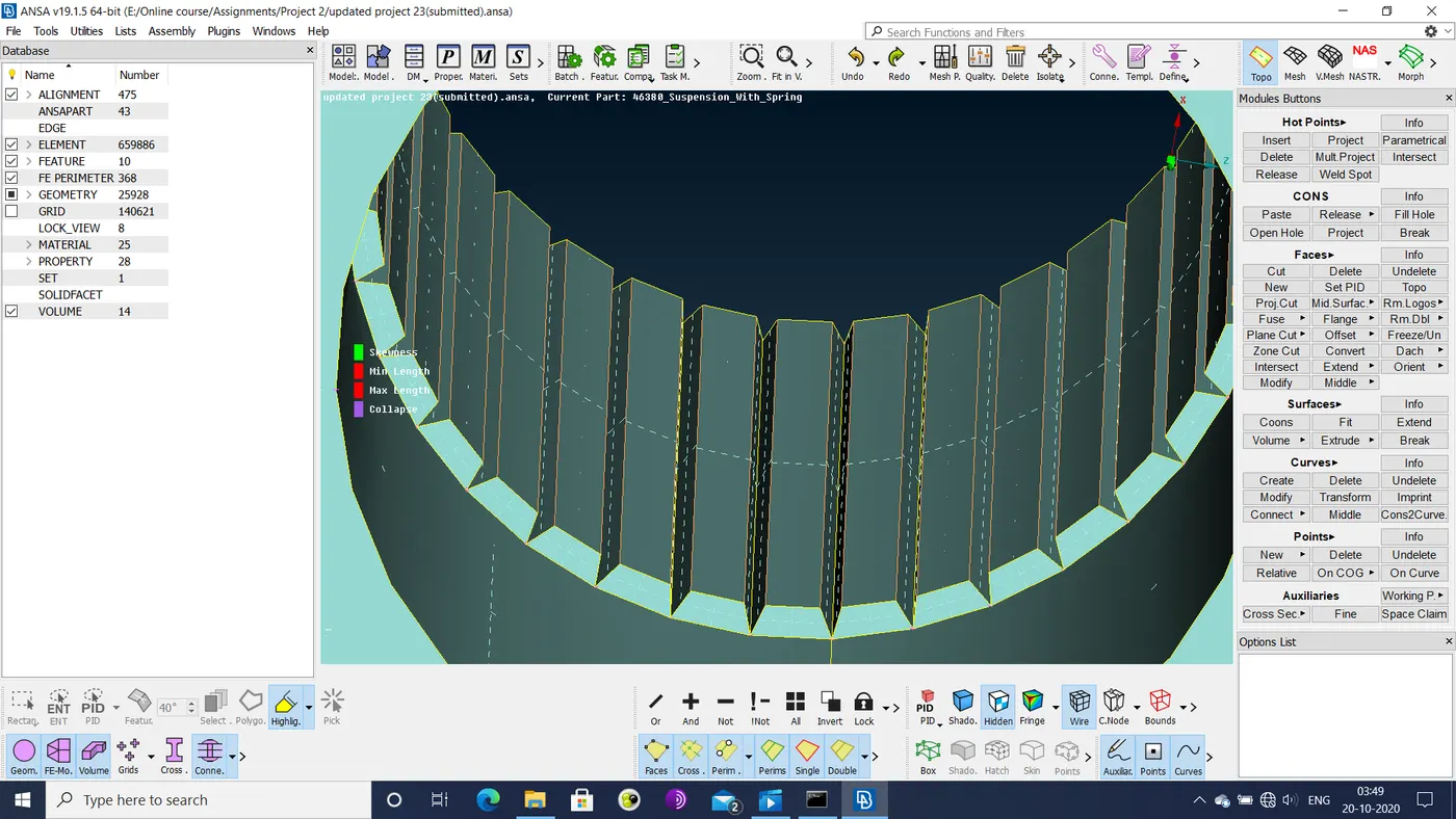
Figure 4: Axle splines before modification
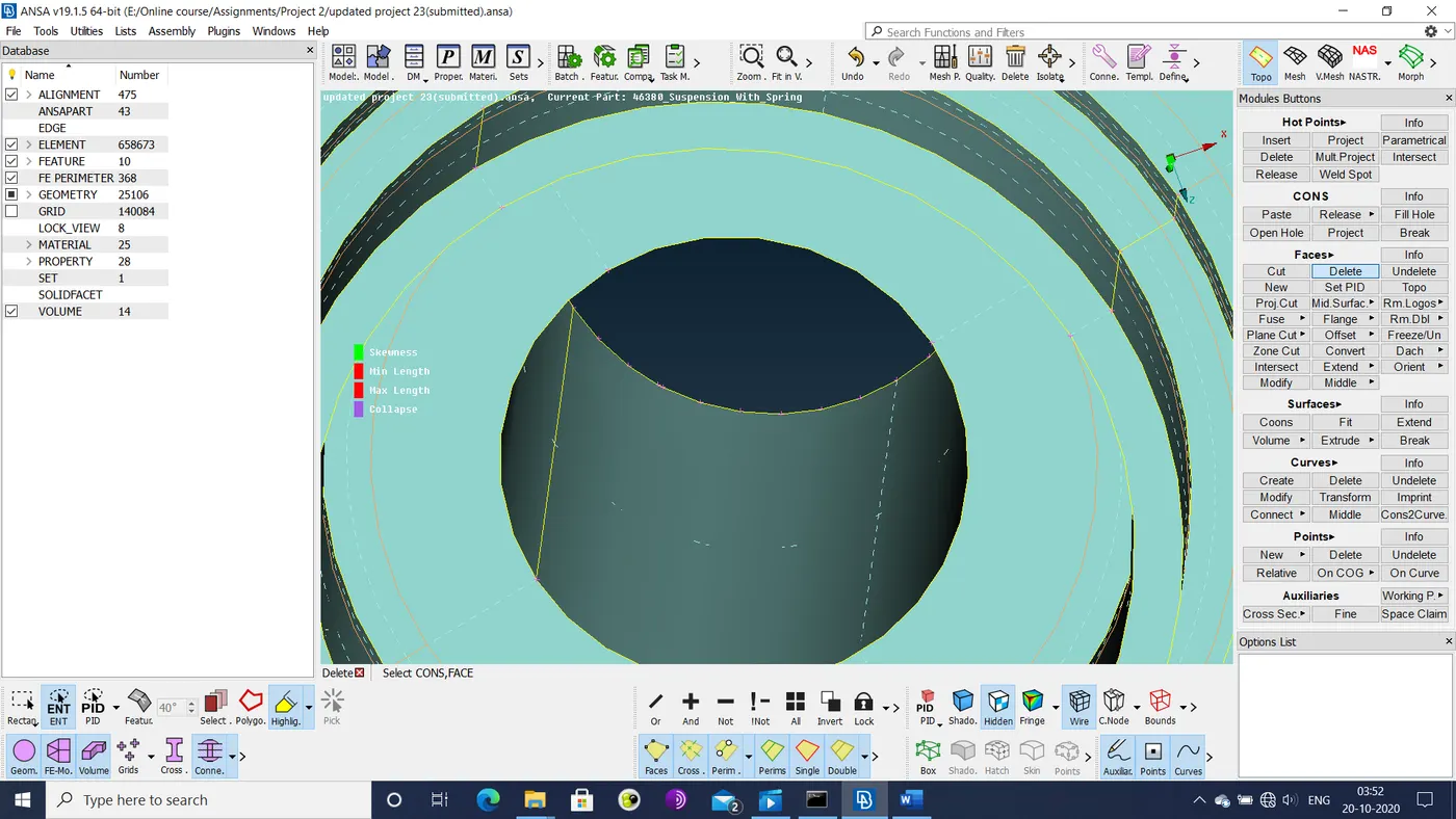
Figure 5: Axle splines after modification
- The sections that can be represented with a mid-surface are identified. The sections that require volume meshing are worked upon first.
- For volume mesh of the sections other than the tyre and the rim, the following quality criteria are set.
|
S.No |
Quality Criteria |
Value |
|
1 |
Target/Average length |
4 |
|
2 |
Minimum Length |
2 |
|
3 |
Maximum Length |
6 |
|
4 |
Skewness |
45 |
|
5 |
Tet-collapse |
0.2 |
- The sections with relatively simple geometries are defeatured and have their surface mesh generated in a single step via batch mesh. The more complex geometries are defeatured and meshed manually.
- The surface mesh is reconstructed/fixed in areas where quality criteria are violated.
- The volumes encased by the shell meshed are defined and meshed using the TetraFEM option.
- For the sections with representative mid-surfaces, the following quality criteria are specified.
|
S.No |
Quality Criteria |
Value |
|
1 |
Target/Average length |
4 |
|
2 |
Minimum Length |
2 |
|
3 |
Maximum Length |
6 |
|
4 |
Aspect |
3 |
|
5 |
Warpage |
15 |
|
6 |
Skewness |
45 |
|
7 |
Jacobian |
0.7 |
|
8 |
Minimum Quad Angle |
45 |
|
9 |
Maximum Quad Angle |
135 |
|
10 |
Minimum Tria Angle |
30 |
|
11 |
Maximum Tria Angle |
120 |
- Most of these sections have their mid-surfaces generated, defeatured and meshed in a single step via the mid-surface>casting option.
- The geometry for the cylinder of the shock absorber has its geometry partially reconstructed so that it is a hollow cylinder with a closed bottom.
- The mid-surface of this geometry is created by the middle option.
- The mid-surface is defeatured and then meshed. The mesh is then reconstructed/fixed in areas where the quality criteria are not met and where the number of triangular elements can be reduced.
- Bolt connections between meshed sections are applied via the bolt option.
- Sections attached to the shocks cylinder are assumed to be connected by seam welds.
- The bracket mid-surface is connected to the cylinder section with overlap-shell elements. The altered mesh of the cylinder is then optimized again.
- The spring stop section is connected to the cylinder with y-joint-shell elements.
- The spring is represented as a 1 dimensional curve.
- The curve is then meshed via the elements>CBAR option in the NASTRAN deck.
- The spring mesh is connected to the spring stop sections by two-node RBE2 connections.
- For volume mesh of the tyre and rim, the following quality criteria are set.
|
S.No |
Quality Criteria |
Value |
|
1 |
Target/Average length |
6.5 |
|
2 |
Minimum Length |
5 |
|
3 |
Maximum Length |
10 |
|
4 |
Skewness |
45 |
|
5 |
Tet-collapse |
0.2 |
- The geometries are then defeatured and have their surface mesh generated.
- The volume mesh is then generated via the TetraFEM option.
- The rim is connected to the wheel axle by a bolt connection, leaving a degree of freedom (DOF) for rotation along the y-axis free.
Learning outcomes: The project has been an exercise in every technique and concept related to FEM mesh and connections covered so far.
- Geometry cleanup and repair was a major bottleneck. Many of the sections in the given component had distorted faces & cons. Some sections like the brake caliper and the wheel axle needed to have entire regions removed so that they could be meshed properly. The cylinder and the bushing section had to be partially reconstructed since the component was an assembly. This meant that some surface information was lost from mating sections.
- Most of the sections were complex 3d structures that could only have a volumetric mesh. Thus meshing for these sections were much easier and faster due to the fewer quality criteria.
- The sections that required mid-surfaces had simple geometries so that the mid-surface>casting option was enough to directly generate the final mesh. The shocks cylinder was an exception.
- Meshing the tyre and the rim proved to be highly problematic, since many of their critical features measured less than the minimum element length of 5 mm. Hence, this value had to be reduced to 4 mm, in order to capture these critical features. Also, the rim model seemed to be incompatible with the given suspension system, as the rim had 4 bolt-holes while the wheel axle had 5. So a single bolt connection had to be made in the central holes of these sections.
Conclusion: The given component was meshed and given appropriate connections between sections using the various techniques covered over the entire course. Volumetric and mid-surface meshes were applied wherever appropriate. Bolt, CBAR, seam welds and RBE2 connections were applied at their respective areas.
Google drive link: https://drive.google.com/file/d/1LIi1pz8Cb8vI2bEh1VrLWb7utwhxR34F/view?usp=sharing