Assignment 1
Skill-lync hyper works assignment 1
Objective: The objective of this challenge is to import the given geometries into the hyper works workspace, check them for errors like free edges and fix any that arise, create a representative mid-surface for the geometries and repair any errors that arise, remove any unnecessary geometric features from those mid-surfaces, and create an FE mesh for these mid-surfaces that meet the specified quality criteria.
Case setup: The first component is a sheet metal unit with a uniform thickness of 0.91 mm. A screenshot of the component is shown below.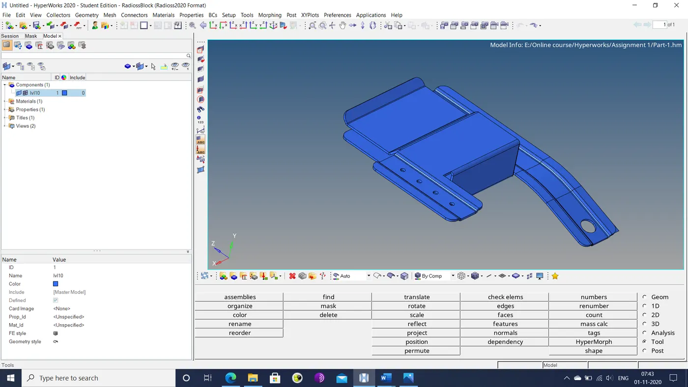
Figure 1: First component (Part-1)
The second component shown below has a uniform thickness of 2 mm.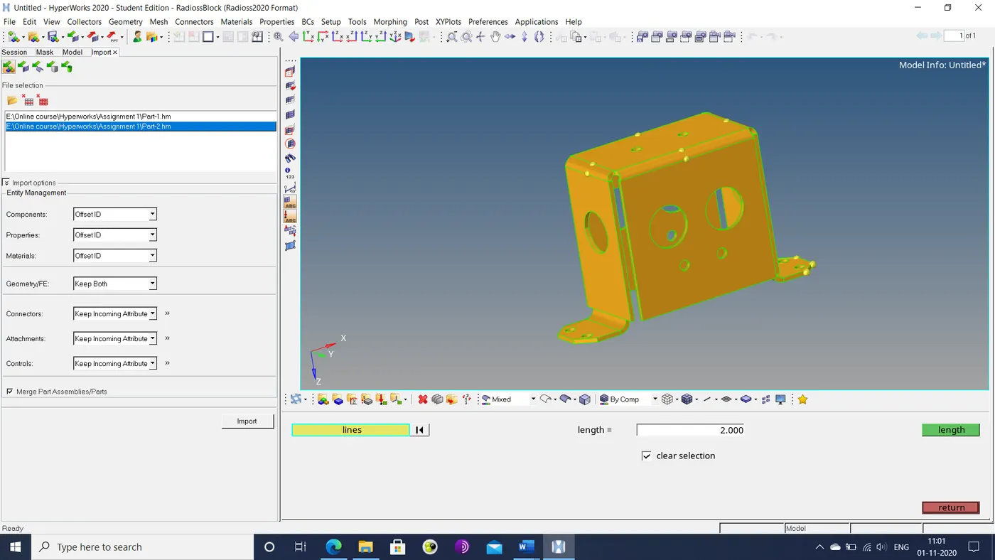
Figure 2: Second component (Part-2)
The third component has a uniform thickness of 1.8 mm.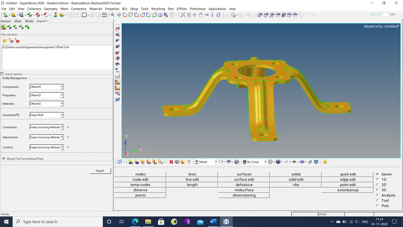
Figure 3: Third components (Part-3)
Procedure: The 3 components are worked on separately. The operations conducted on each component are listed below.
- The component is imported into the Hyper-works workspace.
- The geometry color mode is then set to mixed so that free edges are highlighted in red.
- The geometry>quick edit>toggle edge option is used to combine two free edges that are really close to each other. One such instance is shown below.
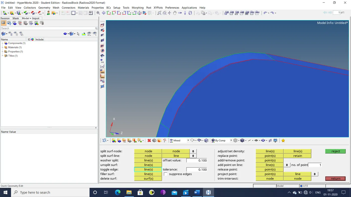
Figure 4: Before toggle edge
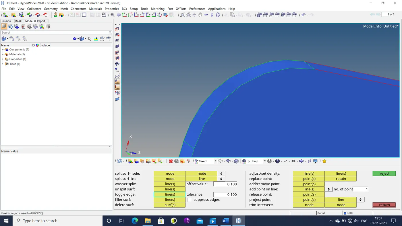
Figure 5: After toggle edge
- An alternative method uses the replace point option in the quick edit tab to merge the end points of these free edges together, as illustrated below.
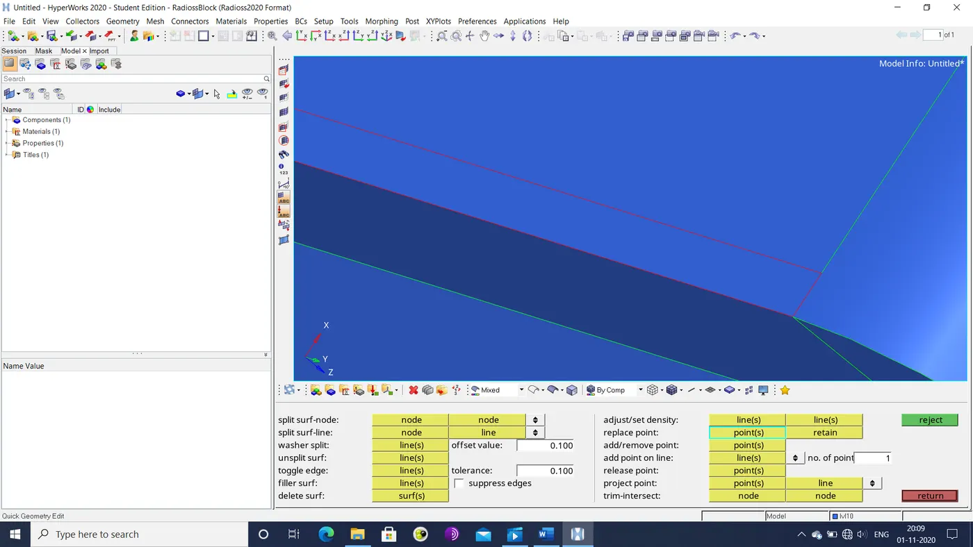
Figure 6: Missing surface
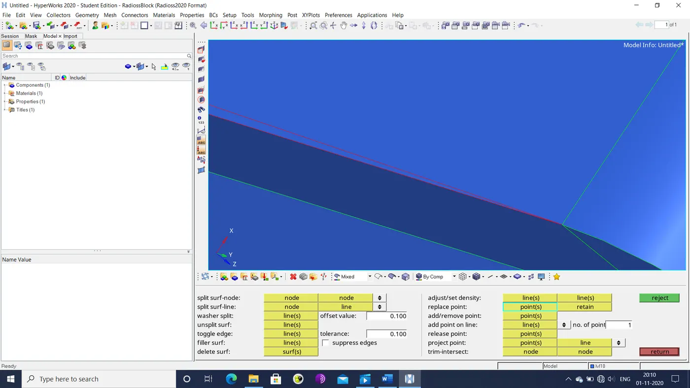
Figure 7: Replacing point at one end
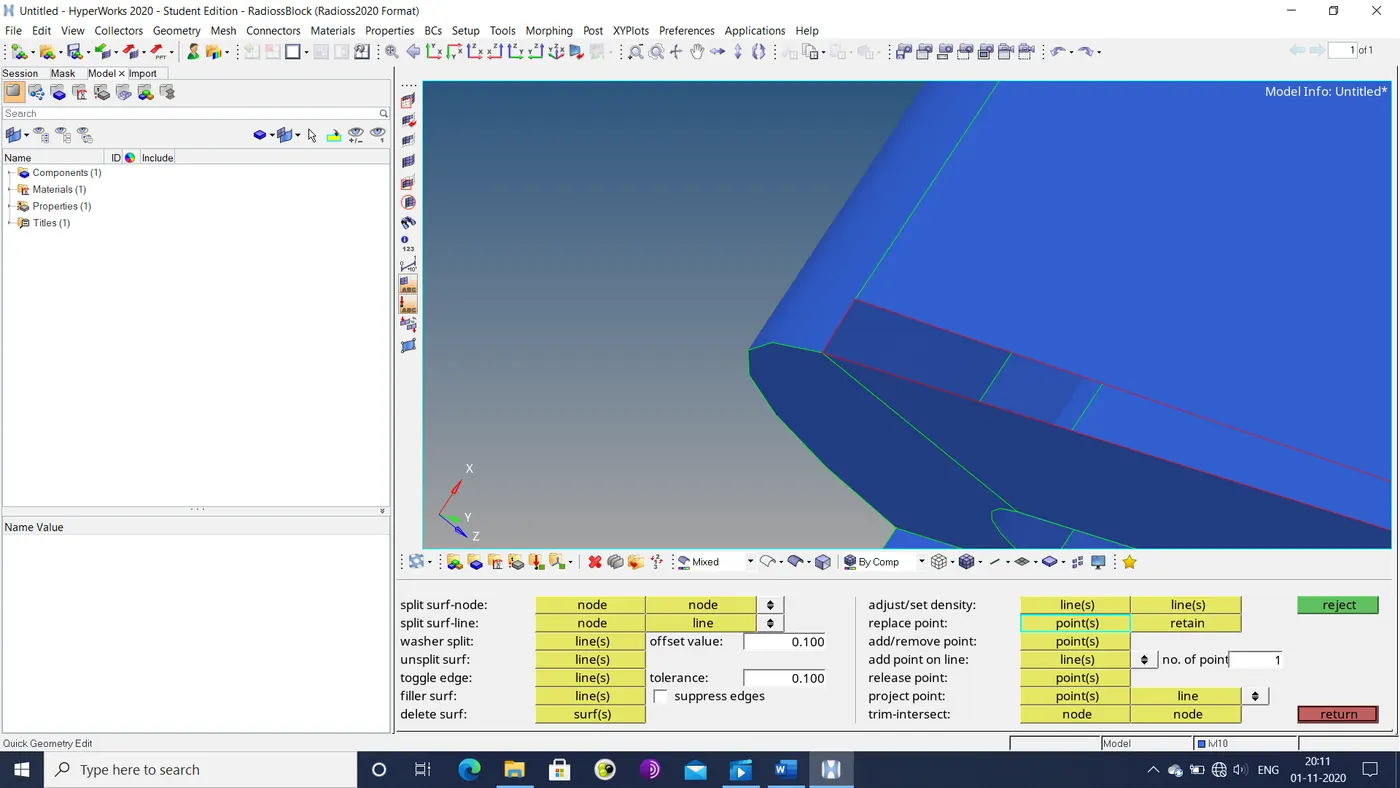
Figure 8: Before replacing point at other end
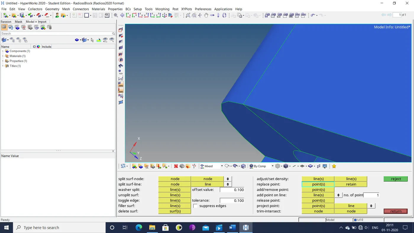
Figure 9: Final stitched edge
- Missing surfaces are recreated using the filler surface option in the quick edit tab, as shown below.
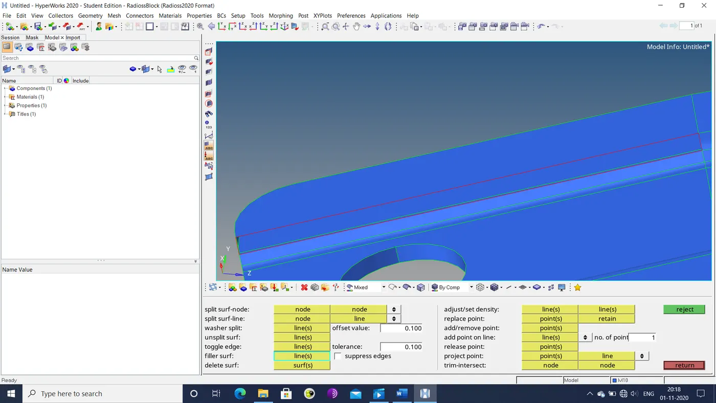
Figure 10: Second missing surface
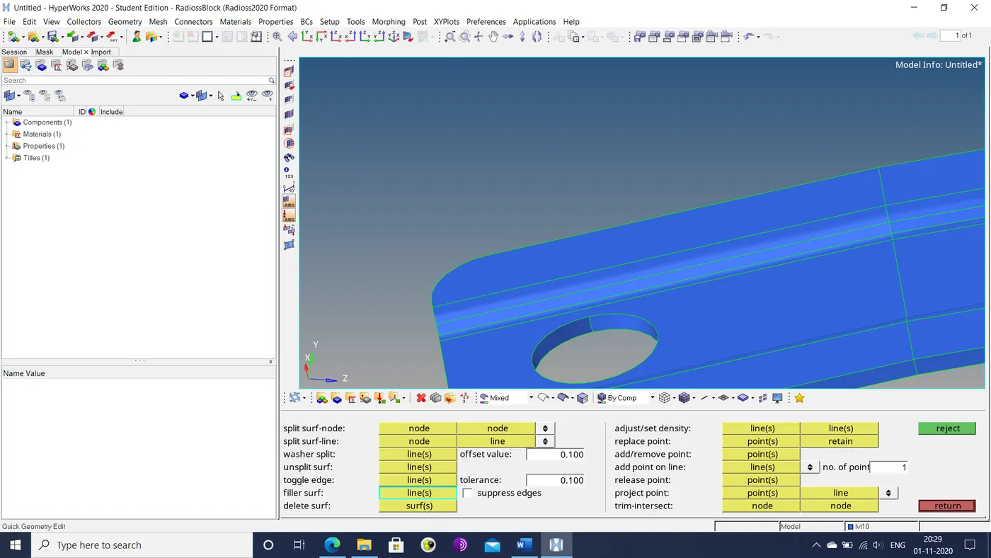
Figure 11: Filler surface
- Unnecessary extra faces are deleted using the delete option, as shown below.
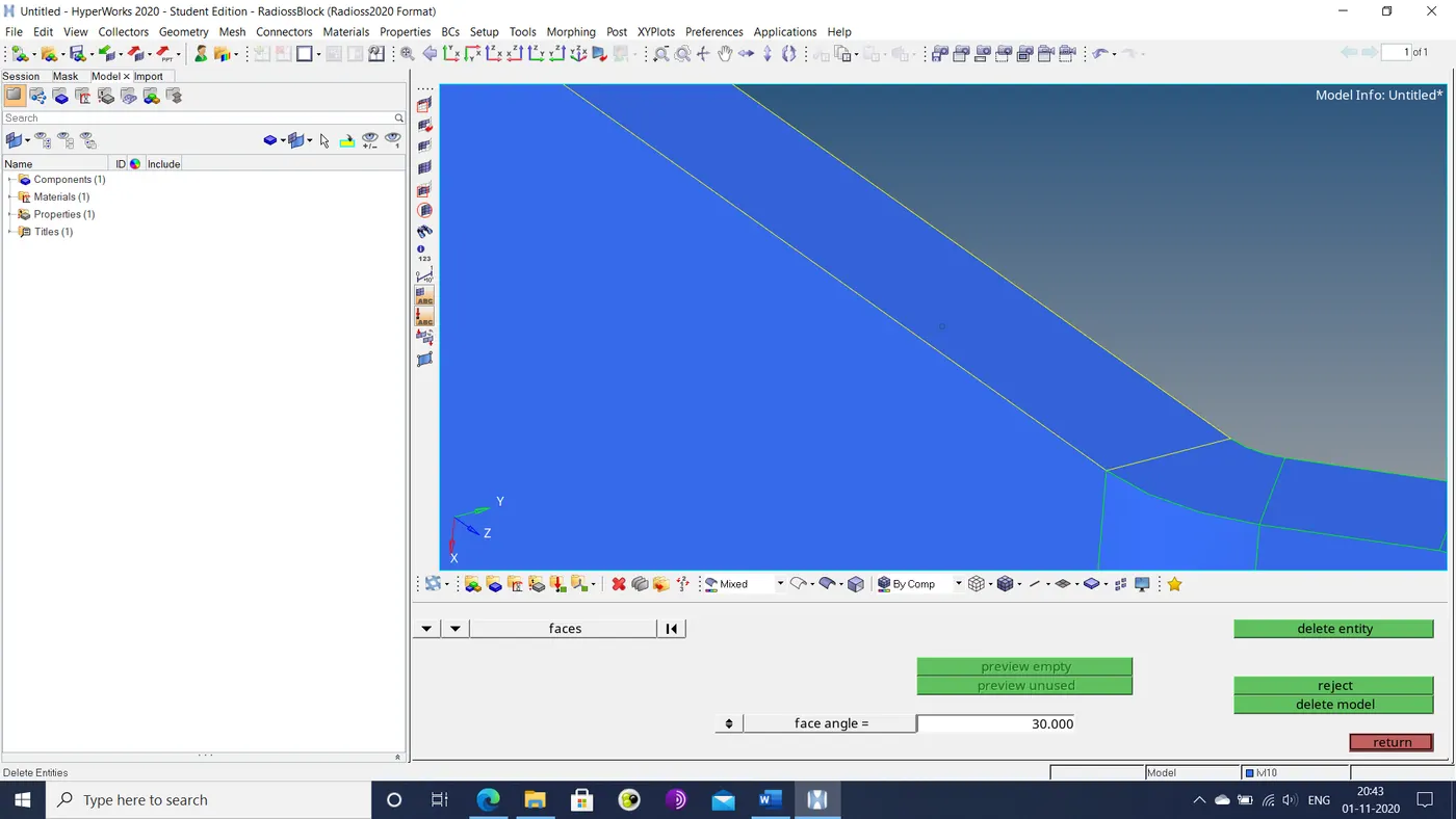
Figure 12: Extra face
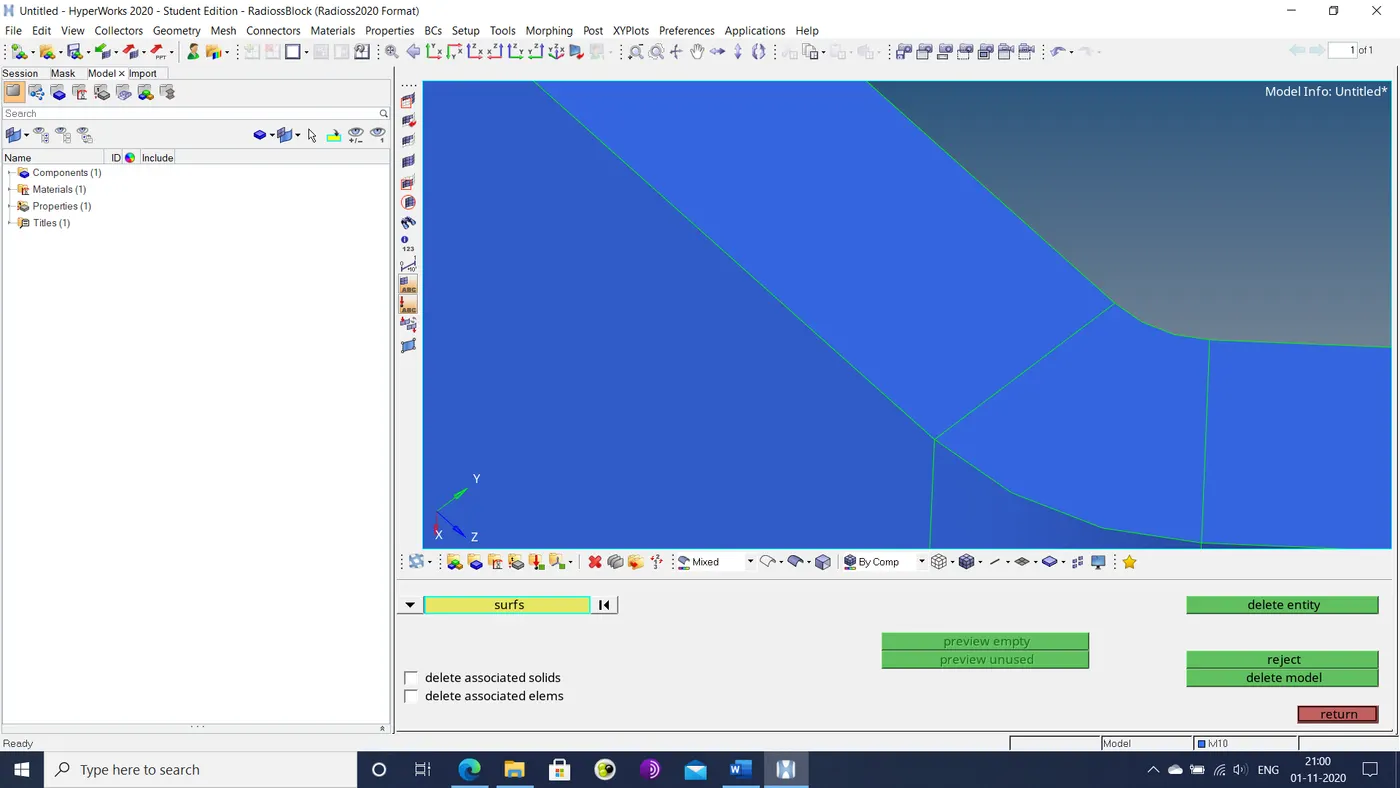
Figure 13: After removing extra face
- Overhanging surfaces are trimmed by the geometry>surface edit>trim with lines options, as shown below. The overhanging surface section is then deleted.
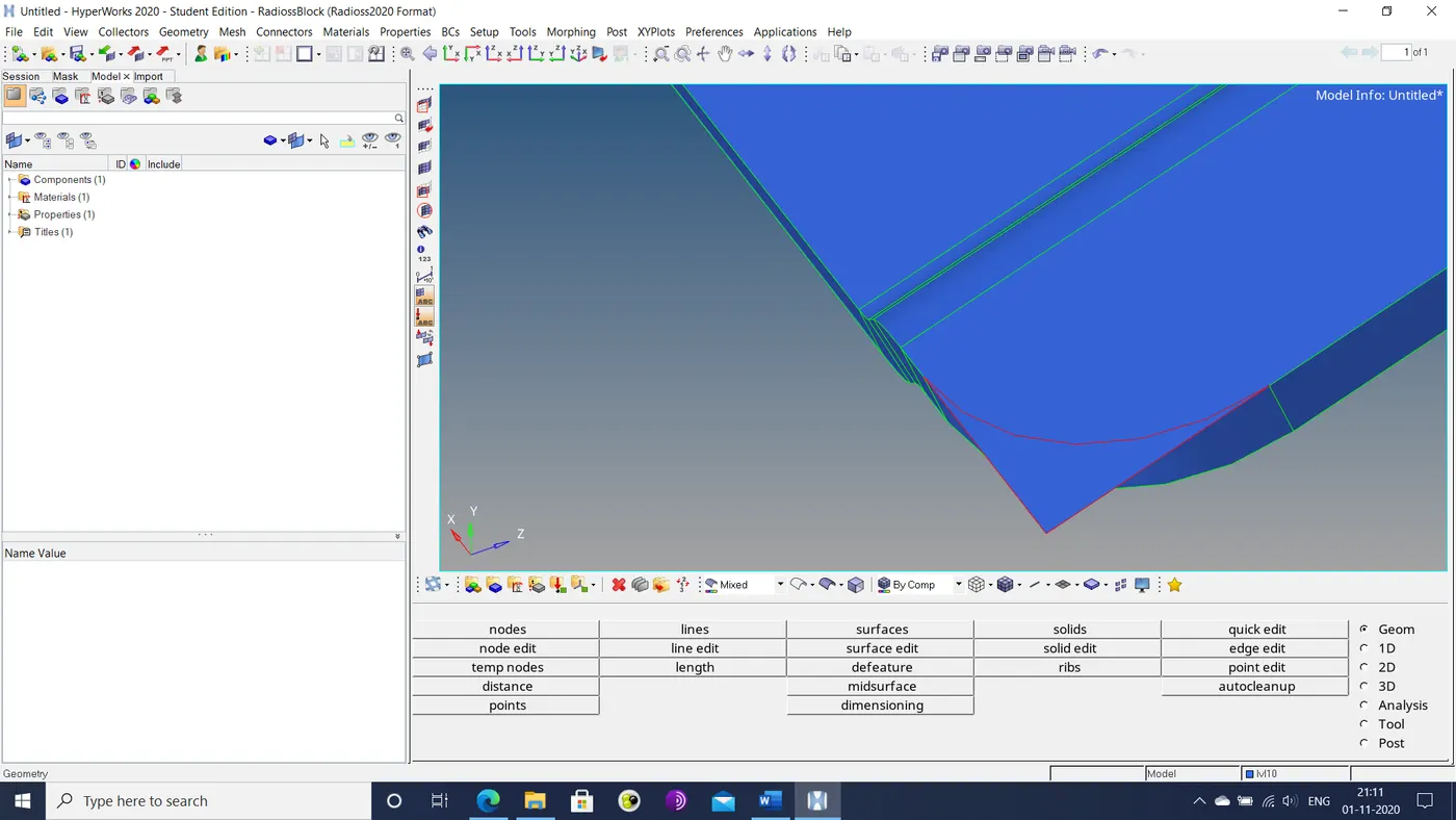
Figure 14: Overhanging face
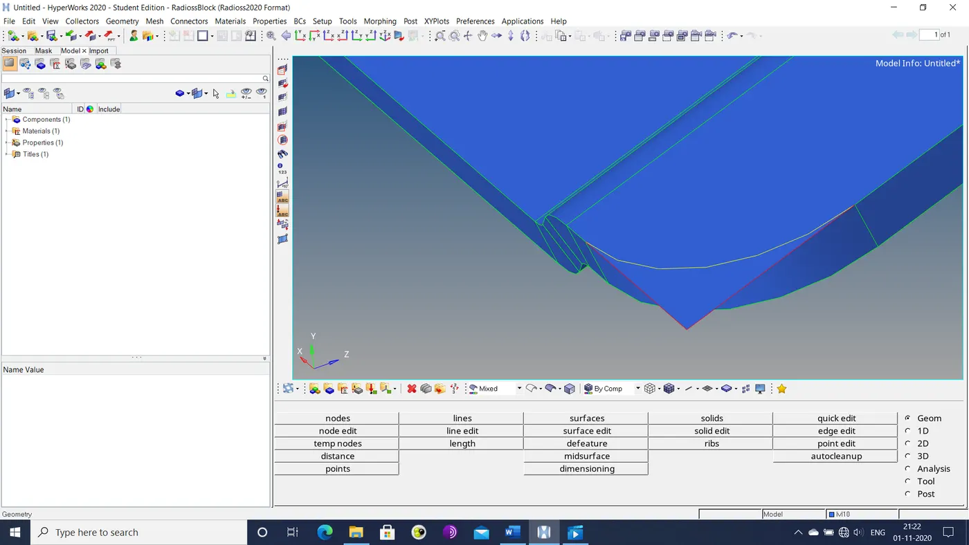
Figure 15: Trimmed face
- The mid-surface for the component is generated by the geometry>mid-surface option. The mid-surface generated is shown below.
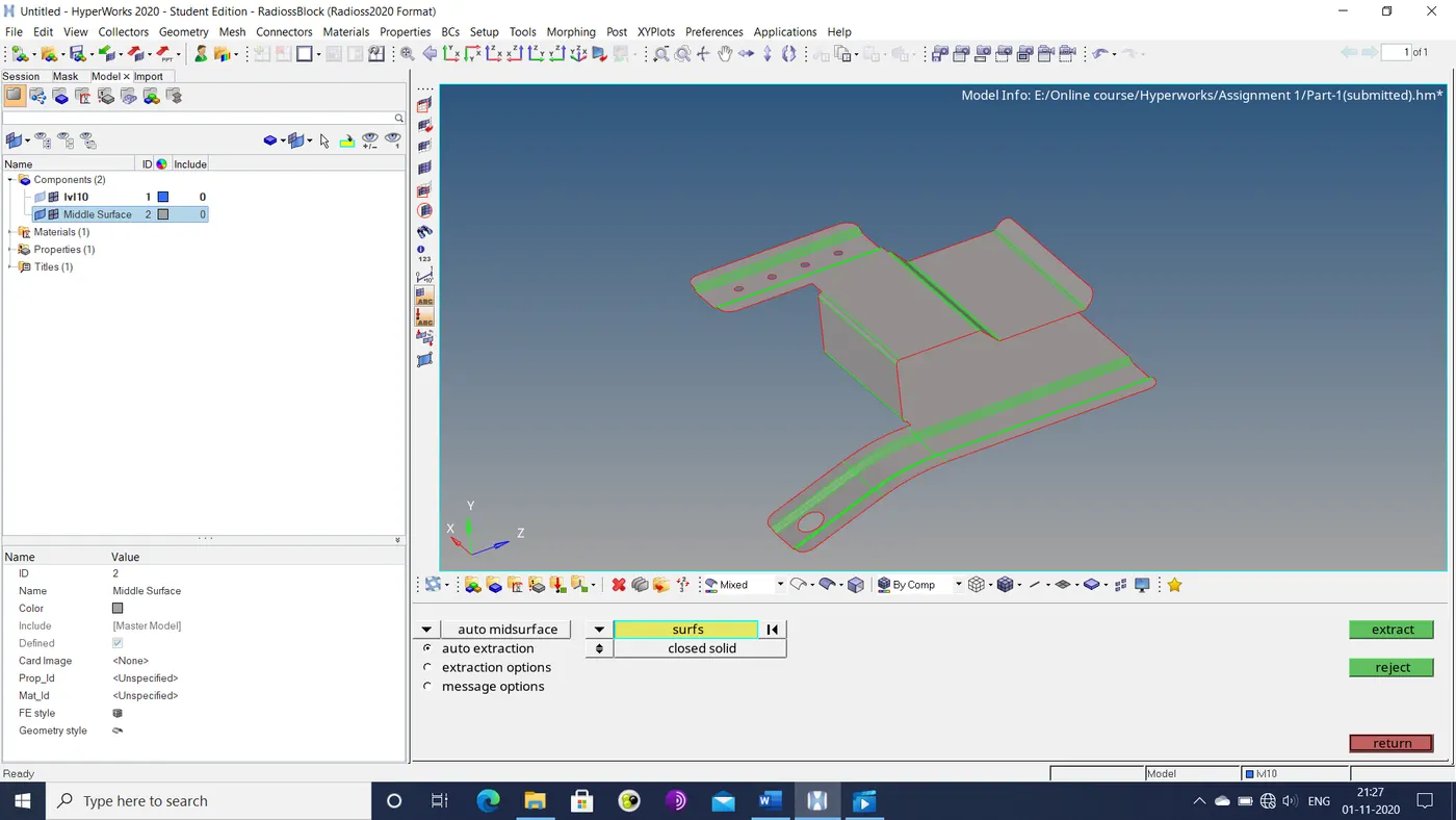
Figure 16: Resultant mid-surface
- Hole diameters are measured using the geometry>distance>three node option.
- If hole diameter is less than 5 mm, the hole is removed by the geometry>surface edit>un-trim option, as shown below.
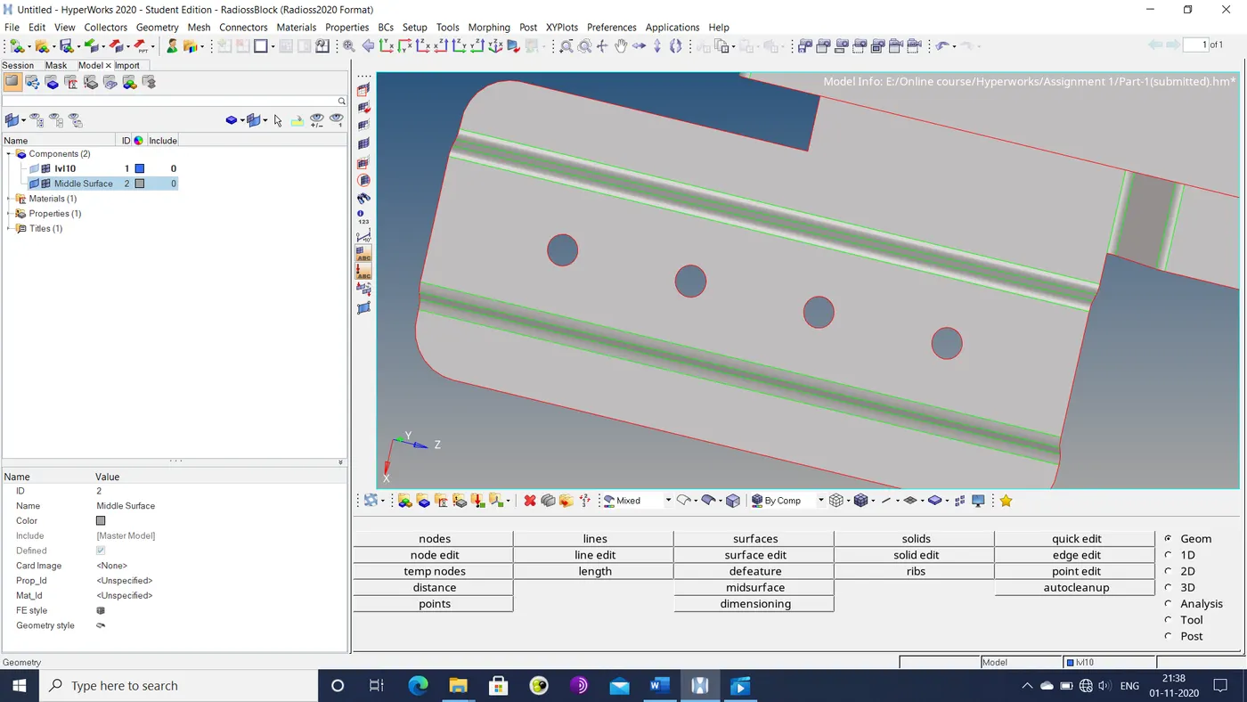
Figure 17: Holes before un-trim
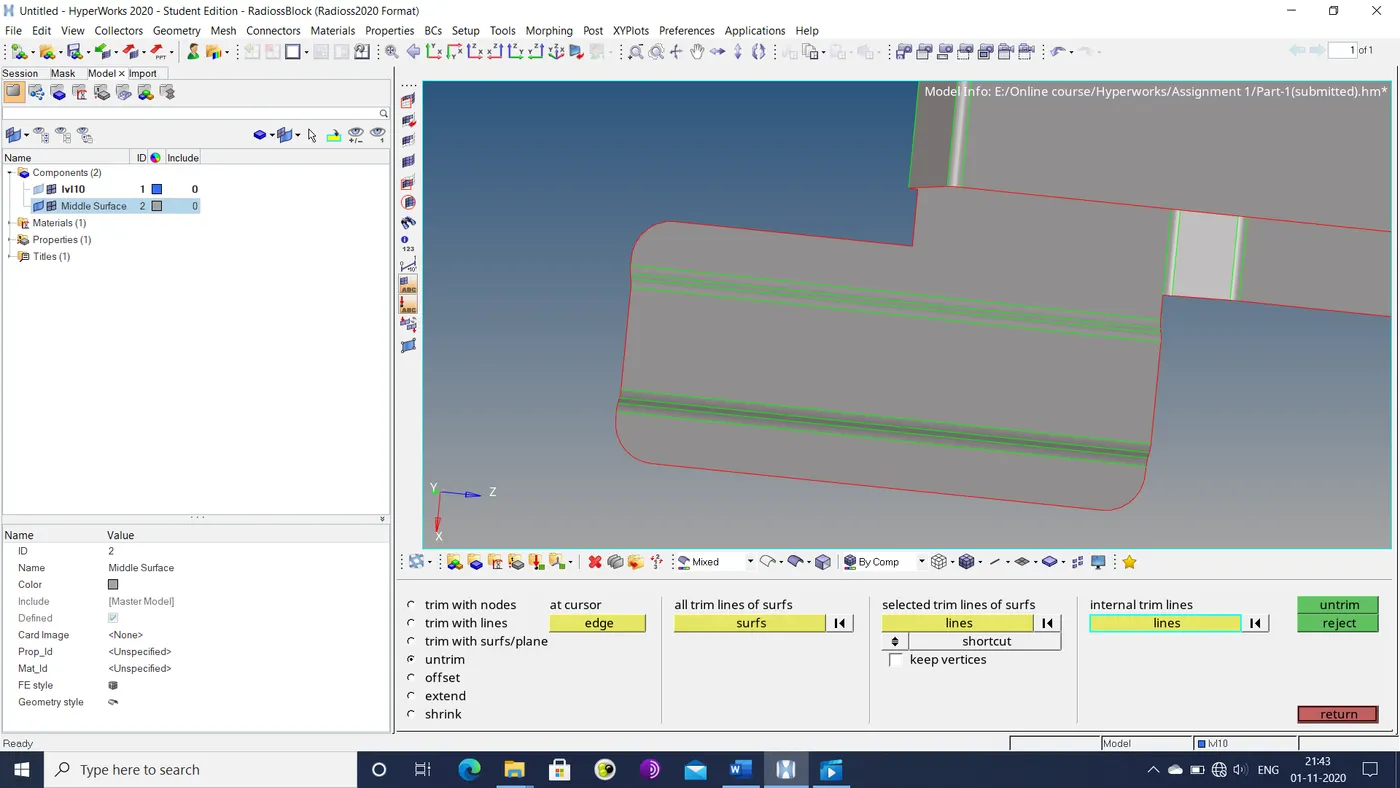
Figure 18: Removed holes
- Defeaturing of the mid-surface is performed by removing connecting lines via the toggle edge option, as shown below.
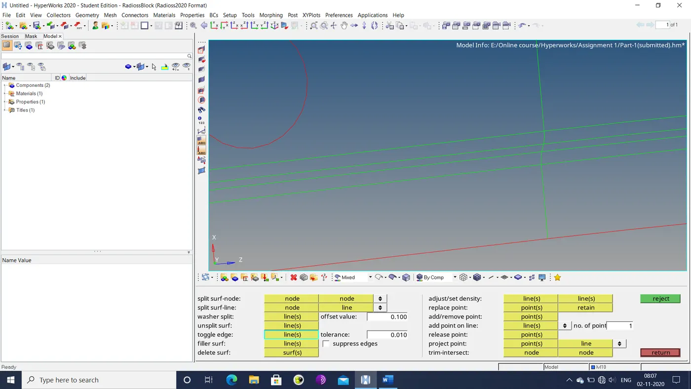
Figure 19: Before defeaturing
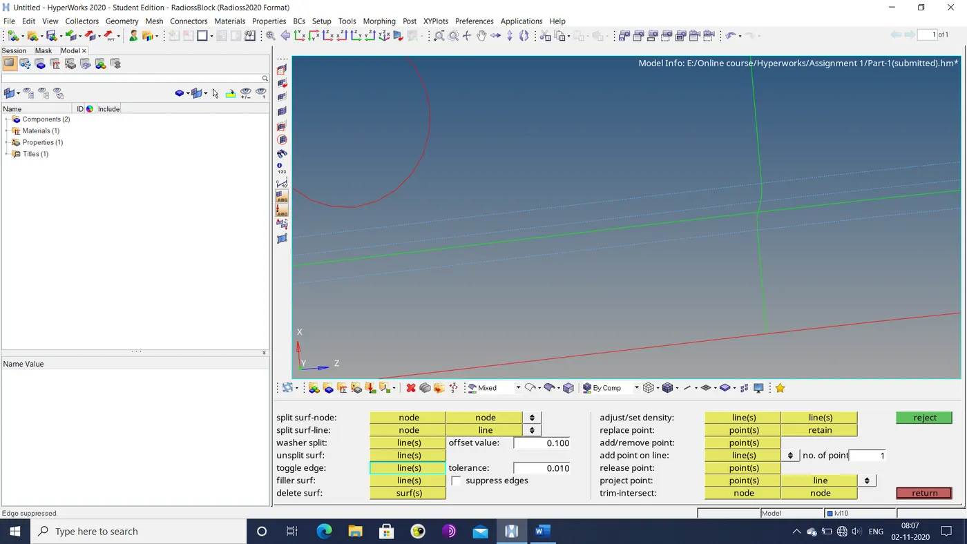
Figure 20: After defeaturing
- Corners are refined to meet quality criteria by the replace points option, as illustrated below.
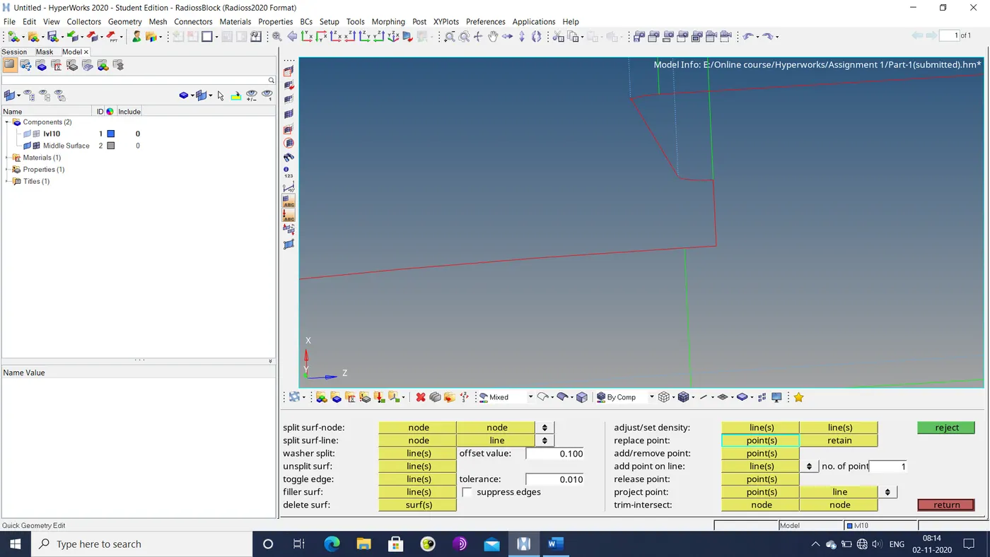
Figure 21: Corner before defeaturing
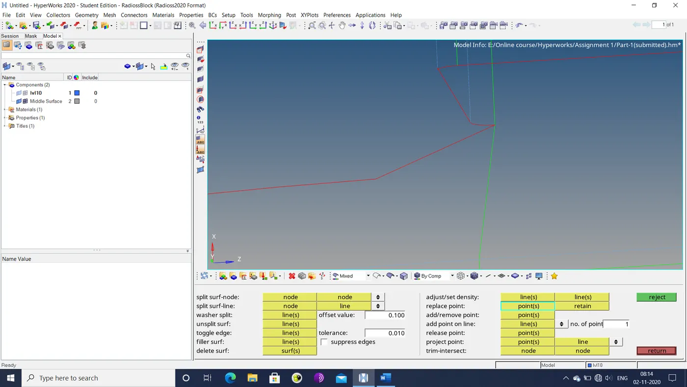
Figure 22: Corner after defeaturing
- The mid-surface is meshed section-by-section using the 2D>auto-mesh option, with a target length as illustrated below.
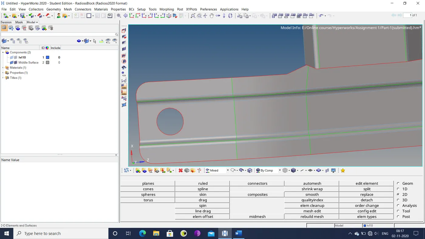
Figure 23: Surface before meshing
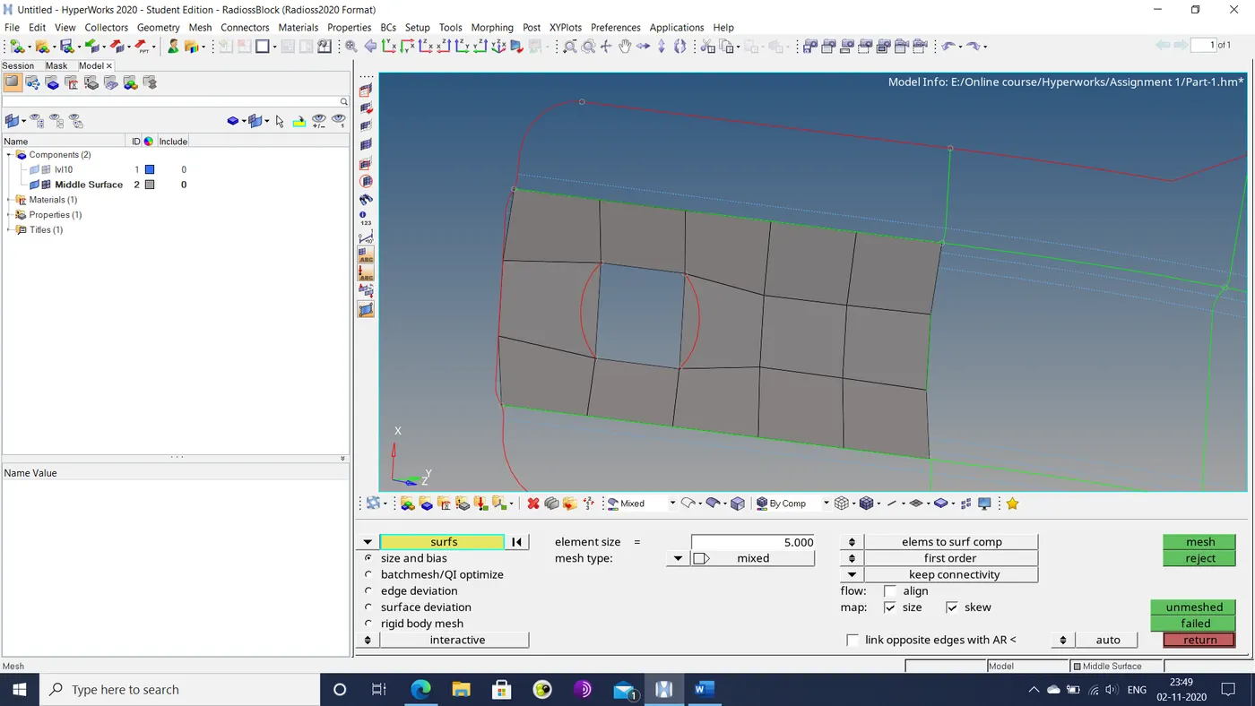
Figure 24: Meshed surface
- In edges where elements are not connected through their nodes, they are connected by hitting Shift+F3, and connecting discontinuous nodes, as shown below.
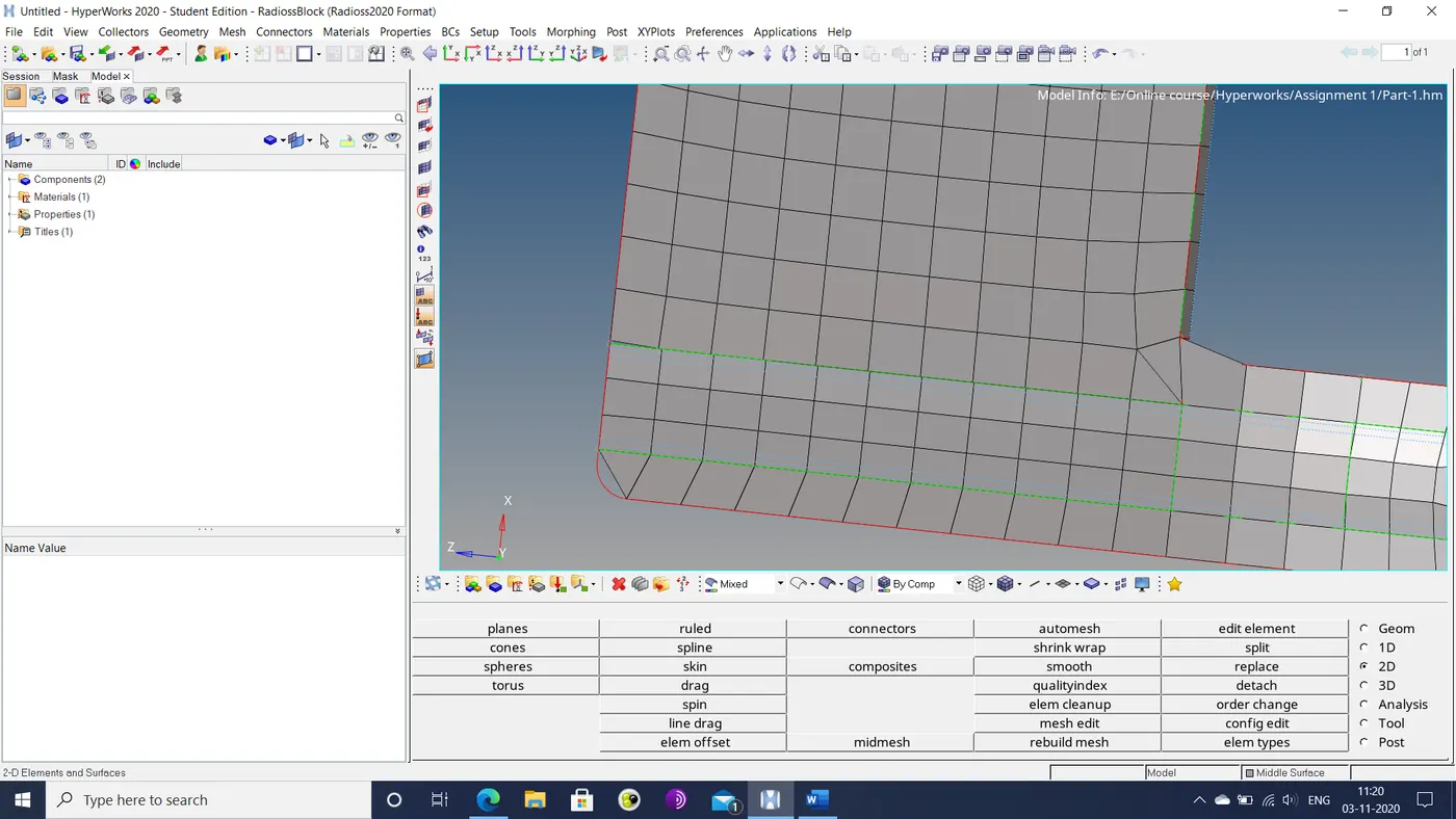
Figure 25: Misaligned nodes
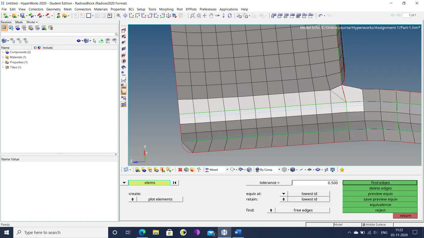
Figure 26: Aligned nodes
- The quality of the overall mesh is checked by the 2D>quality index option, to see if elements fit within the quality criteria of minimum element length (3.5 mm) and maximum element length (7 mm).
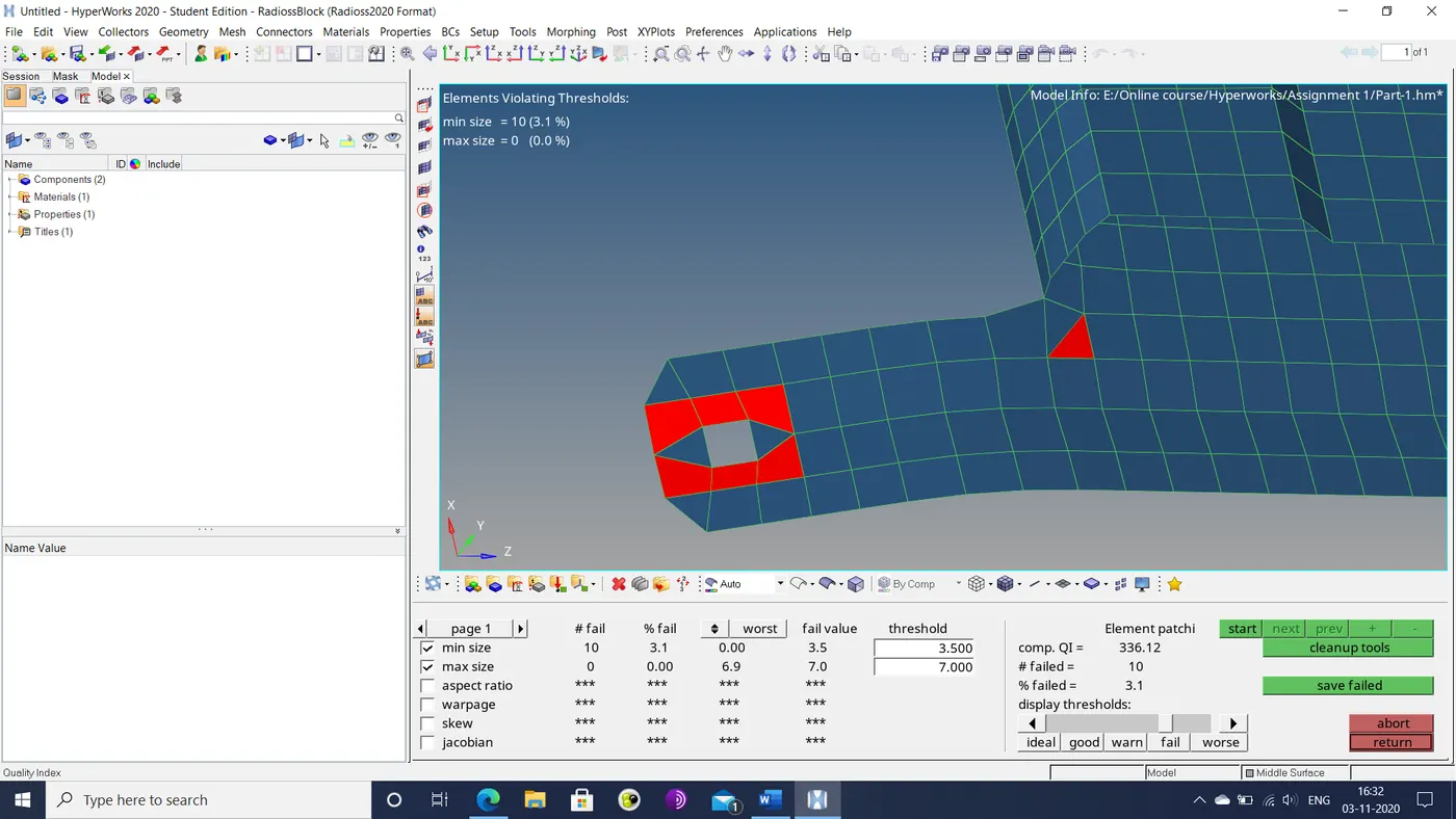
Figure 27: Quality of mesh
- The mesh is then improved by element optimize within the element cleanup tools, as well as the 2D>rebuild mesh option, as shown below.
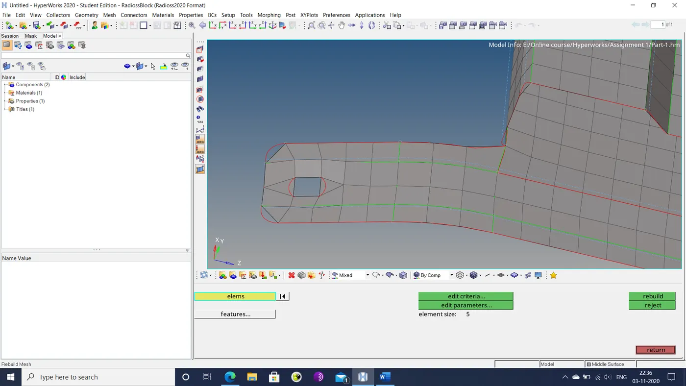
Figure 28: Fixed mesh
- The thickness property of the component is set to be 0.91 mm.
- The entire process is repeated for the two other components.
Additional images: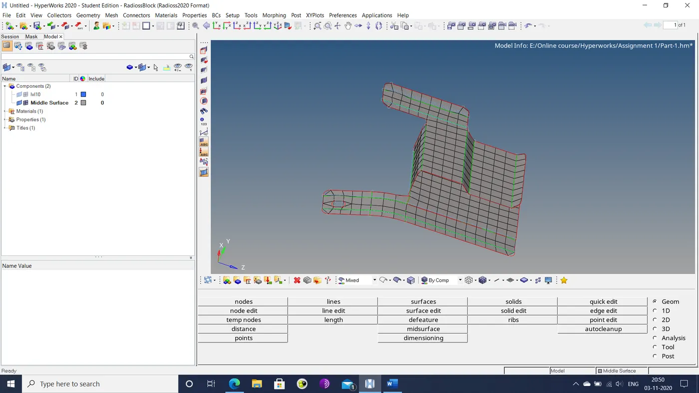
Figure 29: Final mesh for first component
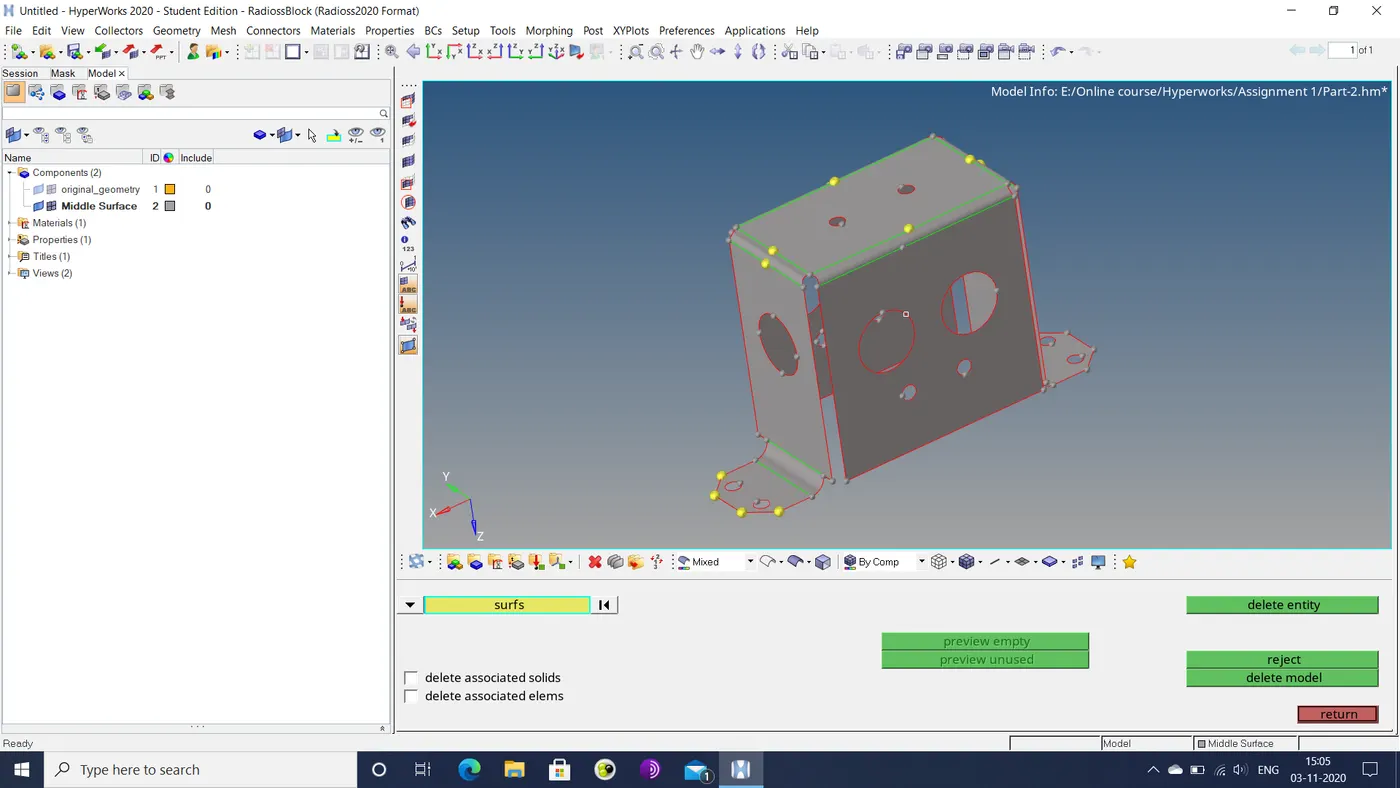
Figure 30: Mid-surface for second component
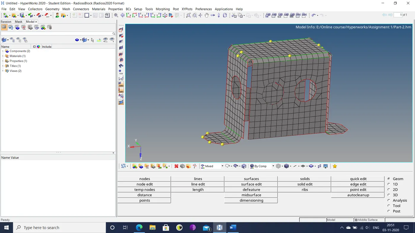
Figure 31: Final mesh for second component
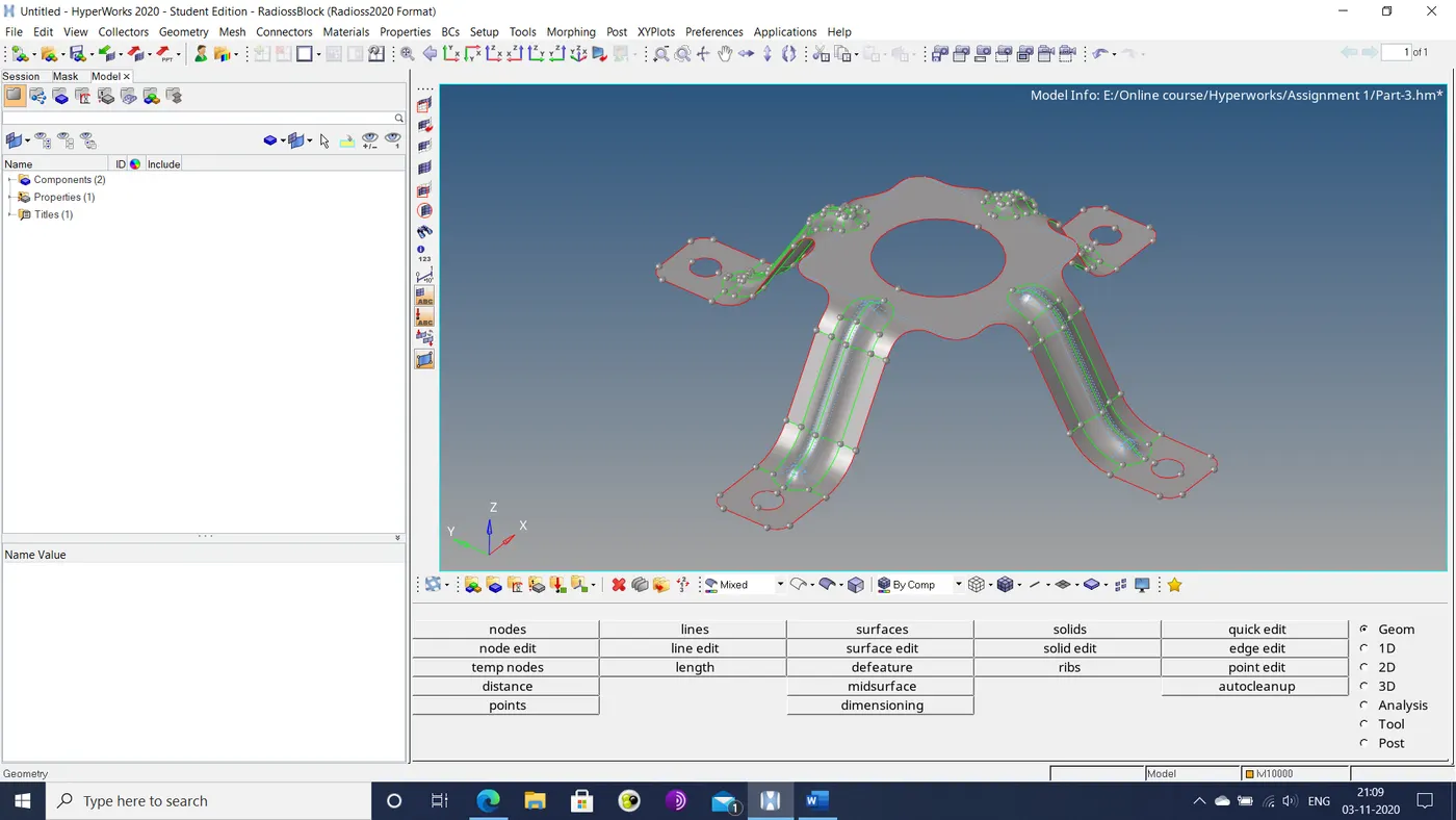
Figure 32: Mid-surface for third component
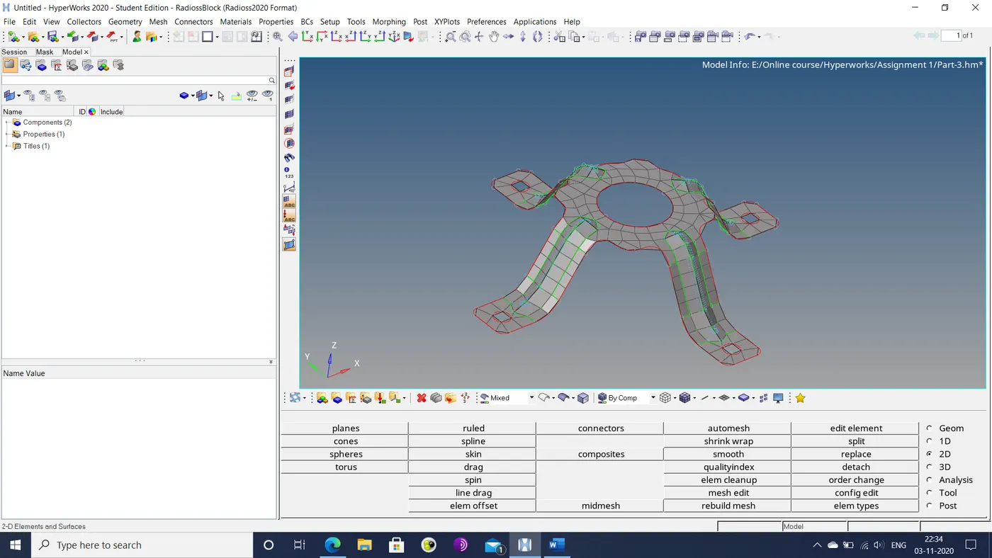
Figure 33: Final mesh for third component
Result: The three components had their mid-surfaces generated and meshed appropriately.
- The first component (Part-1) was easiest to operate on, owing to its rectangular profile. It had only one hole that needed to be modelled. This resulted in a mesh made almost entirely of quad elements.
- The mid-surface of the second component (Part-2) could not be properly generated. The greatest challenge in this assignment came from fixing the mid-surface generated. The repair involved recreating a couple of fillets between two surfaces. The symmetry of this component allowed for reflecting some sections of the mesh, thus cutting down on overall work.
- The third component (Part-3) had the most geometrically complex mid-surface that required considerable defeaturing. Quality criteria could not be met adequately at base holes, since they were large enough to need modelling and they were too close to a critical feature (a rib).
Conclusion: The assignment has been an exercise in the use of hyper-mesh for generating 2D FE mesh for given geometries.