Week 2 Air standard Cycle
Skill-lync project 1
Aim: The objective of this assignment is to create a Python code that can model the air standard cycle used in automobiles. The code is to compute the values of pressure & volume throughout the cycle and plot these values in a pressure vs. volume plot. The code is to also compute the energy output per cycle and the thermal efficiency.
Problem statement: The air standard cycle, or Otto cycle is the basic working principle of the internal combustion (IC) engine used in automobiles. The Python code created will use a number of input parameters to compute the values of pressures and volumes in this cycle and use these computed values to recreate the pressure vs. volume plot for the Otto cycle. The code will also compute the energy output and thermal efficiency from the given input.
The following are the input parameters referring to the combustion chamber, with their respective values used in this project.
- D1 (chamber diameter): 0.1 m
- L1 (stroke length): 0.1 m
- Q1 (combustion heat input): 1000 J
- Cr (compression ratio): 10
- Patm (atmospheric pressure): 101325 Pa
- Gamma (specific heat ratio): 1.4
- R1 (Specific gas constant): 287.058 J/(Kg*K)
Theory:
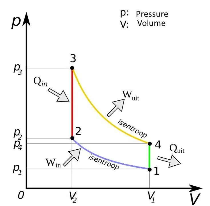 Figure 1: Pressure vs. volume plot of Otto cycle
As shown in the pressure vs. volume graph above, it is a series of 4 different thermodynamic processes that are listed below.
- The first process, representing the compression stroke of the IC engine, is an adiabatic compression process i.e., a process with no heat interaction.
- The second process, representing the fuel combustion, is a constant volume heat addition process.
- The third process, representing the power stroke, is an adiabatic expansion process.
- The fourth process is a constant volume heat rejection process. Ideally, this process would be followed by the exhaust and intake strokes with no net work done. Hence, those processes are not considered in the modelling of the cycle.
The pressures at the points 1, 2, 3 and 4 are given by the following expressions.
- P1 = Patm = Atmospheric pressure
- P2 = P1*(V1/V2)γ = P1*Crγ (Cr = compression ratio)
- P3 = P2*(V2/V3) + (γ-1)*(Q/V3) = P2 + ((Q*(Cr-1)*(γ-1))/VS) (Vs = Swept volume)
- P4 = P3*(V3/V4)γ = P3/Crγ
The pressure values throughout the curves 1-2 and 3-4 are given by the following expressions.
- P1-2 = P1*(V1/V1-2)γ
- P3-4 = P3*(V3/V3-4)γ
The volumes at the same points are given by the following expressions.
- V1 = V4 = Vs+Vc = Cr*Vs/(Cr-1)
- V2 = V3 = Vs/(Cr-1)
The thermal efficiency is given by the following expression.
Efficiency = 1-Cr1-γ
And the resultant work output per cycle is given by the product of efficiency and Heat input, i.e., W = Q*Efficiency
Procedure: The various lines of this created code are described below.
- The first lines of code are used to import the math, matplotlib and numpy modules.
- The next lines of code are used to define the various engine and operating parameters using standard SI units, as shown below.
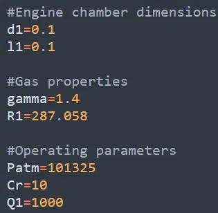
Figure 2: Constants defined for engine & operating parameters
- Swept volume is the next parameter to be derived using the engine parameters.
- The pressures & volumes at the 4 key points are then derived through the following expressions that are also listed in this report.
Figure 3: Expressions for pressures & volumes at key points
- Two arrays are created for the volume range in the compression and exhaust strokes, as shown in the screenshot below.
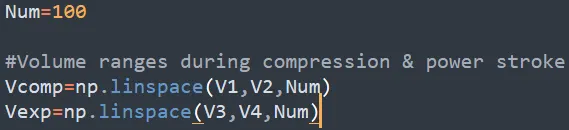
Figure 4: Definition of volume ranges
- Two empty arrays are created to store the computed values of pressure at curves 1-2 and 3-4. The respective values for these arrays are input using for loops, as shown in the screenshot below.
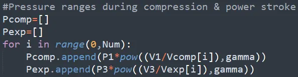
Figure 5: Computation of pressures during compression & power stroke
- The resultant curves are then plotted and the plot is saved in the local directory.
- The thermal efficiency is then computed by using its respective expression and then printed as a percentage.
- Finally, the work output per cycle is computed as the product of efficiency and heat input.
Results: The final code has been compiled below.
#Imported module
import math
import matplotlib.pyplot as plt
import numpy as np

#Engine chamber dimensions
d1=0.1
l1=0.1

#Gas properties
gamma=1.4
R1=287.058

#Operating parameters
Patm=101325
Cr=10
Q1=1000

#Swept volume
Vs=pow(d1,2)*l1*math.pi/4

#Pressures at key points
P1=Patm
P2=P1*pow(Cr,gamma)
P3=P2+((Q1*(Cr-1)*(gamma-1))/Vs)
P4=P3/pow(Cr,gamma)

#Volumes at key points
V1=Cr*Vs/(Cr-1)
V2=Vs/(Cr-1)
V3=V2
V4=V1

Num=100

#Volume ranges during compression & power stroke
Vcomp=np.linspace(V1,V2,Num)
Vexp=np.linspace(V3,V4,Num)

#Pressure ranges during compression & power stroke
Pcomp=[]
Pexp=[]
for i in range(0,Num):
	Pcomp.append(P1*pow((V1/Vcomp[i]),gamma))
	Pexp.append(P3*pow((V3/Vexp[i]),gamma))

#Final PV plot
plt.plot(Vcomp,Pcomp)
plt.plot([Vcomp[-1],Vexp[0]],[Pcomp[-1],Pexp[0]])
plt.plot(Vexp,Pexp)
plt.plot([Vexp[-1],Vcomp[0]],[Pexp[-1],Pcomp[0]])
plt.xlabel('Volume (m^3)')
plt.ylabel('Pressure (Pa)')
plt.savefig('PV_plot.png')
plt.show()

#Thermal efficiency and power calculation
Th=1-pow(Cr,(1-gamma))
Pout=Th*Q1
print(Th*100)
print(Pout)
It is effective in creating the Otto cycle plot as well as computing its thermal efficiency & energy output. Some of the defined variables, namely V3, V4, P2 & P4, turned out to be redundant, since the expressions for all the dependent variables did not use any of them. If required, the lines of code defining these variables can be omitted entirely.
The output pressure vs. volume is illustrated below.
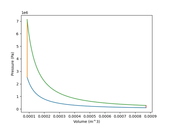 Figure 6: Final pressure vs. volume plot
It shows an accurate representation of the Otto cycle plot that captures the individual processes. The blue line represents the compression stroke, the orange one represents ignition, the green one represents the power stroke, and the red one represents heat rejection. The volume limits are in the ratio of 10:1 i.e., the compression ratio.
Finally, the thermal efficiency computed by the code turns out to be 60.19%. The energy output per cycle is 601.89 W, which is accurate as it is the product of efficiency (60.19%) and heat input (1000 W).