Assignment 4
Skill-lync assignment 4
Objective: The aim of this assignment is to demonstrate the role of material properties and the governing equations used to represent their physical behavior in the accurate simulation of a mechanical loading problem.
Case setup: The first set of starter and engine files (Named FAILURE_JOHNSON-000X) represent a circular membrane made of aluminum that is subjected to a mechanical load that is supposed to generate enough stress in the component to cause failure. The material behavior is governed by the equations under Law 2 (Johnson-Cook elastic-plastic behavior). A screenshot of the component is shown below.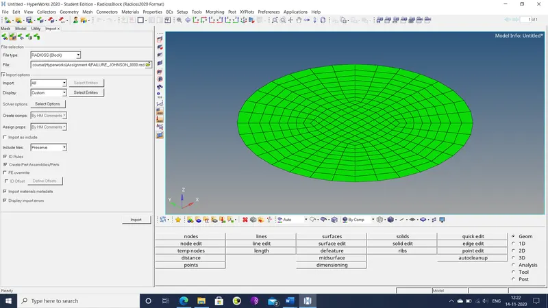
Figure 1: First component
The second component is exactly the same except for the governing equations (Law 27: Brittle plastic behavior) with different EPS failure values, as shown in the screenshot below.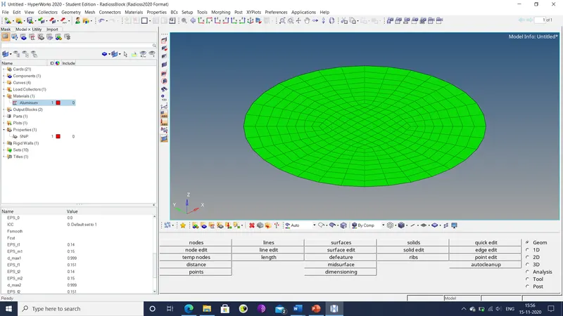
Figure 2: Second component and material properties
Procedure: The files are copied into 7 new files, each of which are worked on separately. The material properties are altered through the following sequence of steps.
- The starter file for the first component is imported into the hyper-works workspace. The FE element properties are already pre-selected for the most accurate simulation results.
- The simulation is run by the analysis>RADIOSS option. The resultant output files are exported to a separate file with the name Law2_epsmax_failure. The total simulation time was 82.48 sec and the number of cycles was 49380.
- The hyper-view workspace is opened up, where the .h3d file is imported and the simulation is animated.
- The window is split in two. In the second window, the hyper-graph 2D is opened, where the different types of energy histories are plotted, as shown below.
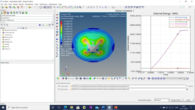
Figure 3: Resultant simulation result and energy plot
- The .out file is checked for the mass and energy error. Mass error here is 0%, while the hourglass energy error reaches a maximum value of 1.3 %.
- In a new hyper-works sessions, another copy of the first component is imported.
- In the failure properties, the following values are set for their respective parameters: - Ifail_sh=1, Dadv=1, Ixfem=1.
- Steps 2-5 are repeated and the resultant files are saved under the name Law2_epsmax_crack.
- In a third copy of the component, the failure property card is deleted entirely and the steps 2-5 are repeated.
- In a fourth copy of the component, the value of EPS_p_max is deleted and the failure property card is also deleted, and the steps 2-5 are repeated.
- In a fifth copy of the component, the governing equation for material behavior is altered. Here the governing law is changed to purely elastic behavior (Law 1), and steps 2-5 are repeated.
- The second component is imported into the hyper-works workspace. The element properties are then selected for maximum simulation accuracy. Then steps 2-5 are repeated.
- In another copy of the second component, the material property is altered, specifically the governing equations are changed to those under law 36 (Tabulated elastic-plastic behavior). Function used here is LOAD. The simulation is then run and results plotted like the previous cases.
- The various plots, run times and other outputs are compiled in a presentation.
Result: The various iterations of the given components provided vastly different outputs for the same scenario owing to the different material properties and governing laws used.
- The first case, titled Law2_epsmax_failure, had been setup with all the material properties for plastic behavior and most of the failure properties. A crack was created almost immediately that grew with time. This might be possible due to the low value of maximum plastic strain (0.151). As the component deformed further, it absorbed more strain energy until the stress levels reached critical levels and caused the component to break apart and generate a circular hole, as shown in the respective energy plot.
- The second case, titled Law2_epsmax_crack, had the failure properties altered so that shell elements that meet failure criteria are deleted. However, this did not cause any notable difference in the simulation results, other than material failure occurring later. The altered failure properties also worsened the hourglass energy error that reached unacceptable levels. However, since the plot shows almost no hourglass energy in the simulation itself, that may not be an issue.
- In the third case, titled Law2_epsmax_nofail, the failure card was deleted in its entirety. But the component behavior is still mostly identical to the previous cases. This may be due to the fact that the value of Eps_p_max (max. plastic strain) is still included in the material card. So, the material still failed when the strain in any area exceeded this value.
- In the fourth case, titled Law2, both the failure card and the value of Eps_p_max were deleted. This allowed for the elimination of material failure from the simulation. The energy plot reflects this as the energy level does not stagnate after a point, which normally signifies material failure and the relief of stress from the component. Due to this, the stress value increases further than in the prior cases.
- In the fifth case, titled Law1, the governing equations were changed to those under law 1, i.e. purely elastic behavior. With this material behavior, there was no material failure despite the inclusion of a failure card. This might be due to the fact that the failure card uses plastic strain values rather than elastic ones. The energy plot is a quadratic curve due to the purely elastic nature of the material. Essentially, the component is a perfect spring. Unlike the previous case, where the plastic behavior limited the amount of stress that can be generated, the mostly linear elastic behavior allowed for the maximum stress values to increase to nearly a hundred times greater than in the cases with failure.
- In the sixth case, titled Law27, the governing law was changed to law 27, i.e. brittle plastic behavior. The simulation of this case involved the greatest number of cycles. There was no obvious difference between the results here and those in the first three cases, aside from the subtle difference that the material cracked in a relatively clean manner.
- In the seventh and final case, titled Law36, the governing law was changed to that for tabulated plastic behavior. Here, the resultant energy plot and general material behavior was highly erratic with no clear pattern. This might be due to an improper selection of a function curve for the material card. The elements seemed to fail almost immediately, causing the component to seem to fall apart at the slightest application of stress.
Conclusion: Seven variants of the given components had their material properties worked on in order to demonstrate the difference in the behavior when said properties are altered.