Week 6
Aim: The objective of this assignment is to generate proper FE representations of connections in the given model such as bolts, welds, torsion bars, springs etc.. These entities are to be represented as constrained nodes, extended mesh etc..
Procedure: The procedure for creating the connections is catalogued below.
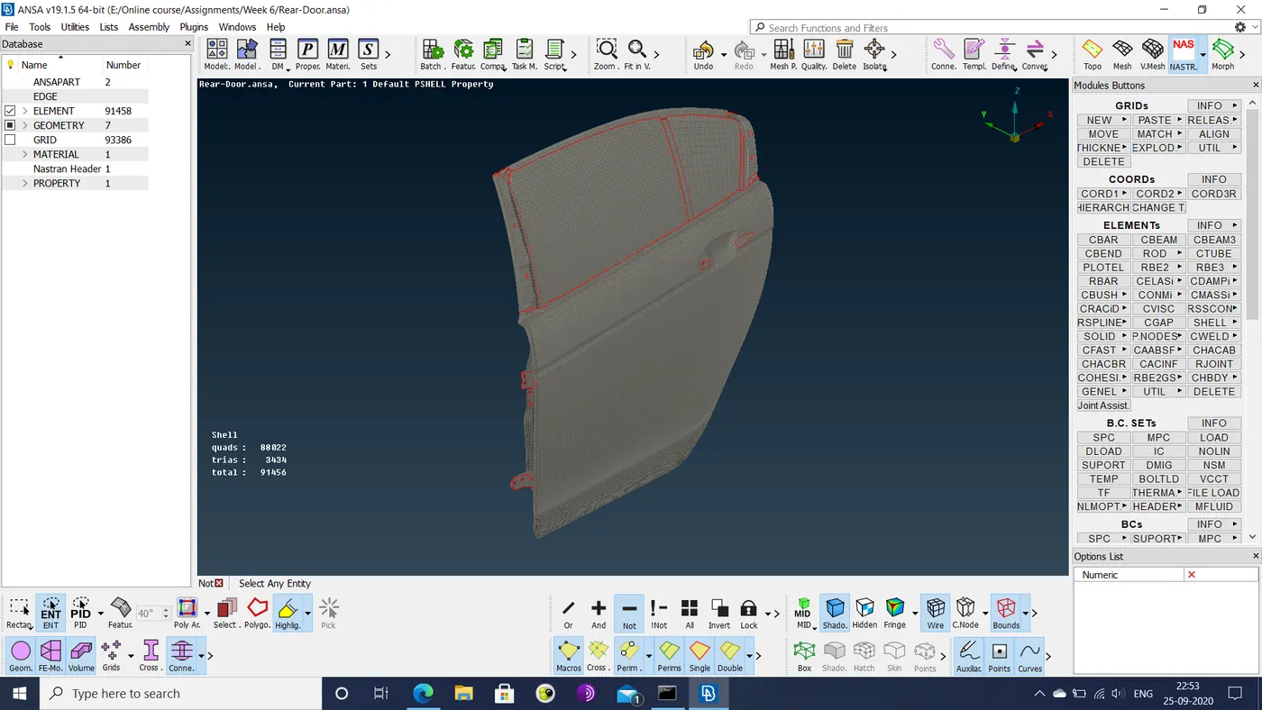
- The component is imported into the ANSA workspace in the following state.
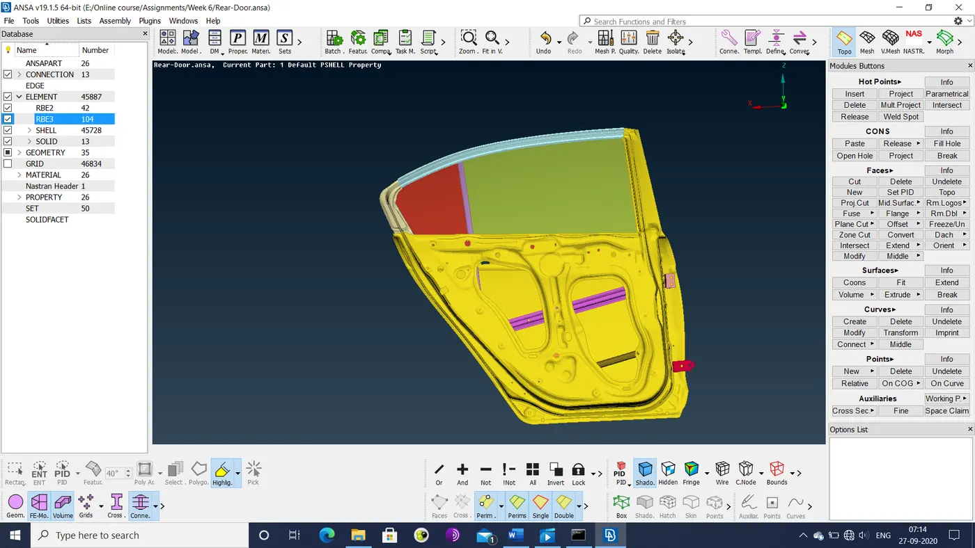
- The individual sections of the component are assigned individual part IDs in order to aid in making the required connections, as shown below.
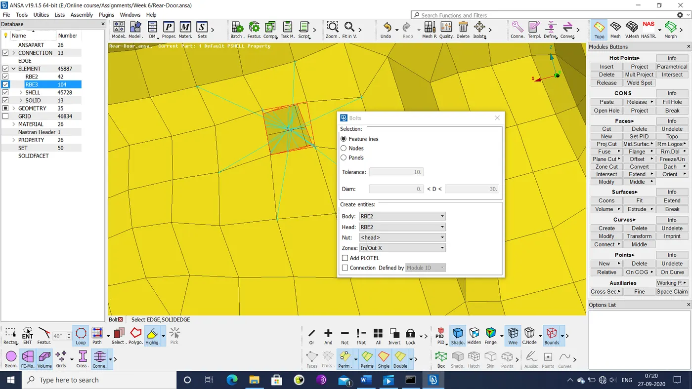
- Concentric holes are realized as bolt connections and represented using the bolt option as shown below.
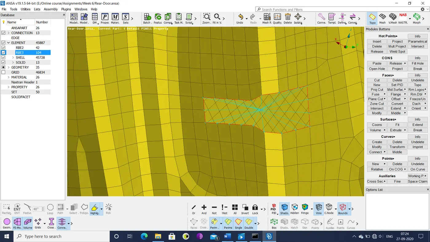
- The latch point of the door is represented as a constrained cluster of nodes by the ELEMENTs>RBE2>Many nodes option in the NASTRAN deck, as shown below.
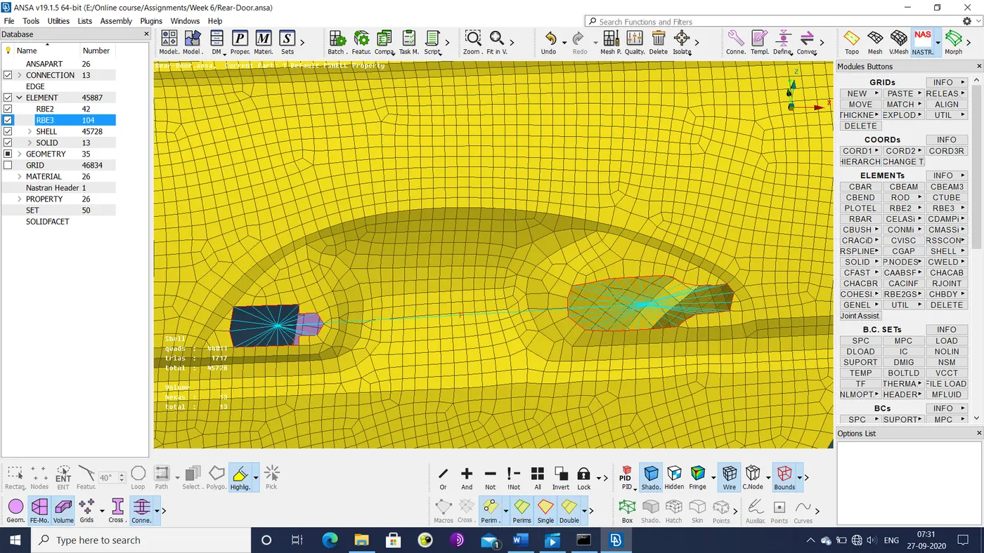
- The door handle is represented as a 3-node RBE2 cluster between 2 RBE2 clusters, as shown below.
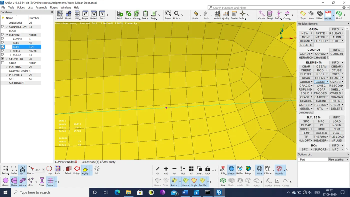
- A mass of 100 grams is assigned to the handle using the ELEMENTs>CONMi>CONM2>Nodes option.
- The bolts connecting the hinges are represented by the bolts option, but with the DOF flag for z-axis rotation (no. 6) disabled.
-
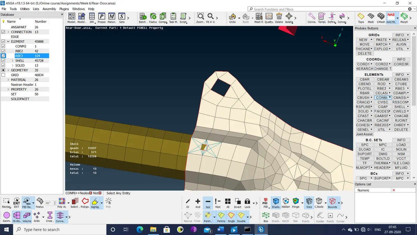
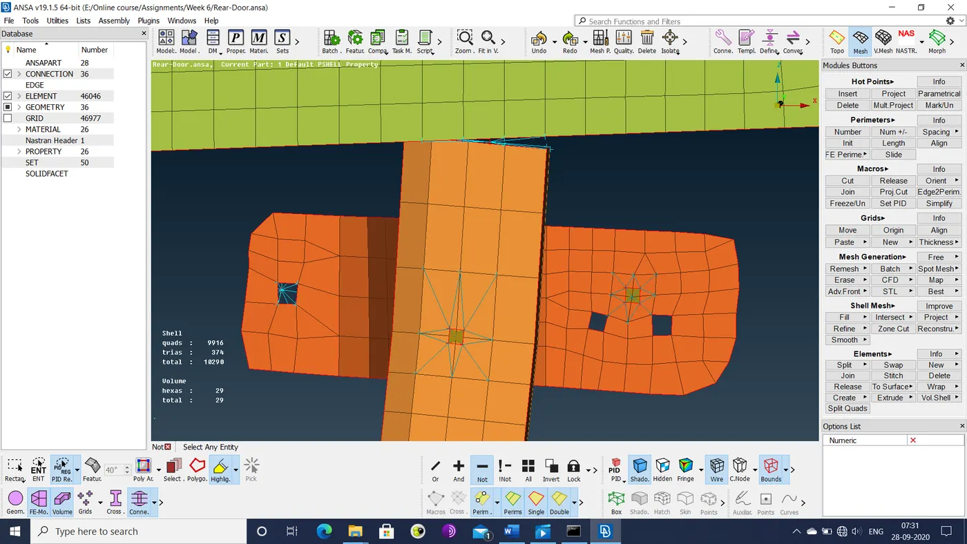
Spot welds are defined by converting 3D points on one of the parts into a spot weld, followed by assignment of RB3-HEXA elements between the welded sections using the connection manager, resulting in the following mesh pattern.
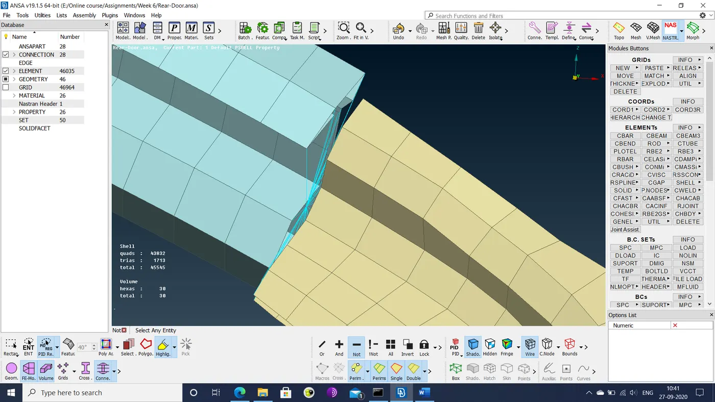
- Any other section pairs that cannot be joined by either spot welds or bolts are connected via RBE2 cluster nodes, as illustrated below.
- The window sliding arm is extended up to the window via the grids>MVFree option, followed by reconstruction of the mesh on the extended arm. The end of the arm is then connected to the window via RBE2 cluster nodes, resulting in the following geometry.
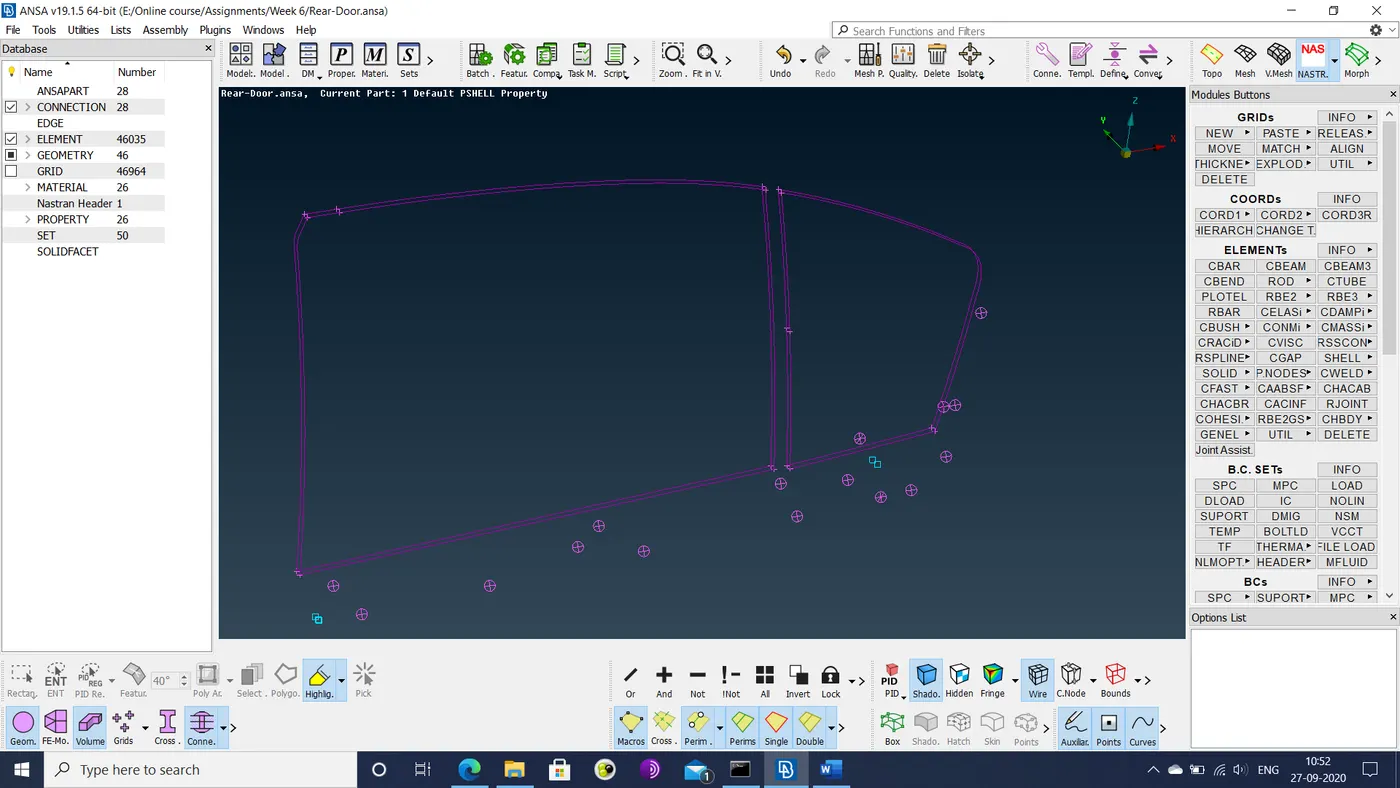
- For the windows, connections are based on curves generated from the window boundaries. These curves are generated using the Perimeter>Feat2curve option in the mesh deck. They are then converted into 2 curves on either side of the window using the transform>copy and move option. The resultant curves are shown below.
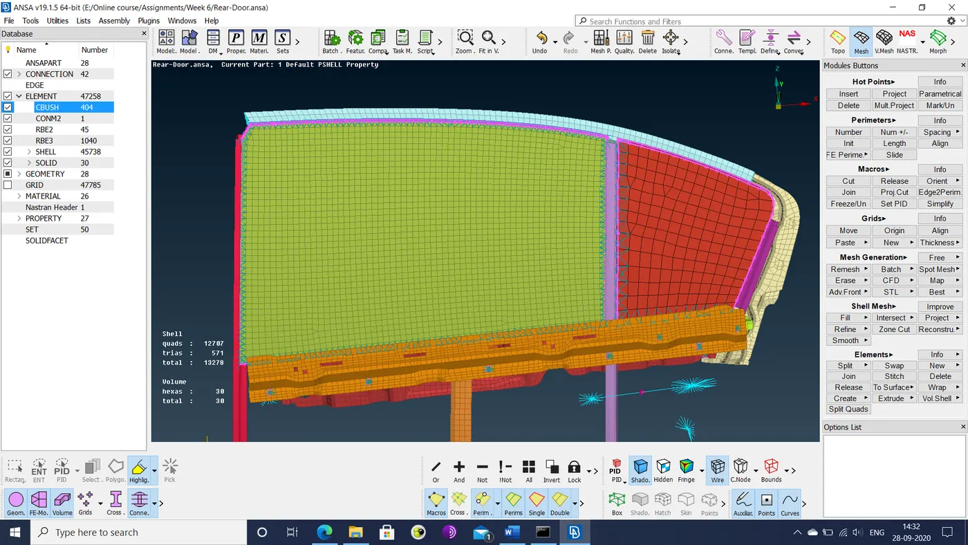
- The curves are then converted into spot lines. Using the connection manager, these spot lines are used to connect the window to the frame. The RBE3-CBEAM elements are assigned to the connection and their coordinates are aligned with the global coordinates. The final mesh is shown below.
Learning outcomes: The process of connecting parts together has proven to be a fairly straightforward exercise of identifying concentric holes and surfaces in close proximity, with some care being required in things like correct type of connections and part IDs and properties.
- In order to make connections with defined properties, i.e. those that require the aid of the connection manager, it is imperative that the connected parts have their own distinct part IDs. The imported geometry did not have these distinctions. Thus, a significant amount of time had to be spent defining these PIDs for their respective sections.
- Bolts were easy to define. Making these connections requires identification of concentric holes. At the hinge section, the DOF for rotation about the z-axis (no. 6) is unconstrained.
- Spot welds are required at areas where 2 or more surfaces are in close proximity to each other. Care needs to be taken in the sequence in which the surfaces are selected, starting from the stiffest, along with the correct type of mesh element being used to represent the spot weld. One region proved to be problematic (upper stiffening bar connection), where the weld was being applied to the wrong side of the bar section, owing to the folded sheet metal door panel it was connected to.
- Windows were trickier as that required consideration of element length and local coordinate alignment. Some connections in these windows (such as the curved edge of the rear side window) could not be created for unknown reasons.
- RBE2 cluster nodes are the default option for connecting sections that don not have concentric holes, nearby surfaces or any criteria that can qualify it for any of the connection types. They can be used to rigidly connect virtually any section. However, properties and DOFs for these nodes cannot be defined.
Conclusion: Application of a variety of connections were practiced in this assignment. The given model allowed for practicing connection of parts via bolts, spot welds, rubber bushings and basic rigid constraints.