Week 5
Skill-lync assignment (week 5)
Aim: The objective of this assignment is to generate a 3 dimensional FE mesh for the given component that meets the quality criteria for geometry and element length.
Procedure: The given component is meshed through a sequence of steps that are listed below:-
- The CAD geometry of the component is imported into the ANSA workspace in the following state.
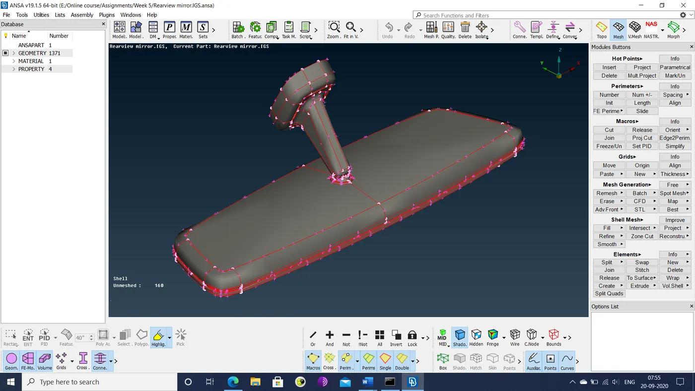
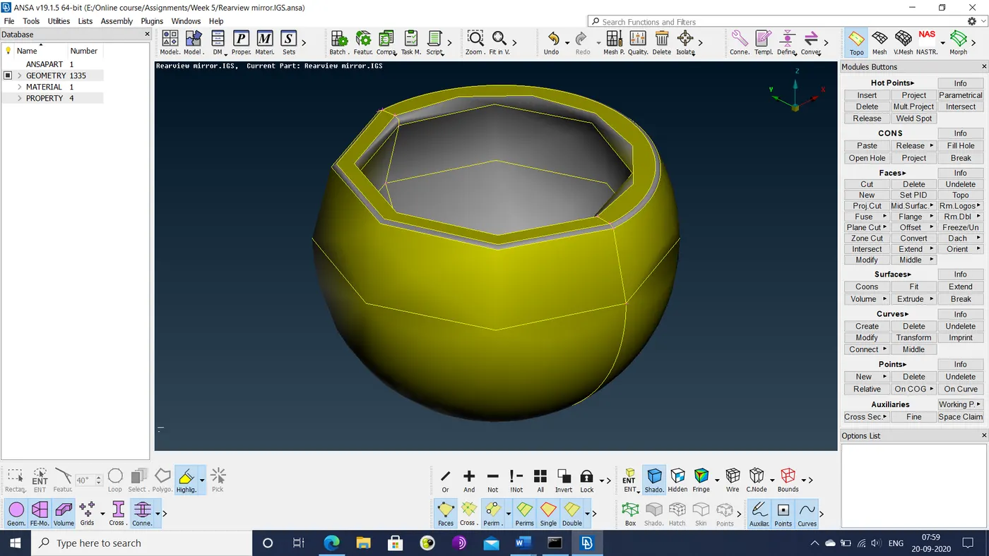
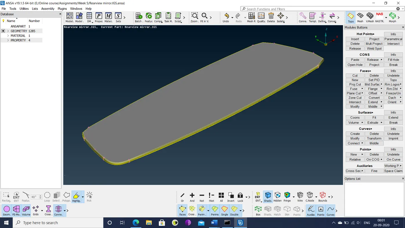
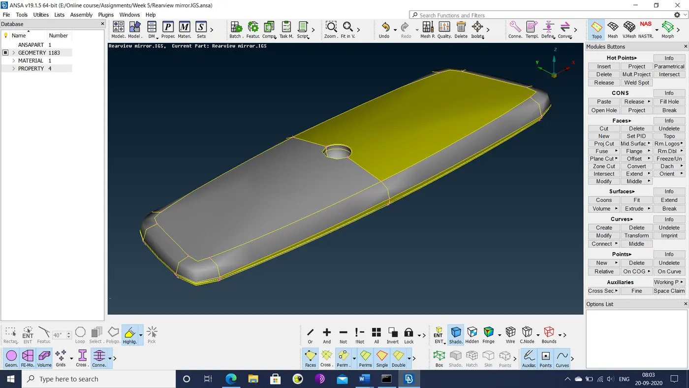
- The individual sections of the component are worked on using the topo option. After a geometry check for errors, the fixed geometries are created as shown below.
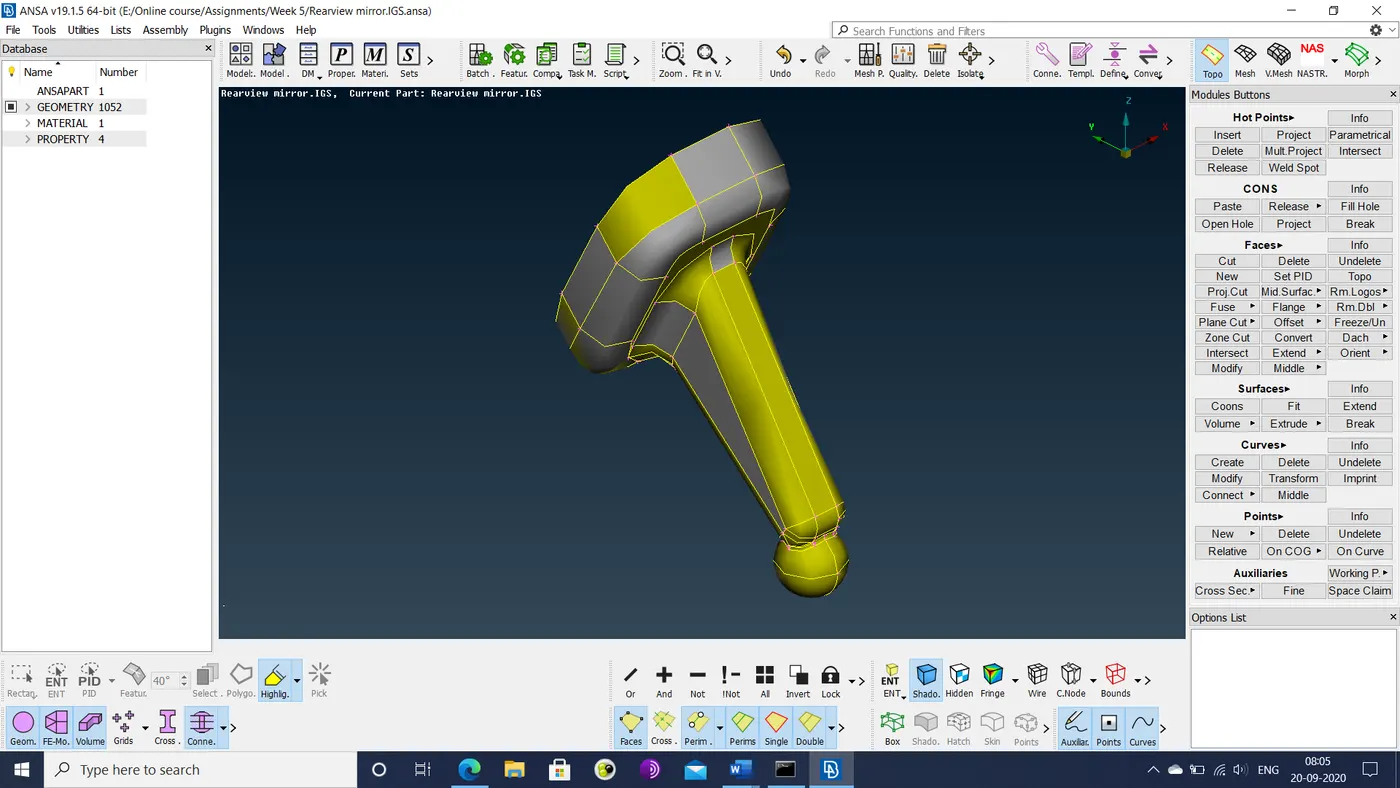
- The following mesh quality criteria are set.
|
S.No |
Quality Criteria |
Value |
|
1 |
Target/Average length |
1 |
|
2 |
Minimum Length |
0.5 |
|
3 |
Maximum Length |
2 |
|
4 |
Tet-collapse |
0.2 |
- Distance between cons are checked. If some cons are located such that resultant mesh elements would violate quality criterion of minimum length at that region, defeaturing is performed at that region. In some cases like fillets, such cons are removed entirely using the macros>join option.
- Shell mesh is cast over the surface of each section. Curved regions such as fillets are meshed with ortho triangular elements.
- Flat regions are meshed with triangular elements.
- Mesh flow is improved through the reconstruct option.
- Once a section’s surface is fully meshed, the volume enclosed within is defined using the volume meshing module’s volume>define option.
- The volumetric mesh is generated using the tetra-FEM option.
- After the mesh is generated, it is checked for qualities of element length and element collapse.
- The surface of the volumetric mesh is checked for kinks or peaks.
- Since there are no such errors or flaws in this mesh, the process is complete.
Learning outcomes: Tetra volume meshing is a far easier exercise than shell/mid-surface meshing. Quality criteria are much less restrictive. This reduces the amount of defeaturing and mesh refinement required. Unlike the previous assignments, this one took far less time to complete (about 4 hours). This could be partly due to the simple geometries of the component sections. Overall time could potentially have been even less if batch meshing was used to generate the surface mesh rather than by manual method. While element lengths were occasionally too low (eventually rectified), collapsed elements, kinks or peaks in the volumetric mesh never arose. So rectifying these errors could not be practiced.
Conclusion: The tetra meshing process was demonstrated in this assignment. Volume mesh for each of the component’s sections were generated quickly. Thus tetra mesh is useful for quickly generating a mesh over a complex 3 dimensional geometry.
Google drive link: https://drive.google.com/file/d/1eNwUr6OO36to4stu7951sbVXw8KxC9H9/view?usp=sharing