Week 6-Meshing of Hood Challenge
Skill-lync assignment (week 6)
Aim: The objective of this assignment is to create representative mid-surfaces for the given components and to create 2D shell meshes for them as per the given criteria.
Case setup: The component is a complete model of a car bonnet, as illustrated below.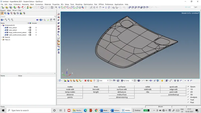
Figure 1: Complete hood model
It is comprised of a total of 5 separate parts that include an upper & lower panel, 2 hinge plates and a latch plate. It is to be meshed as per the following quality criteria: -
Table 1: Quality criteria for 2D shell mesh
|
S.N |
Quality Criteria |
Value |
|
1 |
Aspect Ratio |
5 |
|
2 |
Skewness |
45 |
|
3 |
Warping |
15 |
|
4 |
Taper |
0.5 |
|
5 |
Min. Length |
2 Units |
|
6 |
Max. Length |
8 Units |
|
7 |
Min angle Quad |
45 |
|
8 |
Max angle Quad |
135 |
|
9 |
Min angle Tria |
20 |
|
10 |
Max angle Tria |
120 |
|
10 |
Tria % |
10 |
Procedure: The components are worked on through the following sequence of steps: -
- The component geometry is imported into the Hyper-works workspace.
- The preferences>criteria file settings menu selection is then used to input the necessary quality criteria.
- The latch section is isolated and its mid-surface is extracted, as shown below.
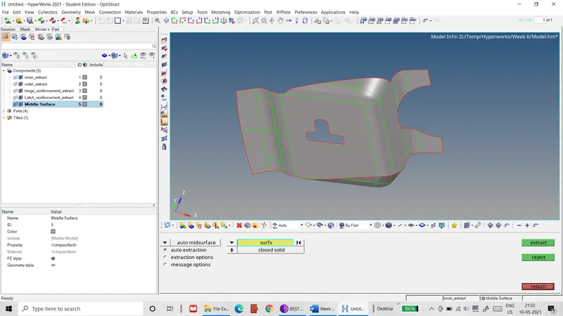 Figure 2: Mid-surface of latch section
- The mid-surface is checked for geometric errors and unnecessary edges & fillets are removed by the Geom>defeature tab. The hole in the middle of the component is given a washer split 5 units wide.
- The latch mid-surface is set as current, so that the mesh generated for it is associated to it. The 2D>automesh tab is used to create the mesh for the component, starting from the washer section. The mesh is rebuilt and edited by a combination of aligning nodes and smooth operation to generate the washer mesh, as shown below.
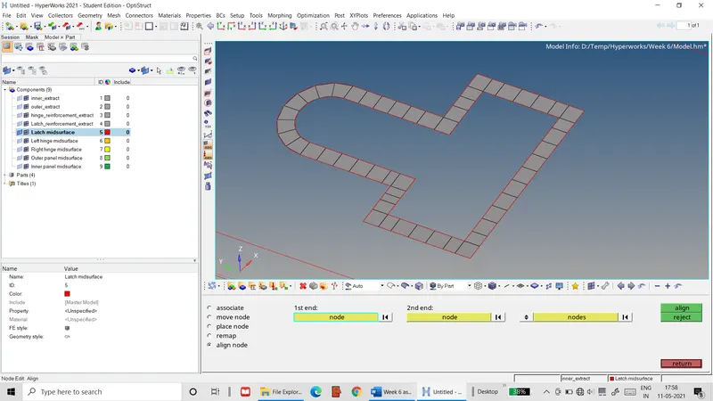 Figure 3: Mesh generated for washer region
- The remaining mid-surface is meshed section-by-section. Each time the mesh is checked for element quality through the use of the 2D>qualityindex tab. Whenever the overall mesh is inadequate, it is rebuilt using the 2D>rebuild mesh tab. If the rebuild mesh tab is not enough, the mesh is manually edited using the clean-up tools in the qualityindex tab.
- A final check is performed for the element normal vectors and the free edges by the Tool>normals and the Tool>edges tabs.
- After the mesh is completed for the mid-surfaces, the other parts & components are deleted and the file is saved.
- In a new Hyper-works session, the original file is imported and the left hinge section is selected for mid-surface and meshing.
- Steps 3-8 are repeated for the left hinge section.
- Steps 3-8 are repeated again for the remaining sections.
- For the inner & outer panel sections, half of the section is meshed on one of their symmetric sides. The resultant elements are then duplicated and reflected onto the side using the Tool>reflect tab. The elements at the boundary of the symmetry plane are connected together using the equivalence option in the Tool>edges tab.
Result: The final meshes for the various sections are listed below.
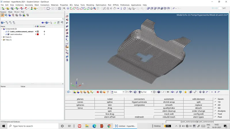 Figure 4: Final FE mesh of latch reinforcement section
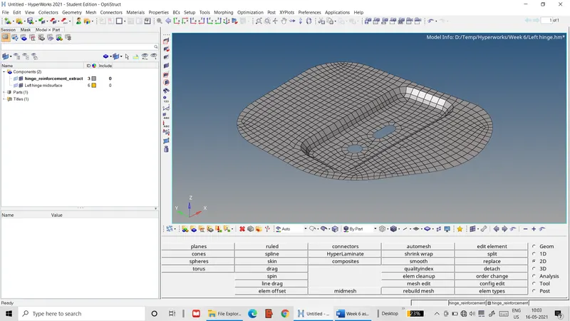 Figure 5: Final FE mesh of left hinge reinforcement section
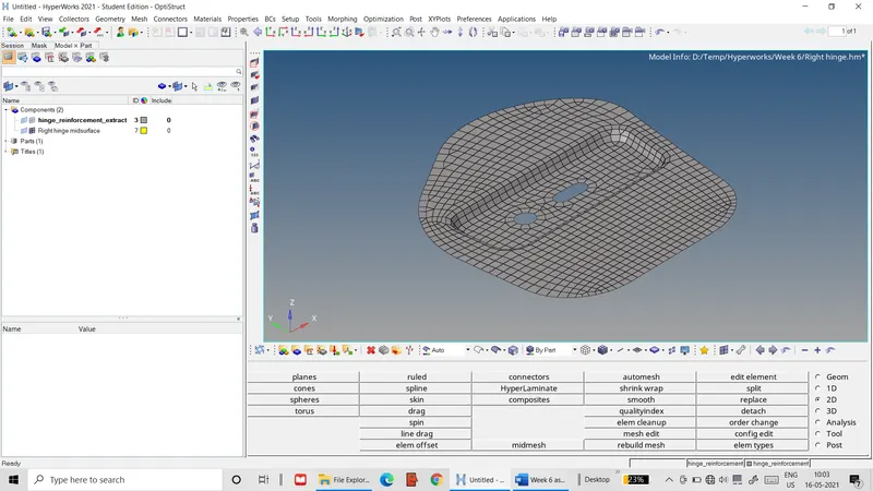 Figure 6: Final FE mesh of right hinge reinforcement section
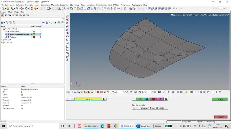 Figure 7: Final FE mesh of outer panel
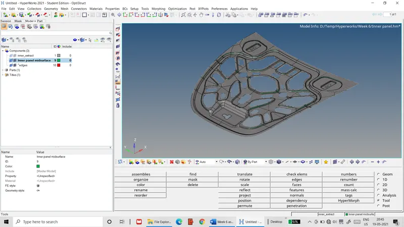 Figure 8: Final FE mesh of inner panel