Assignment 2
Skill-lync assignment 2
Aim: The first objective of this challenge is to calculate the properties of speed of sound and time for sound to travel component from the given engine file and then to edit it so that it can generate time scale and animation as specified. The final objective is to generate a 3D FE mesh for the given components.
Case setup: The .rad files provided are a starter file and n engine file for a rail component made of steel material.
The first component is a combination of a cover and a hub, with the hub having already been surface meshed, as shown below.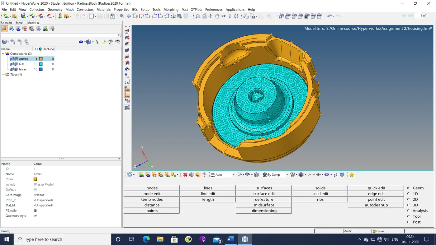
Figure 1: Cover and hub assembly
The second component is an arm bracket with the following geometry that is divided into 4 sections.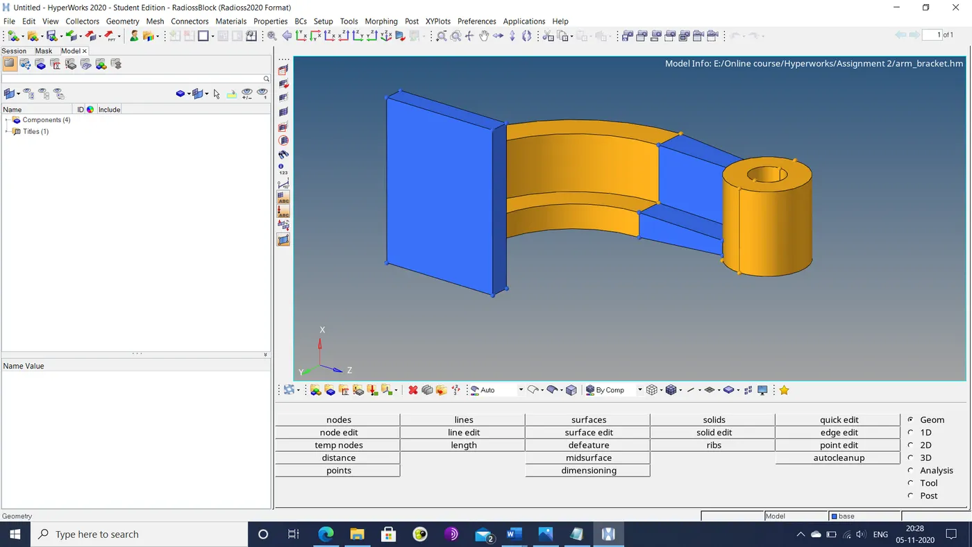
Figure 2: Arm bracket
The geometry has been divided into 4 sections that are combined to form one.
Q & A: In the given component, the values for Young’s modulus ( E ) and density (ρ) are 210000 MPa and 0.0078 g/mm3.
- From these values, the speed of sound in the steel can be found by the formula c=Sqrt(E/rho)Thus, the speed of sound is 5188 m/s or 18679 km/hr.
- The length of the rail is 1000 mm or 1 m. Sound and a shock wave are essentially the same. So, the time taken for both to travel the length of the rail are derived by dividing the distance by the speed of sound. Thus, this time taken is calculated to be 0.193 ms.
Procedure: The engine file is edited as described in the assignment statement.
- At the /RUN section, the termination time is set to the time calculated above, i.e. 1.93E-4 seconds.
- For an output of 20 animation frames, the time step (Dt) is set at the /ANIM/DT section by dividing he termination time by 20. Hence, the resultant time step of 9.64 µs.
The components are meshed using the following sequence of steps.
- The geometry is imported into the hyper-mesh workspace and repaired as necessary.
- The cover component is suitable for tetra elements. Thus, the existing surface mesh is checked for quality criteria of target size (5 mm).
- The 3D tetra-mesh is generated from the 2D surface mesh by the 3D>tetra-mesh option. In the tetra-mesh parameters, the tet-collapse is set to be no greater than 0.15. The final mesh is shown below.
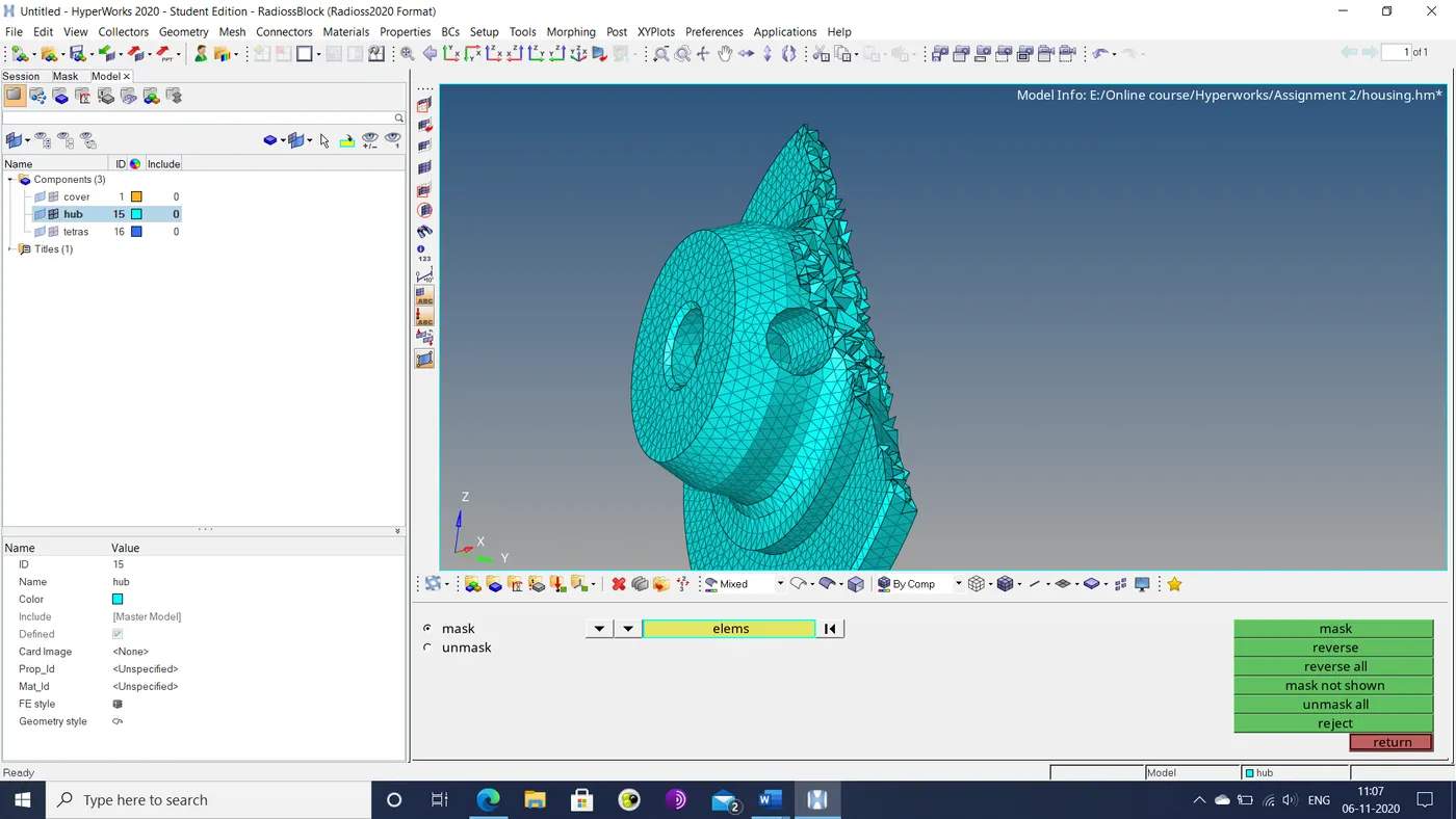
Figure 3: Partial view of hub volume mesh
- The tet-collapse for the 3D mesh is checked via the tool>check elements>3D option.
- For the cover section, the mesh is generated by the 3D>tetra-mesh>volume tetra option. After setting the necessary quality criteria, the following mesh is generated for both the surface and the interior volume of the cover section.
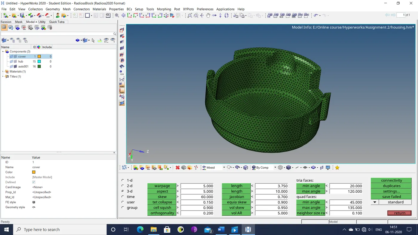
Figure 4: Volume mesh of cover
- The arm bracket component has a relatively simple geometry to allow hexa-meshing.
- The meshing process is started from the base, where a surface mesh is generated on one of its faces via the 2D>auto-mesh option with 10 mm target length (quad only), as shown below.
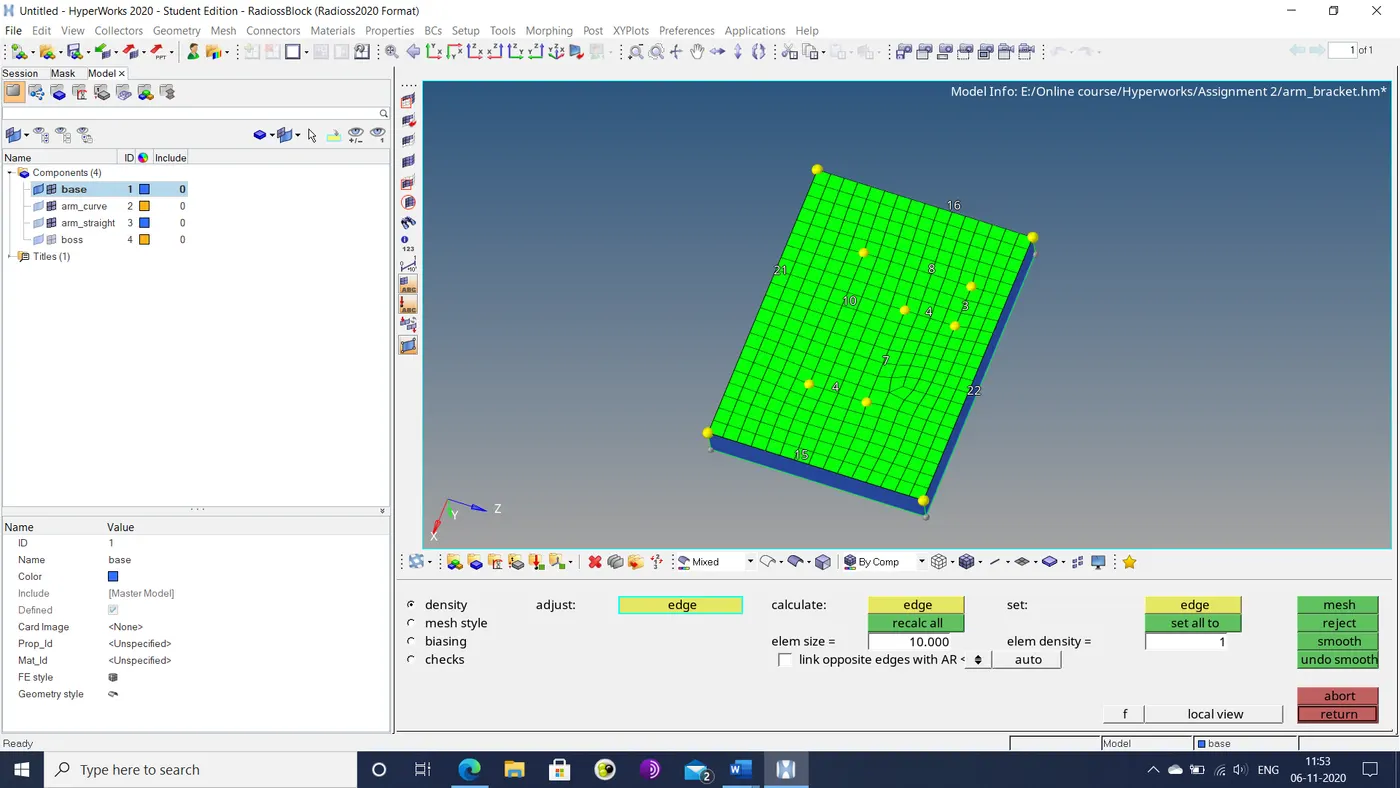
Figure 5: Top surface mesh of arm base
- The base is then meshed with hexa-elements by the 3D>element offset option. The mesh offset direction is determined by the intersection of two perpendicular faces. The resultant hexa-mesh is shown below.
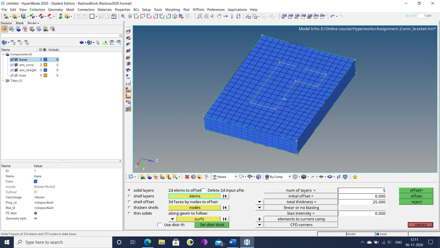
Figure 6: Hexa-mesh of arm base
- The curved section of the arm is then meshed by the 3D>spin option. The spin axis is determined by the curvature of the geometry. The resultant geometry is shown below.
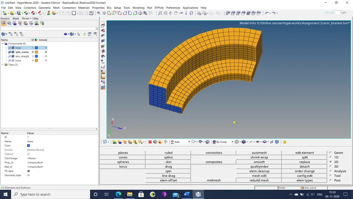
Figure 7: Swept mesh of curved arm section
- A 2D surface mesh is derived from the 3D mesh of the curved arm section by the tool>faces option.
- A destination mesh is made is made for the straight section at the boss end by the auto-mesh option.
- A hexa-mesh is generated between these two surface meshes using the 3D>linear solid option. The resultant mesh is shown below.
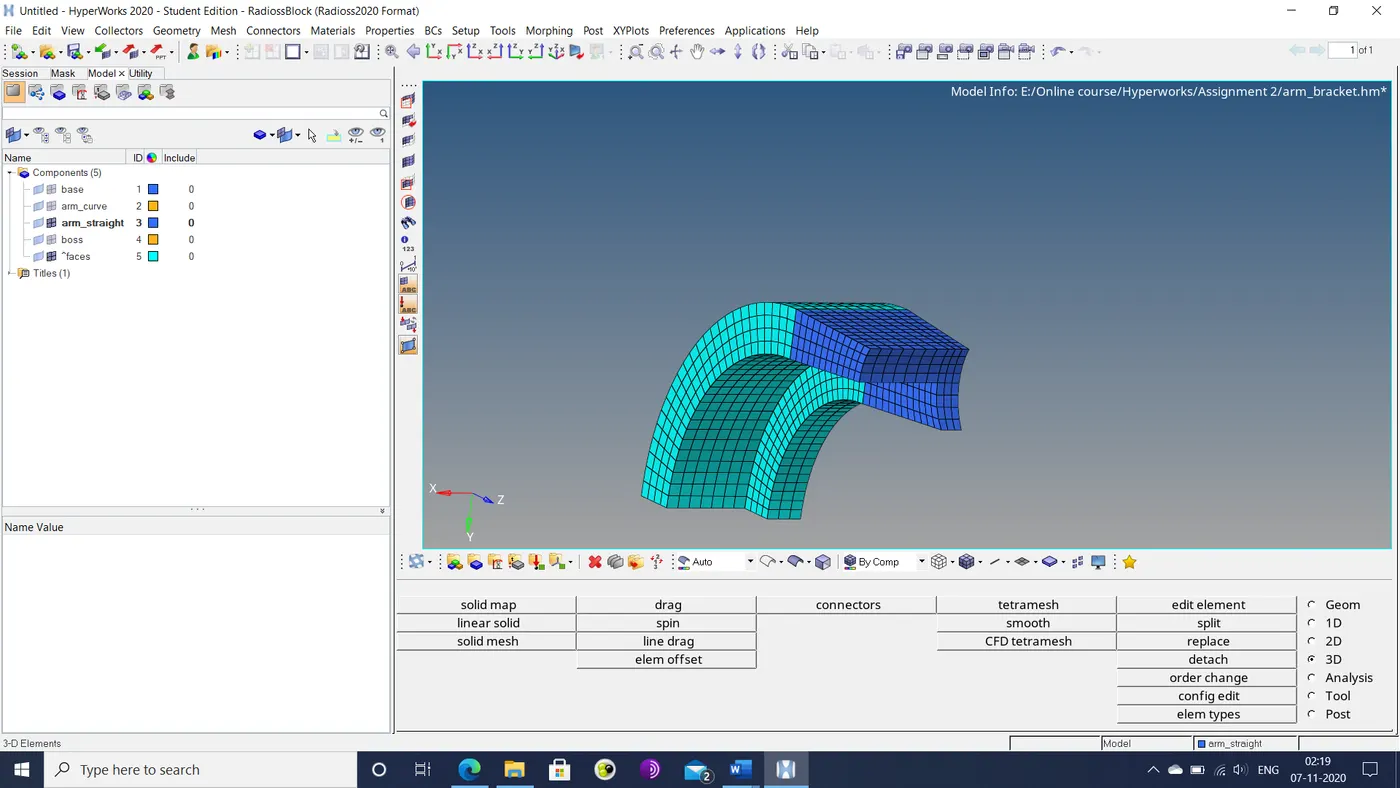
Figure 8: Volume mesh of straight arm section
- For the boss section, a surface mesh is generated at the top surface.
- A point is projected from the base of the straight arm section to the bottom surface of the boss by the tool>project option.
- The 3D mesh is generated using the 3D>solid map>line drag option. Here the mesh direction is determined by the node path generated by the straight arm mesh and 2 points on the boss. The resultant mesh is shown below.
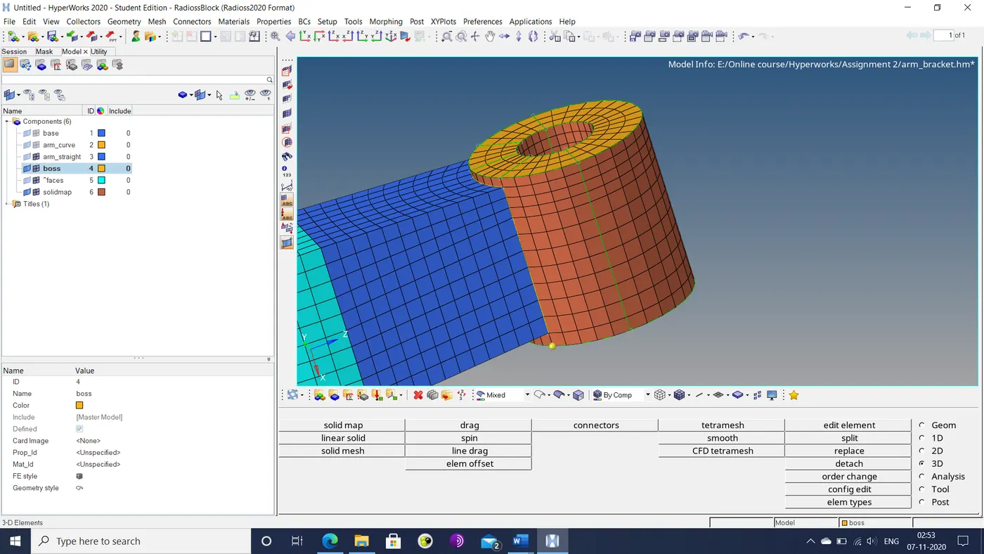
Figure 9: Volume mesh of boss section
- The boss mesh is then moved to the boss geometry by the tool>organize option.
- The final mesh, as illustrated below, is saved.
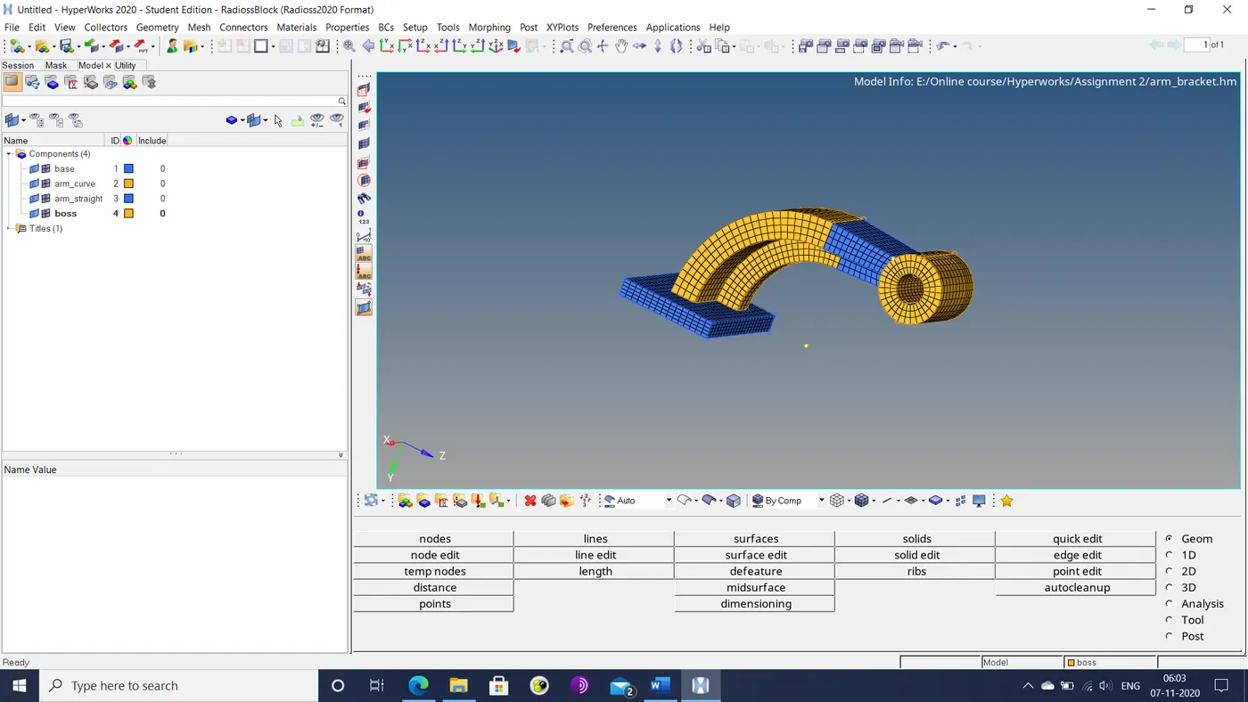
Figure 10: Final mesh of arm bracket
Results: The given components were suitably meshed with tetra and hexa elements. The given engine file was also suitably edited.
- Calculating speed of sound and critical time step was a simple operation that required only the material data in the starter file.
- Editing the engine file was also similarly straightforward. The numbers that needed editing were grouped in suitably labelled lines.
- Tetra-mesh generation was a very fast operation. However, tet-collapse could not be properly fixed.
- Hexa-mesh generation was a far more involved process, since there is no algorithm that can automatically mesh any geometry automatically. Even the relatively simple geometry of the arm bracket took a considerable amount of time to mesh.
Conclusion: Volumetric meshing and engine file editing were suitably practiced in this assignment.