Week 12:Project-1-Meshing of Door Inner Panel Challenge
Skill-lync project 1
Aim: The objective of this project is to generate a representative mid-surface for the component provided and create a 2D shell mesh for the same that meets the specified element quality criteria.
Case setup: The component provided is a 3D CAD model of the interior plastic trim of a car’s front left door, as illustrated below.
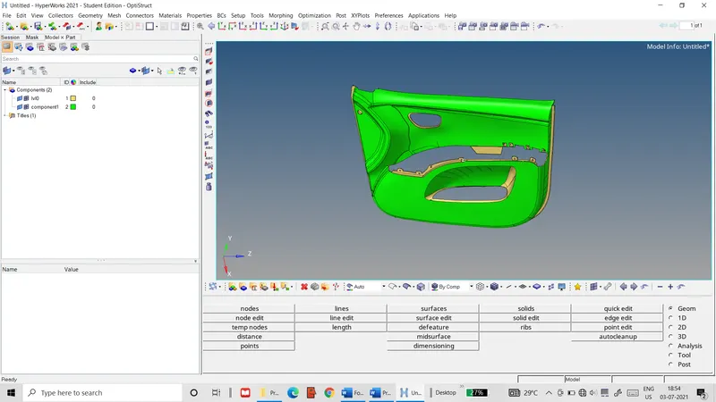 Figure 1: Plastic trim for front left door
A representative mid-surface is to be generated for the entire geometry, including every intricate feature. This mid-surface is to also be meshed with 2D shell elements that have an ideal length of 4 units and meet the following element quality criteria.
Table 1: Element quality criteria
|
S.No. |
Quality Criteria |
Value |
|
1 |
Aspect Ratio |
5 |
|
2 |
Skewness |
45 |
|
3 |
Warping |
15 |
|
4 |
Taper |
0.5 |
|
5 |
Min. Length |
2 Units |
|
6 |
Max. Length |
6 Units |
|
7 |
Min angle Quad |
45 |
|
8 |
Max angle Quad |
135 |
|
9 |
Min angle Tria |
20 |
|
10 |
Max angle Tria |
120 |
|
10 |
Tria % |
10 |
Procedure: The component is worked on with the following sequence of steps: -
- The geometry is imported into the Hyper-works workspace and checked for geometric errors. Any errors found are then rectified using suitable surface or edge editing tools. Missing surfaces are recreated using the Geom>surfaces>ruled tab, as shown below.
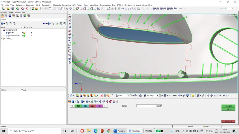 Figure 2: Missing surfaces in component
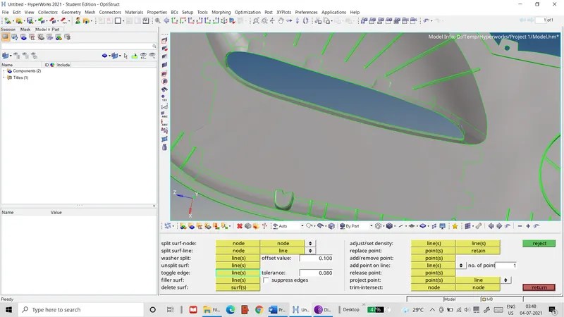 Figure 3: Recreated surfaces
- All the surfaces of the component are moved to one component card using he Tool>organize tab.
- An extended section in this component is deleted and the remaining geometry is repaired, as shown below.
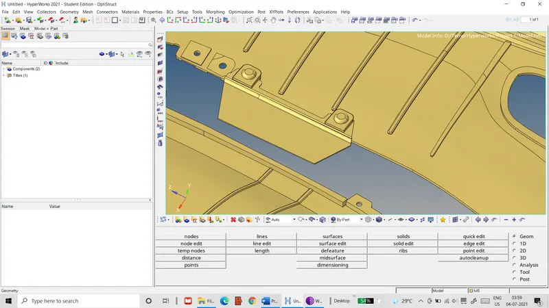 Figure 4: Extended section of component
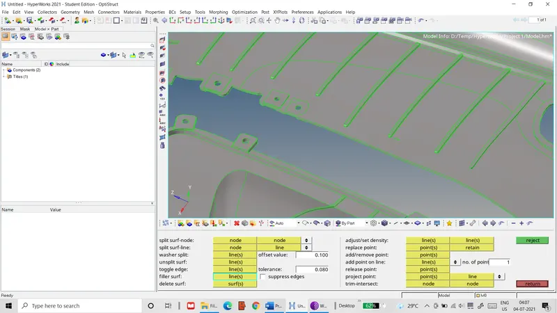 Figure 5: Component after deletion of section and repairing leftover geometry
- Due to the complex geometry and the presence of solid regions of considerable thicknesses, the mid-surface for the main surface of the component is manually generated by offsetting the passenger side surface inwards by half the component thickness, which varies at many locations. These mid-surfaces are assigned to a separate component card.
- The ribs are defeatured and their mid-surfaces are created by offsetting one side by half the rib thickness, which are then extended to the main mid-surface, as shown below. For ribs whose thicknesses are not uniform or difficult to measure, a midline is created on the top surface using the Geom>lines>Midline tab, whick is used to trim the main mis-surface below and use these two lines to generate a rib mid-surface.
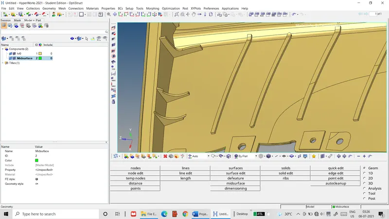 Figure 6: Rib after defeaturing
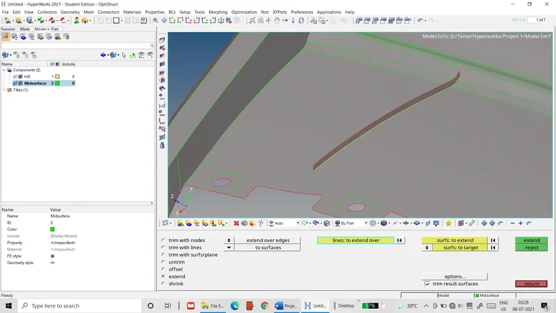 Figure 7: Mid-surface generated from rib
- The protrusions at the hole regions at the region shown below are not modelled since the difference in thickness is not worth considering.
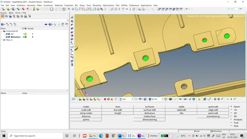 Figure 8: Protrusion at hole region
- The mid-surface for the bevel around the door latch region is modelled as a parallel surface that is connected to the main mid-surface by a mid-line from the surface, as shown below.
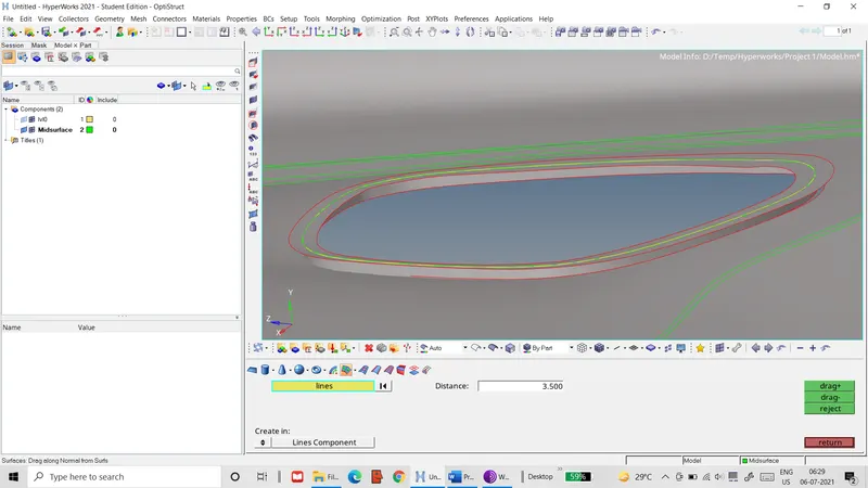 Figure 9: Mid-surface of bevel section at latch region
- The locator pegs are modelled as two crossed mid-surfaces, as shown below.
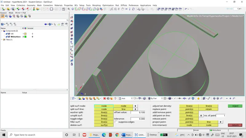 Figure 10: Locator peg with edges defined for mid-surface
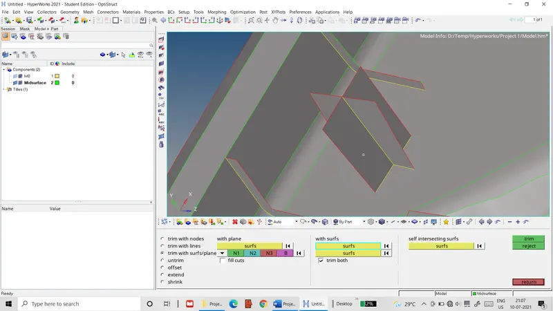 Figure 11: Mid-surface for locator peg
- The locking tabs used to lock the trim into the door frame are modelled as a single mid-surface along its uniform cross-section, as shown below.
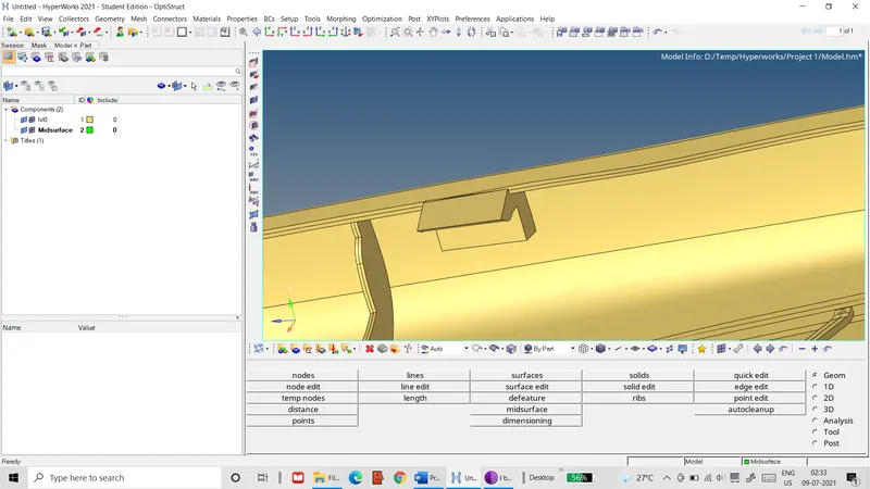 Figure 12: Locking tab
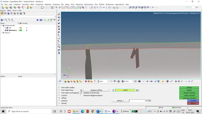 Figure 13: Mid-surface of locking tab
- All unnecessary edges are toggled off and other defeaturing operations are done to ensure the mesh quality for the mid-surface.
- Individual component & property cards are defined for each of the regions with distinct thicknesses and these thicknesses are assigned to their respective property cards.
- Ribs with non-uniform thicknesses are assigned a property card with its average thickness, which is measured either manually or using the Geom>midsurface>review thickness tab. In order to minimize the number of property & component cards, each of these are assigned to regions with thicknesses within a range of 0.1 units from specified thickness.
- The element quality criteria for the 2D mesh are input into the criteria file settings.
- The 2D>automesh tab is used to mesh the mid-surface zone-by-zone. Wherever possible, elements failing the quality criteria are fixed using the 2D>qualityindex tab. This tab is also used to eliminate triangular elements from the mesh. If the qualityindex tool is insufficient for problematic elements, they are manually fixed by smoothing tool and node editing tools.
- After a final check of element quality for the finished mesh, the Tool>edges tab is used to check the connectivity between elements. If any free edges are detected inside the mesh, the equivalence tool is used to connect the elements. Free edges remaining after this operation are manually removed by pasting nodes together by the 2D>replace tab.
- The final mesh is checked for any remaining errors and saved.
Result: The final mesh for the entire mid-surface is illustrated below.
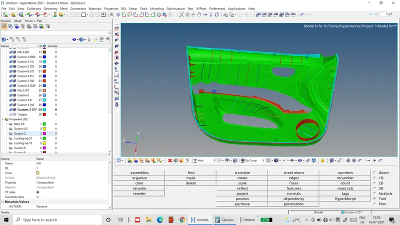 Figure 14: Final FE mesh of door trim
In the regions shown below, the geometry was too restrictive to effectively defeature the geometry for optimal element quality. As a result, a few elements fail the quality criteria in these regions.
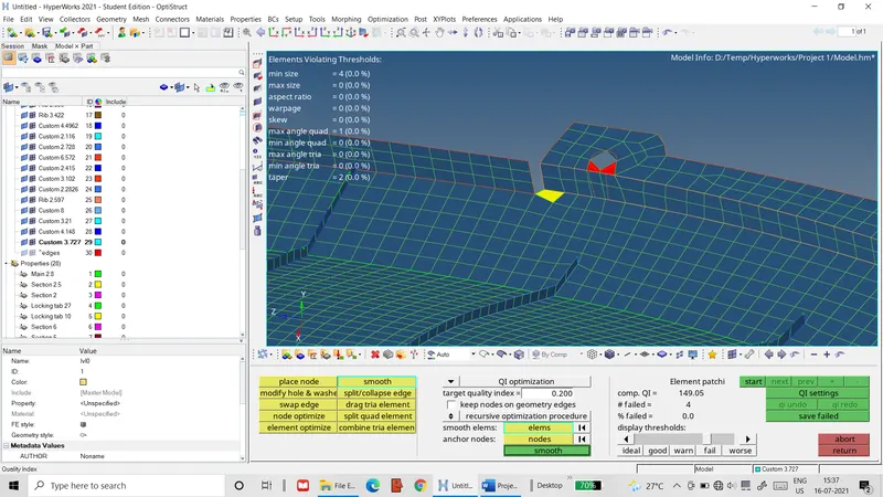 Figure 15: Elements failing quality criteria at hole region
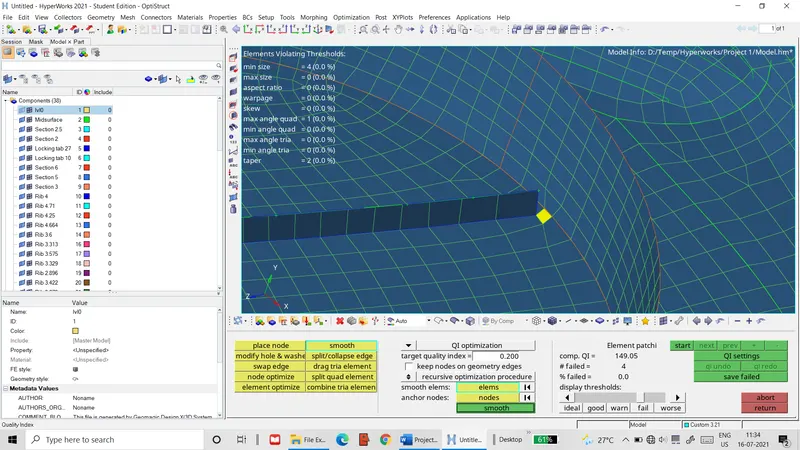 Figure 16: Element failing quality criteria at speaker region