Week 9-Creation of 1D Connectors Challenge
Skill-lync assignment (week 9)
Aim: The objective of this assignment is to generate an FE mesh for the given component as per the specified quality criteria and to connect the various parts of the meshed components together with the specified types of connector elements.
Case setup: The given component is the mid-surface geometry of a frame assembly consisting of 9 separate parts, as illustrated below.
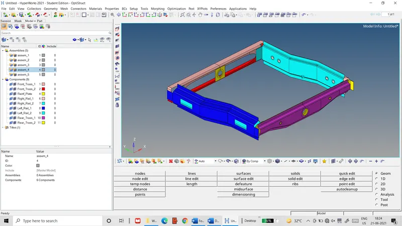 Figure 1: Frame assembly
It is to be meshed with 2D shell elements that meet the following quality criteria.
Table 1: Mesh quality criteria
|
S.No. |
Quality Criteria |
Value |
|
1 |
Aspect Ratio |
5 |
|
2 |
Skewness |
45 |
|
3 |
Warping |
15 |
|
4 |
Taper |
0.5 |
|
5 |
Target Length |
5 Units |
|
6 |
Min. Length |
2 Units |
|
7 |
Max. Length |
8 Units |
|
8 |
Min angle Quad |
45 |
|
9 |
Max angle Quad |
135 |
|
10 |
Min angle Tria |
30 |
|
11 |
Max angle Tria |
110 |
|
12 |
Tria % |
15 |
The various parts of this assembly are to be connected by the following connector element types between the respective parts: -
- Right_Rail_2 & Front_Truss_1: Seam-Quad (angled + capped + L)
- Left_Rail_2 & Front_Truss_1: Quad elements
- Front_Truss_2, Front_Truss_1 & Right_Rail_1: Spot welds 2 layers thick with diameter of 5 mm.
- Front_Truss_2, Front_Truss_1 & Left_Rail_1: Hexa (adhesive)
- Rear_Truss_2 & Right_Rail_2: Bolt connector
- Rear_Truss_2 & Left_Rail_2: Bolt connector
- Right_Rail_1 & Right_Rail_2: Spot welds with rigid elements
- Left_Rail_1 & Left_Rail_2: Spot welds with spring elements
- Remaining parts: Suitable connectors
Procedure: The mesh and the connector elements are generated through the following sequence of steps: -
- The component model is imported into the Hyperworks workspace.
- The quality criteria are set for the component in the criteria file settings.
- The various parts are meshed individually using the automesh tool. The resultant meshes are cleaned and optimised with the aid of the qualityindex tool.
- A material card for steel and a property card are then created.
- The 2D>connectors>seam tab is used to generate the seam weld between the parts Right_Rail_2 and Front_Truss_1 with the specified element type, as shown below.
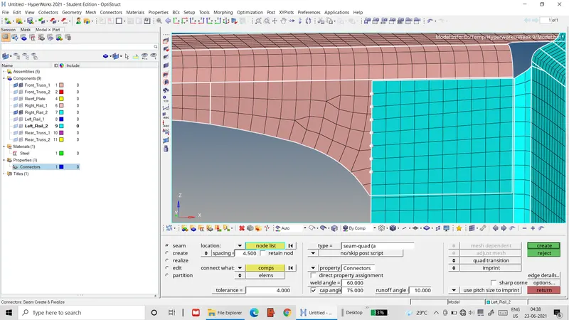 Figure 2: Seam weld definition between Right_Rail_2 & Front_Truss_1
- The altered meshes of the connected parts are cleaned and optimized to meet the element quality criteria.
- The same method is used to define connectors with quad elements between the parts Left_Rail_2 and Front_Truss_1, as shown below, which is followed by mesh cleaning.
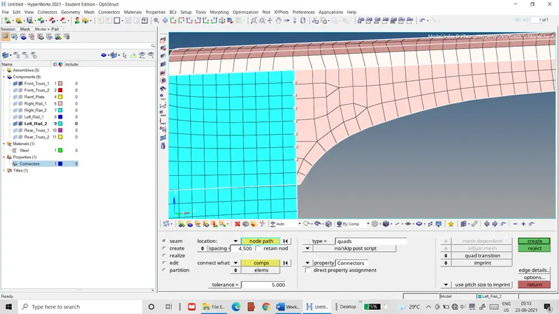 Figure 3: Seam weld definition between Left_Rail_2 & Front_Truss_1
- The 2D>connectors>spot tab is used to define a spot weld 5 mm in diameter and 2 layers thick between the parts Front_Truss_2 & Front_Truss_1 and Front_Truss_1 & Right_Rail_1, as shown below.
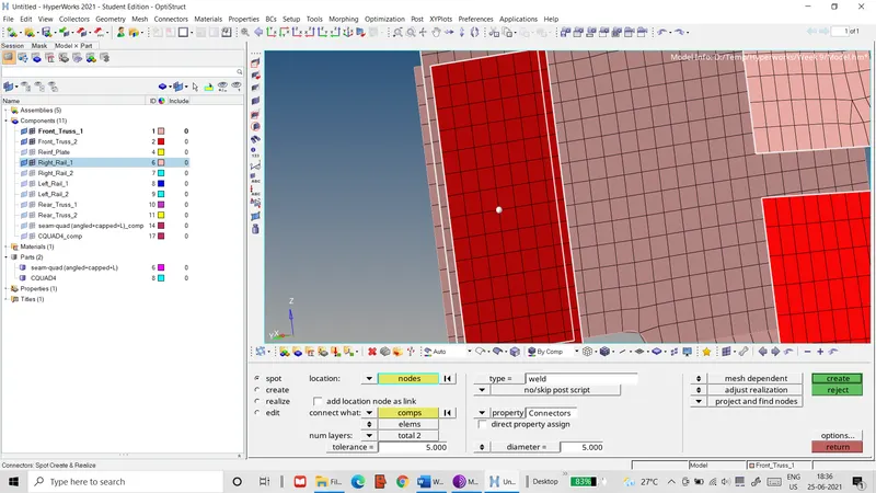 Figure 4: Spot weld definition between Front_Truss_1 & Front_Truss _2
- The 2D>connectors>seam tab is used to define a single coat of adhesive between the parts Front_Truss_2 & Front_Truss_1 and Front_Truss_1 & Left_Rail_1 using hexa (adhesive) elements, as shown below.
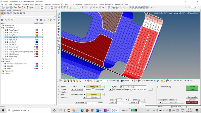 Figure 5: Adhesive seam definition between Front_Truss_1 & Front_Truss_2
- The 2D>connectors>bolt tab is used to define 2 bolt connections between the parts Right_Rail_2 & Rear_Truss_2, as shown below.
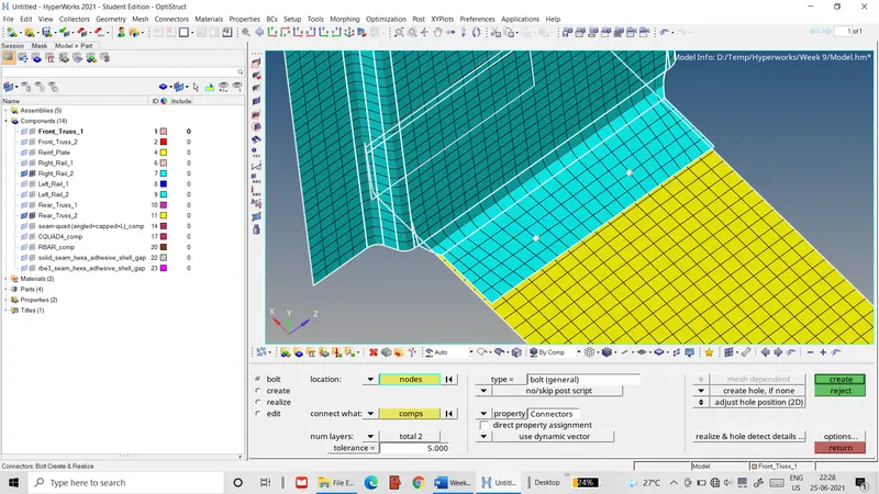 Figure 6: Bolt definition between Right_Rail_2 & Rear_Truss_2
The settings are adjusted so that bolt holes are created in both parts with a 6 mm diameter, 8 nodes around the hole and a washer region around it 3 mm wide.
- The altered meshes of the connected parts are then rebuilt to meet element quality criteria.
- In a similar manner, 2 bolt connections are defined between the parts Rear_Truss_2 and Left_Rail_2.
- The 2D>connectors>spot tab is used to define 6 spot welds between the parts Right_Rail_1 & Right_Rail_2 with rigid elements, as illustrated below.
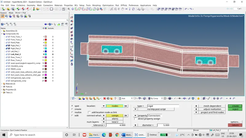 Figure 7: Spot weld definition with rigid elements between Right_Rail_1 & Right_Rail_2
- The same method is used to define 6 spot welds between the parts Left_Rail_1 & Left_Rail_2 with spring elements.
- The Rear_Truss_1 & Rear_truss_2 parts are connected with 2 adhesive strips using the 2D>connectors>seam tab. The adhesive strips are chosen since their generation does not disturb the existing part meshes and they can be easily created over the length of these relatively large parts.
- The Rear_Truss_2 part is connected with the Right_Rail_1 & Left_Rail_1 parts with 5 mm spot welds with spring elements. Like with the rear trusses, spot welds are chosen so that they can be added without disturbing the part meshes.
- Finally, the Reinf_Plate part is connected with the Front_Truss_1 and Front_Truss_2 parts with 4 5mm spot welds with rigid elements.
Result: The final mesh of the complete assembly and the connectors between the parts are compiled below.
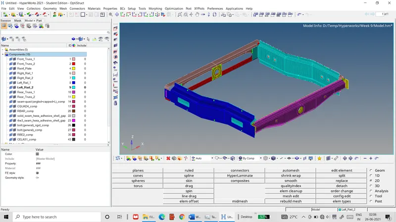 Figure 8: Final FE mesh of entire assembly
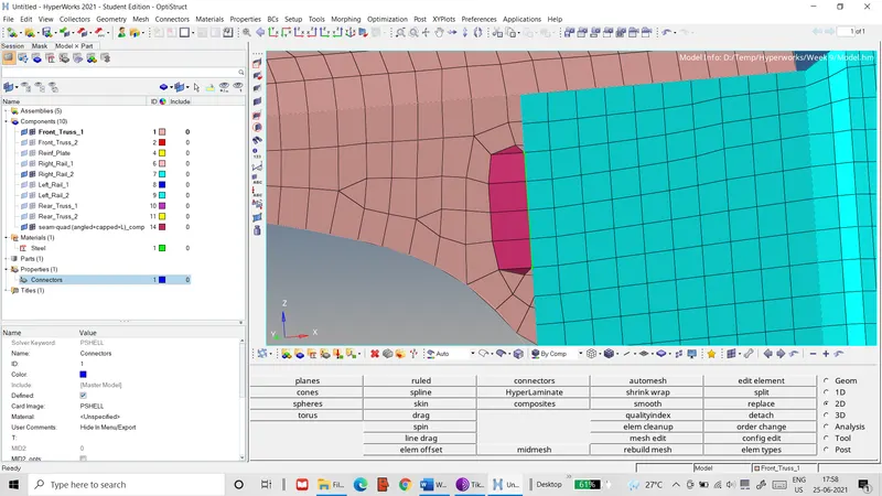 Figure 9: Seam weld mesh with seam-quad elements
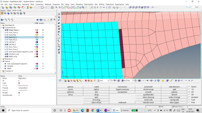 Figure 10: Seam weld mesh with quad elements
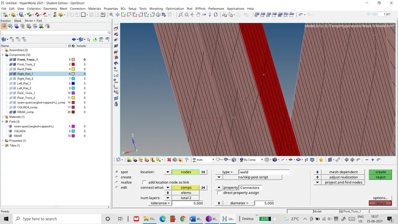 Figure 11: Spot weld mesh with weld element
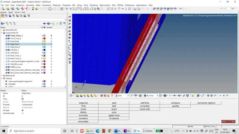 Figure 12: Adhesive strip mesh with hexa (adhesive) elements
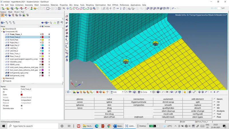 Figure 13: Bolt elements between Rear_Truss_2 & Right_Rail_2
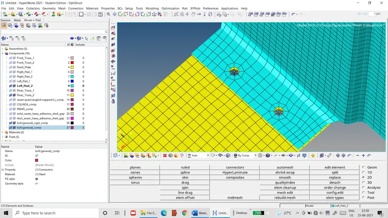 Figure 14: Bolt mesh between Rear_Truss_2 & Left_Rail_2
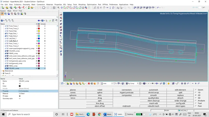 Figure 15: Spot weld mesh with rigid elements
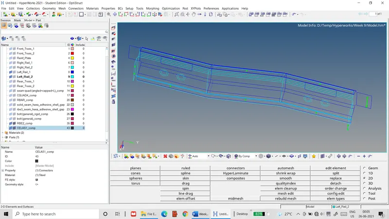 Figure 16: Spot weld with spring element
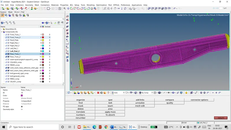 Figure 17: Adhesive mesh between Rear_Truss_1 & Rear_Truss_2
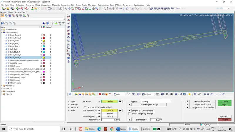 Figure 18: Spot welds with spring element between Rear_Truss_2 & Right_Rail_1 and Rear_Truss_2 & Left_Rail_1
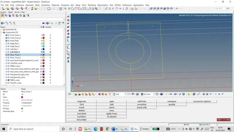 Figure 19: Spot welds with rigid elements between Reinf_Plate & Front_Truss_1 and Reinf_Plate & Front_Truss_2